JP2006351237A - Switching device - Google Patents
Switching device Download PDFInfo
- Publication number
- JP2006351237A JP2006351237A JP2005172556A JP2005172556A JP2006351237A JP 2006351237 A JP2006351237 A JP 2006351237A JP 2005172556 A JP2005172556 A JP 2005172556A JP 2005172556 A JP2005172556 A JP 2005172556A JP 2006351237 A JP2006351237 A JP 2006351237A
- Authority
- JP
- Japan
- Prior art keywords
- actuator
- side wall
- housing
- switch
- operating member
- Prior art date
- Legal status (The legal status is an assumption and is not a legal conclusion. Google has not performed a legal analysis and makes no representation as to the accuracy of the status listed.)
- Withdrawn
Links
- 238000005452 bending Methods 0.000 claims description 7
- 238000004519 manufacturing process Methods 0.000 abstract description 3
- 230000000630 rising effect Effects 0.000 description 10
- 239000002184 metal Substances 0.000 description 2
- 229910000906 Bronze Inorganic materials 0.000 description 1
- OAICVXFJPJFONN-UHFFFAOYSA-N Phosphorus Chemical compound [P] OAICVXFJPJFONN-UHFFFAOYSA-N 0.000 description 1
- 238000013459 approach Methods 0.000 description 1
- 239000010974 bronze Substances 0.000 description 1
- 238000004587 chromatography analysis Methods 0.000 description 1
- KUNSUQLRTQLHQQ-UHFFFAOYSA-N copper tin Chemical compound [Cu].[Sn] KUNSUQLRTQLHQQ-UHFFFAOYSA-N 0.000 description 1
- 239000011810 insulating material Substances 0.000 description 1
- 239000000463 material Substances 0.000 description 1
- 239000011347 resin Substances 0.000 description 1
- 229920005989 resin Polymers 0.000 description 1
- 229910001220 stainless steel Inorganic materials 0.000 description 1
- 239000010935 stainless steel Substances 0.000 description 1
Images


Classifications
-
- H—ELECTRICITY
- H01—ELECTRIC ELEMENTS
- H01H—ELECTRIC SWITCHES; RELAYS; SELECTORS; EMERGENCY PROTECTIVE DEVICES
- H01H13/00—Switches having rectilinearly-movable operating part or parts adapted for pushing or pulling in one direction only, e.g. push-button switch
- H01H13/02—Details
- H01H13/12—Movable parts; Contacts mounted thereon
- H01H13/14—Operating parts, e.g. push-button
- H01H13/18—Operating parts, e.g. push-button adapted for actuation at a limit or other predetermined position in the path of a body, the relative movement of switch and body being primarily for a purpose other than the actuation of the switch, e.g. door switch, limit switch, floor-levelling switch of a lift
- H01H13/186—Operating parts, e.g. push-button adapted for actuation at a limit or other predetermined position in the path of a body, the relative movement of switch and body being primarily for a purpose other than the actuation of the switch, e.g. door switch, limit switch, floor-levelling switch of a lift wherein the pushbutton is rectilinearly actuated by a lever pivoting on the housing of the switch
-
- H—ELECTRICITY
- H01—ELECTRIC ELEMENTS
- H01H—ELECTRIC SWITCHES; RELAYS; SELECTORS; EMERGENCY PROTECTIVE DEVICES
- H01H21/00—Switches operated by an operating part in the form of a pivotable member acted upon directly by a solid body, e.g. by a hand
- H01H21/02—Details
- H01H21/18—Movable parts; Contacts mounted thereon
- H01H21/22—Operating parts, e.g. handle
- H01H21/24—Operating parts, e.g. handle biased to return to normal position upon removal of operating force
-
- H—ELECTRICITY
- H01—ELECTRIC ELEMENTS
- H01H—ELECTRIC SWITCHES; RELAYS; SELECTORS; EMERGENCY PROTECTIVE DEVICES
- H01H21/00—Switches operated by an operating part in the form of a pivotable member acted upon directly by a solid body, e.g. by a hand
- H01H21/02—Details
- H01H21/18—Movable parts; Contacts mounted thereon
- H01H21/22—Operating parts, e.g. handle
- H01H21/24—Operating parts, e.g. handle biased to return to normal position upon removal of operating force
- H01H21/28—Operating parts, e.g. handle biased to return to normal position upon removal of operating force adapted for actuation at a limit or other predetermined position in the path of a body, the relative movement of switch and body being primarily for a purpose other than the actuation of the switch, e.g. door switch, limit switch, floor-levelling switch of a lift
- H01H21/282—Operating parts, e.g. handle biased to return to normal position upon removal of operating force adapted for actuation at a limit or other predetermined position in the path of a body, the relative movement of switch and body being primarily for a purpose other than the actuation of the switch, e.g. door switch, limit switch, floor-levelling switch of a lift for actuation by moving a closing member, e.g. door, cover
Landscapes
- Push-Button Switches (AREA)
- Mechanisms For Operating Contacts (AREA)
- Rotary Switch, Piano Key Switch, And Lever Switch (AREA)
Abstract
Description
本発明は、スイッチ装置に係わり、外部の作動部材を一方向に移動操作することによりアクチュエータが作動部材の移動方向と直交する方向に回動してスイッチ回路が切り換わるスイッチ装置に関する。 The present invention relates to a switch device, and more particularly to a switch device in which an actuator is rotated in a direction orthogonal to the moving direction of an operating member by moving an external operating member in one direction to switch a switch circuit.
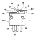
従来のスイッチ装置を特許文献1に基づいて図6、図7で説明すると、従来のスイッチ装置20は、筐体21が配設され、この筐体21の内部に所定のスイッチ回路(図示せず)が形成されている。前記筐体21には、内部のスイッチ回路に接続する複数の端子部22が、図示下方側に延出形成されている。
また、アクチュエータ23は、金属板からなり、図示左側の取付脚部24が筐体21に圧入等で固着されて筐体21と一体化されている。
The conventional switch device will be described with reference to FIG. 6 and FIG. 7 based on
The
前記アクチュエータ23は、取付脚部24が略直角に図示水平状に屈曲されて支持部25が形成され、この支持部25の先部には、取付脚部24の曲げ方向と反対方向に角度A(略35度)で屈曲形成して立上がり部26が形成されている。
また、立上がり部26の先側には、支持部25と略平行な接触部形成部27が形成されている。
前記接触部形成部27の表面側には、傾斜状の立上がり部26の延長線上に作動体接触部28が突出形成されている。
In the
Further, a contact
On the surface side of the contact
また、接触部形成部27の下面には、筐体21から所定高さで上方に突出するスイッチ操作部30が形成され、このスイッチ操作部30が接触部形成部27に押圧されると、下方に降下して、筐体21内部のスイッチ回路(図示せず)が切り換わるようになっている。
また、スイッチ装置20の外部には、略水平状のアクチュエータ23の支持部25上に、矢印B方向に移動操作可能な作動部材31が配設されている。
Further, on the lower surface of the contact
In addition, an
このような従来のスイッチ装置20は、図6に示す初期状態において、スイッチ操作部30が所定高さに上昇して、アクチュータ23の支持部25と接触部形成部27とが略水平状になっている。
このような初期状態において、作動部材31を図示右方向の矢印B方向に移動操作すると、アクチュエータ23の略35度で傾斜する立上がり部26が押圧されて下方に降下する。この時の立上がり部26の降下量は、作動部材31の矢印B方向の移動量より小さい。
In such a
In such an initial state, when the actuating
そして、立上がり部26が降下することで、略水平状の支持部25が下方側に弾性変形して、図7に示すように、接触部形成部27が矢印C方向に回動する。
このことにより、スイッチ操作部30が接触部形成部27により筐体21内部に押し込まれて、筐体21内部のスイッチ回路がOFFからONに切り換わるようになっている。
また、スイッチ操作部30を押し込んだ状態から、作動部材31を矢印Bと逆方向に移動させると、スイッチ操作部30の押し込みが解除され、アクチュエータ23が自身の弾性力で図6に示す初期状態に復帰する。
このことにより、内部のスイッチ回路がOFFするようになっている。
As a result, the
Further, when the
As a result, the internal switch circuit is turned off.
しかし、従来のスイッチ装置20のアクチュエータ23は、立上げ部26の角度Aが略35度に形成しているので、作動部材31の矢印B方向の移動量より立上がり部26の回動量が小さい。
そのために、スイッチ操作部30を筐体21内部に押し込むスイッチング操作時の作動部材31の矢印B方向への移動量が大きくなる問題があった。
このような作動部材31の移動量が大きいと、スイッチ操作部30の押し込み速度が遅くなり、スイッチング操作時の応答速度が遅くなるおそれがあった。
However, in the
Therefore, there has been a problem that the amount of movement of the
When the movement amount of the
また、アクチュータ23は、取付脚部24と、この取付脚部24を略直角の水平状に屈曲した支持部25と、この支持部25の先部を上方に角度A(例えば35度)屈曲形成した立上がり部26と、この立上がり部26の先側に形成した接触部形成部27と、この接触部形成部27の表面側に突出形成した作動体接触部28とで構成されている。そのために、アクチュエータ23の加工が複雑となる問題があった。
本発明は、前述したような課題を解決し、移動量の小さな作動部材でスイッチング操作時の応答速度を向上できると共に、構造が簡単で製造が容易なアクチュエータを用いたスイッチ装置を提供することを目的とする。
The
The present invention solves the above-described problems, and provides a switch device using an actuator that can improve the response speed during a switching operation with an operation member having a small amount of movement, and that has a simple structure and is easy to manufacture. Objective.
前記課題を解決するための第1の手段として本発明のスイッチ装置は、内部にスイッチ回路が形成された筐体と、一端部側に支持部が形成されて他端部側が自由端状に形成されたアクチュエータと、前記筐体の一方の側壁から外部に所定高さで突出して前記アクチュエータの回動により前記筐体内部に押し込まれて前記スイッチ回路を切り換え可能なスイッチ操作部とを備え、
前記アクチュエータには、外部の作動部材が押圧操作可能な押圧部が形成され、前記支持部を前記筐体に回動可能に支持した状態で、前記作動部材を前記一方の側壁と平行な一方向に移動させると、前記押圧部が前記一方の側壁に近づく方向に押圧されて前記アクチュエータが前記支持部を支点として回動可能になっており、前記作動部材を一方向に移動させて前記アクチュエータを回動させた時の前記押圧部の回動量が、前記作動部材の前記一方向への移動量よりも大きくなるようにしたことを特徴とする。
また、前記課題を解決するための第2の手段として、前記アクチュエータは、弾性を有する板状部材からなり、前記押圧部は、前記一端部側と前記他端部側との間に、前記筐体の一方の側壁から離れる方向に逆V字状に突出形成した凸部からなることを特徴とする請求項1記載のスイッチ装置。
As a first means for solving the above problems, the switch device of the present invention includes a housing in which a switch circuit is formed, a support portion formed on one end side, and a free end on the other end side. And a switch operation unit that protrudes to the outside from one side wall of the casing at a predetermined height and is pushed into the casing by the rotation of the actuator to switch the switch circuit,
The actuator has a pressing portion that can be operated by an external operating member, and the operating member is supported in one direction parallel to the one side wall while the support portion is rotatably supported by the housing. When the actuator is moved to the position, the pressing portion is pressed in a direction approaching the one side wall so that the actuator can be rotated with the support portion as a fulcrum, and the operating member is moved in one direction to move the actuator. The amount of rotation of the pressing portion when rotated is set to be larger than the amount of movement of the operating member in the one direction.
As a second means for solving the above-mentioned problem, the actuator is made of an elastic plate member, and the pressing portion is disposed between the one end portion side and the other end portion side. 2. The switch device according to
また、前記課題を解決するための第3の手段として、前記凸部は、前記一端部側に対する突出角度(α)が45度以上に形成されていることを特徴とする。
また、前記課題を解決するための第4の手段として本発明の第2の実施の形態のスイッチ装置は、内部にスイッチ回路が形成された筐体と、一端部側に支持部が形成されて他端部側が自由端状に形成されたアクチュエータと、前記筐体の一方の側壁から外部に所定高さで突出して前記アクチュエータの回動により前記筐体内部に押し込まれて前記スイッチ回路を切り換え可能なスイッチ操作部とを備え、前記アクチュエータには、外部の作動部材が押圧操作可能な押圧部が形成され、前記支持部を前記筐体に回動可能に支持した状態で、前記作動部材を前記一方の側壁と平行な一方向に移動させると、前記押圧部が前記一方の側壁に近づく方向に押圧されて前記アクチュエータが前記支持部を支点として回動可能になっており、前記アクチュエータの前記他端部側には、前記他端部側を前記一方の側壁から離れる方向に弾性付勢する付勢部材が配設され、
前記操作部材を、前記一方向に移動させて前記押圧部を押圧した状態から前記一方向と反対方向の他方向に戻すと、前記弾性部材の付勢力で前記アクチュエータが前記一方の側壁から離れる方向に回動することを特徴とする。
また、前記課題を解決するための第5の手段として、前記アクチュエータは、弾性を有する板状部材からなり、前記付勢部材は、前記他端部側の一部を前記筐体の前記一方の側壁側に片持ち状に切り曲げ形成したことを特徴とする。
Further, as a third means for solving the above-mentioned problem, the convex portion is characterized in that a protruding angle (α) with respect to the one end side is formed to be 45 degrees or more.
Further, as a fourth means for solving the above problem, the switch device according to the second embodiment of the present invention includes a housing in which a switch circuit is formed and a support portion formed on one end side. The switch circuit can be switched by an actuator having a free end on the other end side and a predetermined height projecting from one side wall of the casing and being pushed into the casing by the rotation of the actuator. The actuator is provided with a pressing portion that can be operated by an external operating member, and the support member is rotatably supported by the housing. When the actuator is moved in one direction parallel to the one side wall, the pressing portion is pressed in a direction approaching the one side wall, so that the actuator can rotate about the support portion. The said other end of the chromatography data, biasing member elastically biasing the other end side in the direction away from the side wall of the one is disposed,
When the operating member is moved in the one direction and returned to the other direction opposite to the one direction from the state where the pressing portion is pressed, the actuator is separated from the one side wall by the biasing force of the elastic member. Rotating to
As a fifth means for solving the above-mentioned problem, the actuator is made of a plate-like member having elasticity, and the biasing member has a part on the other end side of the one side of the casing. It is characterized in that it is cut and formed in a cantilever shape on the side wall side.
また、前記課題を解決するための第6の手段として、前記筐体の一方の側壁には、前記付勢部材の自由端部が当接可能な当接部材が配設され、前記作動部材によって前記押圧部が前記一方の側壁に近づく方向に押圧されると、前記付勢部材の前記自由端部が前記当接部材によって動きが規制されることを特徴とする。
また、前記課題を解決するための第7の手段として、前記付勢部材の前記自由端部を前記当接部材に当接した状態で、前記作動部材を前記一方向に移動させて前記押圧部を押圧すると、前記付勢部材が反転して前記アクチュエータの前記他端部側に対する付勢力が弱くなり、前記他端部側が前記スイッチ操作部を前記筐体内部に押し込む方向に弾性変形することを特徴とする。
Further, as a sixth means for solving the above-described problem, a contact member capable of contacting the free end of the biasing member is disposed on one side wall of the casing, and the operation member When the pressing portion is pressed in a direction approaching the one side wall, the movement of the free end portion of the biasing member is restricted by the contact member.
Further, as a seventh means for solving the problem, the pressing member is moved in the one direction while the free end portion of the biasing member is in contact with the contact member. When the pressing member is pressed, the biasing member is reversed to weaken the biasing force of the actuator against the other end side, and the other end side is elastically deformed in a direction to push the switch operation unit into the housing. Features.
本発明の第1の実施の形態のスイッチ装置のアクチュエータには、外部の作動部材が押圧操作可能な押圧部が形成され、支持部を筐体に回動可能に支持した状態で、作動部材を一方の側壁と平行な一方向に移動させると、押圧部が一方の側壁に近づく方向に押圧されてアクチュエータが支持部を支点として回動可能になっており、作動部材を一方向に移動させてアクチュエータを回動させた時の押圧部の回動量が、作動部材の一方向への移動量よりも大きくなるようにしたので、作動部材の小さな移動量で押圧部を大きく回動させることができ、スイッチ操作部を迅速に押し下げることができる。
そのために、筐体内部のスイッチ回路切り換えの応答速度を向上できる。
また、アクチュエータは、弾性を有する板状部材からなり、押圧部は、一端部側と他端部側との間に、筐体の一方の側壁から離れる方向に逆V字状に突出形成した凸部からなるので、プレス加工等で凸部を容易に形成することができ、アクチュエータの製造が容易である。
また、凸部は、一端部側に対する突出角度(α)が45度以上に形成されているので、作動部材の移動量より押圧部である凸部の回動量を確実に大きくできる。そのために、スイッチ回路切り換えの応答速度を向上できる。
In the actuator of the switch device according to the first embodiment of the present invention, a pressing portion that can be operated by an external operating member is formed, and the operating member is mounted in a state in which the supporting portion is rotatably supported by the housing. When moving in one direction parallel to one side wall, the pressing part is pressed in a direction approaching one side wall, and the actuator can rotate about the support part, and the operating member is moved in one direction. Since the rotation amount of the pressing portion when the actuator is rotated is made larger than the movement amount of the operating member in one direction, the pressing portion can be rotated largely with a small movement amount of the operating member. The switch operation unit can be pushed down quickly.
Therefore, the response speed of switching the switch circuit inside the housing can be improved.
Further, the actuator is made of a plate member having elasticity, and the pressing portion is a protrusion formed in an inverted V shape in a direction away from one side wall of the housing between the one end side and the other end side. Since it consists of a part, a convex part can be easily formed by press work etc., and manufacture of an actuator is easy.
Moreover, since the protrusion has a protrusion angle (α) of 45 degrees or more with respect to the one end, the amount of rotation of the protrusion, which is the pressing portion, can be reliably increased from the amount of movement of the operating member. Therefore, the response speed of switching the switch circuit can be improved.
また、本発明の第2の実施の形態のアクチュエータには、外部の作動部材が押圧操作可能な押圧部が形成され、支持部を筐体に回動可能に支持した状態で、作動部材を一方の側壁と平行な一方向に移動させると、押圧部が一方の側壁に近づく方向に押圧されてアクチュエータが支持部を支点として回動可能になっており、アクチュエータの他端部側には、他端部側を一方の側壁から離れる方向に弾性付勢する付勢部材が配設され、操作部材を、一方向に移動させて押圧部を押圧した状態から一方向と反対方向の他方向に戻すと、弾性部材の付勢力でアクチュエータが一方の側壁から離れる方向に回動するので、スイッチ押圧部の復帰力が弱くてもアクチュエータを確実に初期状態に戻すことができる。
また、アクチュエータは、弾性を有する板状部材からなり、付勢部材は、他端部側の一部を筐体の一方の側壁側に片持ち状に切り曲げ形成したので、付勢部材をアクチュエータに一体形成でき、組立性が良い。
In addition, the actuator according to the second embodiment of the present invention has a pressing portion that can be operated by an external operating member, and the operating member is supported while the support portion is rotatably supported by the housing. When the actuator is moved in one direction parallel to the side wall of the actuator, the pressing portion is pressed in a direction approaching one of the side walls, so that the actuator can rotate about the support portion. A biasing member that elastically biases the end side in a direction away from one of the side walls is disposed, and the operation member is moved in one direction to return to the other direction opposite to the one direction from the pressed state. Since the actuator is rotated in a direction away from the one side wall by the biasing force of the elastic member, the actuator can be reliably returned to the initial state even if the return force of the switch pressing portion is weak.
The actuator is made of a plate member having elasticity, and the urging member is formed by cutting and bending a part of the other end side to one side wall side of the housing in a cantilevered manner. Can be formed integrally with each other, and is easy to assemble.
また、筐体の一方の側壁には、付勢部材の自由端部が当接可能な当接部材が配設され、作動部材によって押圧部が一方の側壁に近づく方向に押圧されると、付勢部材の自由端部が当接部材によって動きが規制されるので、当接部材に自由端部を当接させることで、付勢部材の付勢力が大きくなり、更に確実にアクチュエータを初期状態に戻すことができる。 In addition, an abutting member capable of abutting the free end of the biasing member is disposed on one side wall of the casing, and when the pressing portion is pressed in a direction approaching the one side wall by the operating member, Since the movement of the free end of the biasing member is restricted by the abutting member, the biasing force of the biasing member is increased by bringing the free end into contact with the abutting member, and the actuator is surely returned to the initial state. Can be returned.
また、付勢部材の自由端部を当接部材に当接した状態で、作動部材を一方向に移動させて押圧部を押圧すると、付勢部材が反転してアクチュエータの他端部側に対する付勢力が弱くなり、他端部側がスイッチ操作部を筐体内部に押し込む方向に弾性変形するので、スイッチ操作部を更に迅速に筐体内部に更に押し込んでスイッチ回路切り換えの応答速度を更に向上できる。 Further, when the operating member is moved in one direction and the pressing portion is pressed while the free end portion of the urging member is in contact with the abutting member, the urging member is reversed and applied to the other end side of the actuator. Since the force is weakened and the other end side is elastically deformed in the direction of pushing the switch operating portion into the housing, the switch operating portion can be pushed further into the housing more quickly to further improve the switching speed of switching the switch circuit.
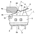
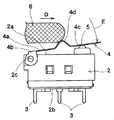
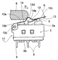
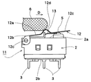
以下、本発明のスイッチ装置の第1、第2の実施の形態を図面に基づいて説明する。図1は本発明の第1の実施の形態のスイッチング操作前の側面図であり、図2は図1のスイッチング操作を説明する側面図であり、図3は本発明の第2の実施の形態のスイッチング操作前の側面図であり、図4、図5は図1のスイッチング操作を説明する側面図である。 Hereinafter, first and second embodiments of a switch device of the present invention will be described with reference to the drawings. FIG. 1 is a side view before the switching operation of the first embodiment of the present invention, FIG. 2 is a side view illustrating the switching operation of FIG. 1, and FIG. 3 is a second embodiment of the present invention. FIG. 4 and FIG. 5 are side views illustrating the switching operation of FIG.
まず、第1の実施の形態のスイッチ装置1は、図1に示すように、内部にスイッチ回路(図示せず)が形成された樹脂材料等の絶縁材料からなる筐体2が配設されている。この筐体2は、図示上部に一方の側壁2aが形成され、図示下部に他方の側壁2bが形成されている。
前記筐体2の他方の側壁2bからは、内部のスイッチ回路に接続された複数の端子部3が延出形成されている。
また、筐体2の一方の側壁2aの図示左側には、後述するアクチュエータ4を回動可能に支持する回動支持部2cが形成されている。
First, as shown in FIG. 1, the
A plurality of
In addition, a
また、筐体2の回動支持部2cには、弾性を有する板状部材からなるアクチュータ4が回動可能に支持され、このアクチュエータ4は、図示左側の一端部側4aに支持部4bが形成されて、支持部4bが筐体2の回動支持部2cに片持ち支持されている。そして、アクチュエータ4の図示右側の他端部側4cが自由端状に形成されている。前記一端部側4aと他端部側4cとは、同一平面になるように形成されている。
また、アクチュエータ4は、一端部側4aと他端部側4cとの間に、押圧部である凸部4dが形成され、この凸部4dは、筐体2の一方の側壁2aから離れる方向の図示上方に逆V字状に突出形成されている。
An actuator 4 made of an elastic plate member is rotatably supported on the
Further, the actuator 4 is formed with a
前記凸部4dの突出角度αは、一端部側4aの延長線Fに対して45度以上に形成されている。
また、筐体2の一方の側壁2aの図示右側には、所定高さで筐体2外部に突出するスイッチ操作部5が形成され、このスイッチ操作部5が筐体2内部に押し込まれると、筐体2内部のスイッチ回路が切り換わるようになっている。
また、アクチュエータ4の強度は、スイッチ操作部5を筐体2外部に弾性付勢する付勢力が強くても押し込み可能になっている。
そのために、アクチュエータを回動させてスイッチ操作部5を押し下げても、アクチュエータ4が変形しないような強度になっている。
The protrusion angle α of the
Further, on the right side in the figure of one
The strength of the actuator 4 can be pushed even if the urging force for elastically urging the
Therefore, even if the actuator is rotated and the
また、本発明のスイッチ装置1の図示左上方には、外部の例えば自動車等に取り付けられたシートベルト装置のバックルに係合させて装着可能なタング等に支持可能な作動部材6が配設されている。
前記作動部材6は、筐体2の一方の側壁2aと平行な矢印D方向に移動操作可能になっており、図1に示す初期状態における作動部材6は、先端部が上昇位置にあるアクチュエータ4の傾斜角度α(45度以上)の凸部4dの斜面に接した状態になっている。
In addition, an operating
The actuating
また、筐体2の一方の側壁2aの図示右側には、筐体2外部側に所定高さで突出するように弾性付勢されたスイッチ操作部5が形成され、このスイッチ操作部5が筐体2内部に押し込まれると、筐体2内部のスイッチ回路が切り換わるようになっている。
このような本発明の第1の実施の形態のスイッチ装置1のスイッチング操作は、作動部材6を矢印D方向の一方向に移動操作すると、作動部材6の先端部が、一方の側壁2aに近づく方向に凸部4dを押圧する。
Further, on the right side of one
In the switching operation of the
すると、アクチュエータ4は、支持部4bを支点として矢印E方向に回動し、他端部側4cがスイッチ操作部5を下方の筐体2内部に押し込む。
このことにより、筐体2内部のスイッチ回路(図示せず)がOFFからONに切り換わる。
また、図2に示すように、凸部4dを下方に押圧操作した状態の作動部材6を、矢印Dと逆方向に戻すと、アクチュエータ4により矢印E方向に押圧されていたスイッチ操作部5が上昇して、筐体2内部のスイッチ回路がONからOFFに切り換わる。
前記スイッチ操作部5が初期状態に上昇するのに伴って、アクチュエータ4も図1に示すような初期状態に復帰する。
Then, the actuator 4 rotates in the direction of arrow E with the
As a result, a switch circuit (not shown) inside the
As shown in FIG. 2, when the operating
As the
このような第1の実施の形態のスイッチ装置1は、押圧部である凸部4dの突出角度αが45度以上に形成されているので、作動部材6を矢印Dの一方向に移動させて、アクチュエータ4を回動させた時の押圧部である凸部4dの回動量が、作動部材6の矢印Dの一方向への移動量より大きい。
そのために、作動部材6の矢印Dの一方向の移動量が小さくても、アクチュエータ4の矢印E方向への回動量を大きくでき、筐体2内部のスイッチ回路の切り換えの応答速度を向上できる。
In the
Therefore, even if the movement amount of the
このような本発明の第1の実施の形態のスイッチ装置1は、作動部材6の小さな移動量でアクチュエータ4を大きく回動させることができ、スイッチ操作部5の押し込み速度を速くしてスイッチング操作時の応答速度を向上できる。
また、アクチュエータ4は、一端部側4aに支持部4bを形成すると共に、一端部側4aと他端部側4cとの間に逆V字状の押圧部である凸部4dが形成したので、アクチュエータ4の構造が簡単でプレス等による製造が容易となる。
In the
Moreover, since the actuator 4 formed the
尚、本発明の第1の実施の形態では、アクチュエータ4が、スイッチ操作部5の上方への付勢力で初期状態の復帰することで説明したが、支持部4b側に捻りコイルバネ(図示せず)等を配置して、アクチュエータ4を上方に付勢するようにしても良い。
また、作動部材6は、先端部をアール状にしたもので説明したが、先端部をアール状でなく角状にしたものでも良い。
In the first embodiment of the present invention, the actuator 4 has been described as being returned to the initial state by the upward biasing force of the
In addition, although the
また、本発明の第2の実施の形態のスイッチ装置11を図3〜図5に基づいて説明する。第1の実施の形態と同じ構成のものは、第1の実施の形態と同じ番号を付して詳細な説明は省略する。
まず、本発明の第2の実施の形態のスイッチ装置11は、アクチュエータ12が、図3に示すように、左側の一端部側12aに支持部12bが形成され、この支持部12bが筐体2の回動支持部2cに片持ち支持されて、図示右側の他端部側12cが自由端状に形成されている。
そして、一端部側12aと他端部側12cとが、第1の実施の形態と同様に、同一平面になるように形成されている。
Moreover, the
First, in the
And the one
また、アクチュエータ12は、一端部側12aと他端部側12cとの間に、押圧部である凸部12dが形成され、この凸部12dは、筐体2の一方の側壁2aから離れる方向の図示上方に逆V字状に突出形成されている。
前記凸部12dの突出角度αは、一端部側12aの延長線Fに対して45度以上に形成されている。
また、アクチュエータ12は、弾性を有する板状部材、例えばリン青銅板あるいはステンレス板等の金属板からなり、他端部側12cには、他端部側12cを一方の側壁2aから離れる方向(図示上方)に弾性付勢する付勢部材13が一体形成されている。
Further, the
The protrusion angle α of the
The
前記付勢部材13は、アクチュエータ12の他端部側12cの一部を一方の側壁2a側に片持ち状に切り曲げ形成している。
また、筐体2の一方の側壁2aには、片持ち状の付勢部材13の自由端部が当接可能な当接部材14が固着されており、作動部材6を矢印D方向に移動させて、押圧部である凸部12dを一方の側壁2aに近づく方向の図示下方側に押圧すると、付勢部材13は、自由端部が当接部材14のストッパ部14aによって動きが規制されるようになっている。
The biasing
Also, a
このような本発明の第2の実施の形態のスイッチ装置11のスイッチング操作は、作動部材6を矢印D方向の一方向に移動操作すると、作動部材6の先端部が、凸部12dを押圧すると、凸部12dが一方の側壁2aに近づく方向の下方側に押圧される。
すると、アクチュエータ12は、支持部12bを支点として他端部側12cが矢印G方向に回動して、スイッチ操作部5を下方の筐体2内部に押し込む。
同時に付勢部材13の自由端部が、図4に示すように、当接部材12のストッパ部14aによって動きが規制される。
In the switching operation of the
Then, the
At the same time, the movement of the free end portion of the biasing
この時のアクチュエータ4は、付勢部材13によって他端部側12cが一方の側壁2aから離れる方向に弾性付勢されるが、付勢部材13の付勢力は、他端部側12cを上方に弾性変形させるほどではない。
次ぎに、図4に示す状態から、作動部材6を更に矢印Dの一方向に移動させると、アクチュエータ12は、図5に示すように、凸部12dが更に下方に押圧される。
このことにより、板状の付勢部材13が上方に反転して、他端部側12cを上方に付勢していた付勢力が急速に弱まる。
The actuator 4 at this time is elastically urged by the urging
Next, when the operating
As a result, the plate-like urging
そして、アクチュエータ12の他端部側12cには、スイッチ操作部5を、更に筐体2内部に押し込む方向の付勢力が発生して、スイッチ操作部5が更に筐体2内部に押し込まれる。
また、図5に示すような、付勢部材13が反転した状態から、作動部材6を矢印Dと逆方向の初期状態に戻すと、反転していた付勢部材13が図4に示すような弾政変形状態に復帰して、アクチュエータ12の他端部側12cが上方に弾性付勢される。
このことにより、アクチュエータ12は、付勢部材13の付勢力で、他端部側12cが上方に押し上げられて、図3に示すような、初期状態に自動復帰する。
Then, an urging force in a direction in which the
Further, when the actuating
As a result, the
このような本発明の第2の実施の形態のスイッチ装置11は、作動部材6を矢印Dの一方向に移動させることで、付勢部材13が反転してスイッチ操作部5を迅速に押し込むことができる。
また、凸部12dを押圧して付勢部材13が反転した状態の作動部材6を、矢印Dと反対方向の他方向に戻すことで、付勢部材13が図4に示す状態に復帰して、アクチュエータ12を迅速に初期状態に復帰させることができる。
そのために、本発明の第2の実施の形態は、第1の実施の形態よりも、更にスイッチング操作時の応答速度を向上できる。
In the
Further, by returning the operating
Therefore, the second embodiment of the present invention can further improve the response speed at the time of the switching operation than the first embodiment.
尚、本発明の第2の実施の形態では、付勢部材13がアクチュエータ12の他端部側12cを切り曲げして、アクチュエータ12に一体化したもので説明したが、アクチュエータ12とは別部材のコイルバネ等の付勢部材(図示せず)を、筐体2の一方の側壁2aとアクチュエータ12との間に配設したものでも良い。
また、付勢部材13の自由端部を当接部材14のストッパ部14aに当接させたもので説明したが、当接部材12を配設しないで、付勢部材13の自由端部を筐体2の一方の側壁2aに直接弾性付勢するようにしたものでも良い。
In the second embodiment of the present invention, the urging
Further, although the description has been made with the free end portion of the biasing
1 第1の実施の形態のスイッチ装置
2 筐体
2a 一方の側壁
2b 他方の側壁
2c 回動支持部
3 端子部
4 アクチュエータ
4a 一端部側
4b 支持部
4c 他端部側
4d 凸部
5 スイッチ操作部
6 作動部材
11 第2の実施の形態
12 アクチュエータ
12a 一端部側
12b 支持部
12c 他端部側
12d 凸部
13 付勢部材
14 当接部材
14a ストッパ部
DESCRIPTION OF
3 Terminal part 4
Claims (7)
前記アクチュエータには、外部の作動部材が押圧操作可能な押圧部が形成され、前記支持部を前記筐体に回動可能に支持した状態で、前記作動部材を前記一方の側壁と平行な一方向に移動させると、前記押圧部が前記一方の側壁に近づく方向に押圧されて前記アクチュエータが前記支持部を支点として回動可能になっており、前記作動部材を一方向に移動させて前記アクチュエータを回動させた時の前記押圧部の回動量が、前記作動部材の前記一方向への移動量よりも大きくなるようにしたことを特徴とするスイッチ装置。 A housing having a switch circuit formed therein, an actuator having a support portion formed at one end and a free end at the other end, and a predetermined height from one side wall of the housing to the outside. A switch operation unit that protrudes and is pushed into the housing by the rotation of the actuator and can switch the switch circuit;
The actuator has a pressing portion that can be operated by an external operating member, and the operating member is supported in one direction parallel to the one side wall while the support portion is rotatably supported by the housing. When the actuator is moved to the position, the pressing portion is pressed in a direction approaching the one side wall so that the actuator can be rotated with the support portion as a fulcrum, and the operating member is moved in one direction to move the actuator. A switch device characterized in that the amount of rotation of the pressing portion when rotated is larger than the amount of movement of the operating member in the one direction.
前記アクチュエータには、外部の作動部材が押圧操作可能な押圧部が形成され、前記支持部を前記筐体に回動可能に支持した状態で、前記作動部材を前記一方の側壁と平行な一方向に移動させると、前記押圧部が前記一方の側壁に近づく方向に押圧されて前記アクチュエータが前記支持部を支点として回動可能になっており、前記アクチュエータの前記他端部側には、前記他端部側を前記一方の側壁から離れる方向に弾性付勢する付勢部材が配設され、
前記操作部材を、前記一方向に移動させて前記押圧部を押圧した状態から前記一方向と反対方向の他方向に戻すと、前記弾性部材の付勢力で前記アクチュエータが前記一方の側壁から離れる方向に回動することを特徴とするスイッチ装置。 A housing having a switch circuit formed therein, an actuator having a support portion formed at one end and a free end at the other end, and a predetermined height from one side wall of the housing to the outside. A switch operation unit that protrudes and is pushed into the housing by the rotation of the actuator and can switch the switch circuit;
The actuator has a pressing portion that can be operated by an external operating member, and the operating member is supported in one direction parallel to the one side wall while the support portion is rotatably supported by the housing. When the actuator is moved to the position, the pressing portion is pressed in a direction approaching the one side wall, so that the actuator can be rotated with the support portion serving as a fulcrum. A biasing member that elastically biases the end side in a direction away from the one side wall is disposed,
When the operating member is moved in the one direction and returned to the other direction opposite to the one direction from the state where the pressing portion is pressed, the actuator is separated from the one side wall by the biasing force of the elastic member. A switch device characterized in that the switch device is pivoted to the right.
In a state where the free end portion of the biasing member is in contact with the contact member, when the operating member is moved in the one direction and the pressing portion is pressed, the biasing member is reversed and the actuator The switch device according to claim 6, wherein an urging force to the other end side is weakened, and the other end side is elastically deformed in a direction of pushing the switch operation unit into the housing.
Priority Applications (4)
| Application Number | Priority Date | Filing Date | Title |
|---|---|---|---|
| JP2005172556A JP2006351237A (en) | 2005-06-13 | 2005-06-13 | Switching device |
| CNA2006100927427A CN1897196A (en) | 2005-06-13 | 2006-06-13 | Switch device |
| EP06012121A EP1734548A3 (en) | 2005-06-13 | 2006-06-13 | Switch device |
| CNU2006201213063U CN200956326Y (en) | 2005-06-13 | 2006-06-13 | Switch device |
Applications Claiming Priority (1)
| Application Number | Priority Date | Filing Date | Title |
|---|---|---|---|
| JP2005172556A JP2006351237A (en) | 2005-06-13 | 2005-06-13 | Switching device |
Publications (1)
| Publication Number | Publication Date |
|---|---|
| JP2006351237A true JP2006351237A (en) | 2006-12-28 |
Family
ID=36957779
Family Applications (1)
| Application Number | Title | Priority Date | Filing Date |
|---|---|---|---|
| JP2005172556A Withdrawn JP2006351237A (en) | 2005-06-13 | 2005-06-13 | Switching device |
Country Status (3)
| Country | Link |
|---|---|
| EP (1) | EP1734548A3 (en) |
| JP (1) | JP2006351237A (en) |
| CN (2) | CN200956326Y (en) |
Cited By (2)
| Publication number | Priority date | Publication date | Assignee | Title |
|---|---|---|---|---|
| JP2012104448A (en) * | 2010-11-12 | 2012-05-31 | Fujitsu Component Ltd | Connector and switch |
| JP7445618B2 (en) | 2021-03-25 | 2024-03-07 | ダイキン工業株式会社 | Detection device and detection system |
Families Citing this family (6)
| Publication number | Priority date | Publication date | Assignee | Title |
|---|---|---|---|---|
| DE102014217184A1 (en) * | 2014-08-28 | 2016-03-03 | Zf Friedrichshafen Ag | Additional operating element for a switch and method for producing an additional operating element |
| JP6725370B2 (en) * | 2016-09-06 | 2020-07-15 | アルプスアルパイン株式会社 | Press input device |
| DE102016122422A1 (en) | 2016-11-22 | 2018-05-24 | Johnson Electric Germany GmbH & Co. KG | Actuator for a microswitch and device with such an additional actuator |
| DE102016122423A1 (en) | 2016-11-22 | 2018-05-24 | Johnson Electric Germany GmbH & Co. KG | switching device |
| IT201700009945A1 (en) * | 2017-01-30 | 2018-07-30 | Alberici S P A | ADAPTER DEVICE FOR MICROSWITCHES |
| WO2020194814A1 (en) * | 2019-03-25 | 2020-10-01 | 株式会社Jvcケンウッド | See-saw switch and electronic device |
Family Cites Families (4)
| Publication number | Priority date | Publication date | Assignee | Title |
|---|---|---|---|---|
| US3725626A (en) * | 1972-01-21 | 1973-04-03 | Littlefuse Inc | Waterproof door-operated switch assembly |
| US4514603A (en) * | 1984-02-21 | 1985-04-30 | E.M.B. Corporation | Door operated switch assembly |
| DE3929058A1 (en) * | 1989-09-01 | 1991-03-07 | Merit Elektrik Gmbh | WATER AND DIRT PROTECTED SWITCHES, IN PARTICULAR DOOR CONTACT SWITCHES FOR MOTOR VEHICLES AND OTHER APPLICATIONS |
| JP3722287B2 (en) * | 2002-06-11 | 2005-11-30 | アサ電子工業株式会社 | Limit switch |
-
2005
- 2005-06-13 JP JP2005172556A patent/JP2006351237A/en not_active Withdrawn
-
2006
- 2006-06-13 CN CNU2006201213063U patent/CN200956326Y/en not_active Expired - Fee Related
- 2006-06-13 EP EP06012121A patent/EP1734548A3/en not_active Withdrawn
- 2006-06-13 CN CNA2006100927427A patent/CN1897196A/en active Pending
Cited By (2)
| Publication number | Priority date | Publication date | Assignee | Title |
|---|---|---|---|---|
| JP2012104448A (en) * | 2010-11-12 | 2012-05-31 | Fujitsu Component Ltd | Connector and switch |
| JP7445618B2 (en) | 2021-03-25 | 2024-03-07 | ダイキン工業株式会社 | Detection device and detection system |
Also Published As
| Publication number | Publication date |
|---|---|
| CN200956326Y (en) | 2007-10-03 |
| EP1734548A3 (en) | 2007-01-17 |
| CN1897196A (en) | 2007-01-17 |
| EP1734548A2 (en) | 2006-12-20 |
Similar Documents
| Publication | Publication Date | Title |
|---|---|---|
| US9508505B2 (en) | Keyswitch structure | |
| US9984840B2 (en) | Keyswitch structure, switch structure and method of assembling a keyswitch structure | |
| US11289282B2 (en) | Switch and operation device having a flexible swinging member | |
| JP2006351237A (en) | Switching device | |
| JP4521450B2 (en) | Combined operation type input device | |
| JP5802078B2 (en) | Push switch | |
| US6545238B2 (en) | Key device with a scissors mechanism | |
| JP4962179B2 (en) | switch | |
| JP6725370B2 (en) | Press input device | |
| JP2003331690A (en) | Switch device | |
| CN100405513C (en) | Lever-actuated electrical components | |
| WO2023203886A1 (en) | Operation device | |
| JP4735452B2 (en) | Push switch | |
| JP4023884B2 (en) | Contact opening / closing mechanism of switch device | |
| KR20130002936A (en) | switch | |
| JP2005116347A (en) | switch | |
| JP4508734B2 (en) | Operation button device | |
| JP2004014521A (en) | Slide operation switch | |
| JP2008177127A (en) | Seesaw switch | |
| JP2005153055A (en) | Switch for electric tool | |
| JP5352429B2 (en) | Electromagnetic continuator | |
| JP2003331691A (en) | Microswitch | |
| JP3157249U (en) | switch | |
| JP2008147039A (en) | Seesaw switch | |
| JP2007280704A (en) | Switching device |
Legal Events
| Date | Code | Title | Description |
|---|---|---|---|
| A300 | Withdrawal of application because of no request for examination |
Free format text: JAPANESE INTERMEDIATE CODE: A300 Effective date: 20080902 |