JP2006509332A - Fuel cell system with improved humidification system - Google Patents
Fuel cell system with improved humidification system Download PDFInfo
- Publication number
- JP2006509332A JP2006509332A JP2004557248A JP2004557248A JP2006509332A JP 2006509332 A JP2006509332 A JP 2006509332A JP 2004557248 A JP2004557248 A JP 2004557248A JP 2004557248 A JP2004557248 A JP 2004557248A JP 2006509332 A JP2006509332 A JP 2006509332A
- Authority
- JP
- Japan
- Prior art keywords
- reactant
- coolant
- liquid
- pressure
- passage
- Prior art date
- Legal status (The legal status is an assumption and is not a legal conclusion. Google has not performed a legal analysis and makes no representation as to the accuracy of the status listed.)
- Granted
Links
- 239000000446 fuel Substances 0.000 title claims abstract description 78
- 239000000376 reactant Substances 0.000 claims abstract description 132
- 239000007788 liquid Substances 0.000 claims abstract description 74
- 239000011148 porous material Substances 0.000 claims abstract description 41
- 238000011144 upstream manufacturing Methods 0.000 claims abstract description 34
- 238000000034 method Methods 0.000 claims abstract description 27
- 239000003792 electrolyte Substances 0.000 claims abstract description 6
- 239000002826 coolant Substances 0.000 claims description 202
- 239000012528 membrane Substances 0.000 claims description 26
- 238000009826 distribution Methods 0.000 claims description 25
- 230000008859 change Effects 0.000 claims description 16
- 230000007704 transition Effects 0.000 claims description 14
- 230000004044 response Effects 0.000 claims description 8
- 238000010248 power generation Methods 0.000 claims description 6
- 230000007935 neutral effect Effects 0.000 claims description 5
- 238000001816 cooling Methods 0.000 claims description 4
- 238000009833 condensation Methods 0.000 claims description 3
- 230000005494 condensation Effects 0.000 claims description 3
- 239000003795 chemical substances by application Substances 0.000 claims 1
- XLYOFNOQVPJJNP-UHFFFAOYSA-N water Substances O XLYOFNOQVPJJNP-UHFFFAOYSA-N 0.000 abstract description 53
- 239000007800 oxidant agent Substances 0.000 description 122
- 230000001590 oxidative effect Effects 0.000 description 121
- 239000007789 gas Substances 0.000 description 17
- 239000000463 material Substances 0.000 description 6
- 238000003487 electrochemical reaction Methods 0.000 description 5
- 239000001257 hydrogen Substances 0.000 description 5
- 229910052739 hydrogen Inorganic materials 0.000 description 5
- UFHFLCQGNIYNRP-UHFFFAOYSA-N Hydrogen Chemical compound [H][H] UFHFLCQGNIYNRP-UHFFFAOYSA-N 0.000 description 4
- QVGXLLKOCUKJST-UHFFFAOYSA-N atomic oxygen Chemical compound [O] QVGXLLKOCUKJST-UHFFFAOYSA-N 0.000 description 4
- 239000001301 oxygen Substances 0.000 description 4
- 229910052760 oxygen Inorganic materials 0.000 description 4
- 230000001052 transient effect Effects 0.000 description 4
- 230000008901 benefit Effects 0.000 description 3
- OKTJSMMVPCPJKN-UHFFFAOYSA-N Carbon Chemical compound [C] OKTJSMMVPCPJKN-UHFFFAOYSA-N 0.000 description 2
- WYTGDNHDOZPMIW-RCBQFDQVSA-N alstonine Natural products C1=CC2=C3C=CC=CC3=NC2=C2N1C[C@H]1[C@H](C)OC=C(C(=O)OC)[C@H]1C2 WYTGDNHDOZPMIW-RCBQFDQVSA-N 0.000 description 2
- 239000003054 catalyst Substances 0.000 description 2
- 230000007423 decrease Effects 0.000 description 2
- 238000010586 diagram Methods 0.000 description 2
- 230000000694 effects Effects 0.000 description 2
- -1 hydrogen ions Chemical class 0.000 description 2
- 238000007726 management method Methods 0.000 description 2
- 238000004519 manufacturing process Methods 0.000 description 2
- 230000035699 permeability Effects 0.000 description 2
- 238000003860 storage Methods 0.000 description 2
- 238000006424 Flood reaction Methods 0.000 description 1
- 238000007792 addition Methods 0.000 description 1
- 230000002528 anti-freeze Effects 0.000 description 1
- 229910052799 carbon Inorganic materials 0.000 description 1
- 239000003575 carbonaceous material Substances 0.000 description 1
- 238000006243 chemical reaction Methods 0.000 description 1
- 238000005260 corrosion Methods 0.000 description 1
- 230000007797 corrosion Effects 0.000 description 1
- 230000003247 decreasing effect Effects 0.000 description 1
- 230000000593 degrading effect Effects 0.000 description 1
- 230000018044 dehydration Effects 0.000 description 1
- 238000006297 dehydration reaction Methods 0.000 description 1
- 238000001514 detection method Methods 0.000 description 1
- 238000001035 drying Methods 0.000 description 1
- 238000001704 evaporation Methods 0.000 description 1
- 230000008020 evaporation Effects 0.000 description 1
- 229910002804 graphite Inorganic materials 0.000 description 1
- 239000010439 graphite Substances 0.000 description 1
- 238000009828 non-uniform distribution Methods 0.000 description 1
- 230000003071 parasitic effect Effects 0.000 description 1
- 229920000642 polymer Polymers 0.000 description 1
- 230000008569 process Effects 0.000 description 1
- 230000009467 reduction Effects 0.000 description 1
- 230000002787 reinforcement Effects 0.000 description 1
- 230000000717 retained effect Effects 0.000 description 1
- 239000007787 solid Substances 0.000 description 1
- 238000009827 uniform distribution Methods 0.000 description 1
Images









Classifications
-
- H—ELECTRICITY
- H01—ELECTRIC ELEMENTS
- H01M—PROCESSES OR MEANS, e.g. BATTERIES, FOR THE DIRECT CONVERSION OF CHEMICAL ENERGY INTO ELECTRICAL ENERGY
- H01M8/00—Fuel cells; Manufacture thereof
- H01M8/04—Auxiliary arrangements, e.g. for control of pressure or for circulation of fluids
- H01M8/04082—Arrangements for control of reactant parameters, e.g. pressure or concentration
- H01M8/04089—Arrangements for control of reactant parameters, e.g. pressure or concentration of gaseous reactants
- H01M8/04119—Arrangements for control of reactant parameters, e.g. pressure or concentration of gaseous reactants with simultaneous supply or evacuation of electrolyte; Humidifying or dehumidifying
- H01M8/04126—Humidifying
- H01M8/04134—Humidifying by coolants
-
- H—ELECTRICITY
- H01—ELECTRIC ELEMENTS
- H01M—PROCESSES OR MEANS, e.g. BATTERIES, FOR THE DIRECT CONVERSION OF CHEMICAL ENERGY INTO ELECTRICAL ENERGY
- H01M8/00—Fuel cells; Manufacture thereof
- H01M8/04—Auxiliary arrangements, e.g. for control of pressure or for circulation of fluids
- H01M8/04082—Arrangements for control of reactant parameters, e.g. pressure or concentration
- H01M8/04089—Arrangements for control of reactant parameters, e.g. pressure or concentration of gaseous reactants
- H01M8/04104—Regulation of differential pressures
-
- H—ELECTRICITY
- H01—ELECTRIC ELEMENTS
- H01M—PROCESSES OR MEANS, e.g. BATTERIES, FOR THE DIRECT CONVERSION OF CHEMICAL ENERGY INTO ELECTRICAL ENERGY
- H01M8/00—Fuel cells; Manufacture thereof
- H01M8/04—Auxiliary arrangements, e.g. for control of pressure or for circulation of fluids
- H01M8/04082—Arrangements for control of reactant parameters, e.g. pressure or concentration
- H01M8/04186—Arrangements for control of reactant parameters, e.g. pressure or concentration of liquid-charged or electrolyte-charged reactants
-
- Y—GENERAL TAGGING OF NEW TECHNOLOGICAL DEVELOPMENTS; GENERAL TAGGING OF CROSS-SECTIONAL TECHNOLOGIES SPANNING OVER SEVERAL SECTIONS OF THE IPC; TECHNICAL SUBJECTS COVERED BY FORMER USPC CROSS-REFERENCE ART COLLECTIONS [XRACs] AND DIGESTS
- Y02—TECHNOLOGIES OR APPLICATIONS FOR MITIGATION OR ADAPTATION AGAINST CLIMATE CHANGE
- Y02E—REDUCTION OF GREENHOUSE GAS [GHG] EMISSIONS, RELATED TO ENERGY GENERATION, TRANSMISSION OR DISTRIBUTION
- Y02E60/00—Enabling technologies; Technologies with a potential or indirect contribution to GHG emissions mitigation
- Y02E60/30—Hydrogen technology
- Y02E60/50—Fuel cells
Landscapes
- Life Sciences & Earth Sciences (AREA)
- Engineering & Computer Science (AREA)
- Manufacturing & Machinery (AREA)
- Sustainable Development (AREA)
- Sustainable Energy (AREA)
- Chemical & Material Sciences (AREA)
- Chemical Kinetics & Catalysis (AREA)
- Electrochemistry (AREA)
- General Chemical & Material Sciences (AREA)
- Fuel Cell (AREA)
Abstract
燃料電池発電装置を作動させる方法。燃料電池は、上流部分と下流部分とを有するとともに反応物を電解質(14)に提供するための反応物通路(22)と、少なくとも一つの液体通路(24)と、液体透過性および導電性である多孔質材料から作成された板(20)とを含むことができる。多孔質材料は、反応物通路と液体通路とを隔てる。圧力プロファイルが、上流部分内に正の圧力差と、前記下流部分内に負の圧力差とを提供するように制御される。正の圧力差は、液体圧力が反応物の圧力より高い圧力差である。負の圧力差は、液体圧力が反応物の圧力より低い圧力差である。圧力プロファイルは、上流部分内に反応物の向上した加湿と、下流部分内に効果的な液体水の除去とを提供して、燃料電池の性能および寿命両方を最大化するように使用できる。A method of operating a fuel cell generator. The fuel cell has an upstream portion and a downstream portion and is provided with a reactant passage (22) for providing reactants to the electrolyte (14), at least one liquid passage (24), liquid permeable and conductive. And a plate (20) made from a porous material. The porous material separates the reactant passage from the liquid passage. The pressure profile is controlled to provide a positive pressure difference in the upstream portion and a negative pressure difference in the downstream portion. A positive pressure difference is a pressure difference where the liquid pressure is higher than the pressure of the reactants. A negative pressure difference is a pressure difference where the liquid pressure is lower than the pressure of the reactants. The pressure profile can be used to provide enhanced humidification of the reactants in the upstream portion and effective liquid water removal in the downstream portion to maximize both fuel cell performance and lifetime.
Description
技術分野は、燃料電池発電装置である。より詳細には、同時に、流入する反応物を加湿し、反応物通路から過剰な液体水を除去する、制御されかつ調節可能な圧力プロファイルを有する加湿システムを有する燃料電池発電装置。 The technical field is fuel cell power generators. More particularly, a fuel cell power plant having a humidification system with a controlled and adjustable pressure profile that simultaneously humidifies incoming reactants and removes excess liquid water from the reactant passages.
燃料電池発電装置は、よく知られており、例えば、宇宙船内の電気装置用の電源、自動推進用途の電源、および建築物用の定置式発電機として使用できる。通常の燃料電池発電装置では、複数の燃料電池が繰り返し式に一緒に配置されて電池スタックアッセンブリ(「CSA」)を形成する。CSA内の各個々の燃料電池は通常、電解質によって隔てられたアノード電極とカソード電極とを含む。反応物燃料(例えば、水素)が、アノードに供給され、反応物酸化剤(例えば、酸素または空気)が、カソードに供給される。水素は、膜またはアノードの触媒化領域において電気化学的に反応して、水素イオンおよび電子を生成する。電子は、外部負荷を通ってカソードへ伝導する。水素イオンは、電解質を通ってカソードへ移動し、そこで、それは、酸化剤および電子と結合して、水と熱エネルギーを生成する。 Fuel cell power generators are well known and can be used, for example, as a power source for electrical devices in spacecraft, a power source for autopropulsion applications, and a stationary generator for buildings. In a typical fuel cell power plant, a plurality of fuel cells are repeatedly arranged together to form a cell stack assembly (“CSA”). Each individual fuel cell in a CSA typically includes an anode electrode and a cathode electrode separated by an electrolyte. Reactant fuel (eg, hydrogen) is supplied to the anode and reactant oxidant (eg, oxygen or air) is supplied to the cathode. Hydrogen reacts electrochemically in the catalyzed region of the membrane or anode to produce hydrogen ions and electrons. The electrons are conducted to the cathode through an external load. Hydrogen ions travel through the electrolyte to the cathode where they combine with oxidants and electrons to produce water and thermal energy.
電解質としてプロトン交換膜(「PEM」)を有する燃料電池においては、電解質と、アノードおよびカソードとの組み合わせは多くの場合、膜電極アッセンブリ(「MEA」)と呼ばれる。PEM型燃料電池においては、膜は、最適な膜性能および膜寿命を得るために、水和される必要がある。PEM型燃料電池は通常、約80度Cで作動するが、乾燥反応物気体を使用する場合は、膜中の水は、および燃料電池により生成される水は、気体の流れの中へ蒸発し、膜を脱水したままにしておくことができる。膜の脱水を防止するために、反応物気体はしばしば、外部およびまたは内部加湿手段を用いて加湿される。 In fuel cells having a proton exchange membrane (“PEM”) as the electrolyte, the combination of electrolyte, anode and cathode is often referred to as a membrane electrode assembly (“MEA”). In PEM type fuel cells, the membrane needs to be hydrated to obtain optimum membrane performance and membrane lifetime. PEM fuel cells typically operate at about 80 degrees C. However, when using dry reactant gas, the water in the membrane and the water produced by the fuel cell evaporate into the gas stream. The membrane can be left dehydrated. In order to prevent membrane dehydration, the reactant gas is often humidified using external and / or internal humidification means.
外部加湿器は、反応物気体を燃料電池へ供給する前に反応物気体を加湿する。内部加湿器は、冷却剤水などの水を直接、燃料電池内部の反応物気体通路内へ供給する。反応物通路および冷却剤通路は、例えば、多孔質板または水透過性膜によって隔てられている。冷却剤と反応物との間の圧力差は、冷却剤水の一部を、板または膜を通して、反応物通路内へと押しやり、反応物を加湿する。内部加湿器を使用する利点は、燃料電池発電装置が、外部加湿器を使用する燃料電池発電装置より簡単にかつより小型に作成できることである。内部加湿を用いるPEM型燃料電池の一例は、1989年5月2日にアドルハート(Adlhart)らに発行された米国特許第4,826,741号に示されている。 The external humidifier humidifies the reactant gas before supplying the reactant gas to the fuel cell. The internal humidifier supplies water such as coolant water directly into the reactant gas passage inside the fuel cell. The reactant passage and the coolant passage are separated by, for example, a porous plate or a water permeable membrane. The pressure difference between the coolant and the reactant pushes a portion of the coolant water through the plate or membrane into the reactant passage and humidifies the reactant. An advantage of using an internal humidifier is that the fuel cell power plant can be made easier and more compact than a fuel cell power plant using an external humidifier. An example of a PEM type fuel cell using internal humidification is shown in US Pat. No. 4,826,741, issued May 2, 1989 to Adlhart et al.
内部加湿の欠点は、CSA内に水の均一な分配を提供することの困難さに由来する。例えば、冷却剤と反応物との間の圧力差の不適切な制御は、結果として、水の不均一な分配になることがあり、それによって、電池性能が劣化する。冷却剤圧力が低すぎる場合は、加湿が不十分になることがあり、それによって、内部オーム抵抗が増加する。冷却剤圧力が高すぎる場合は、過剰の水が気体通路へ流入し、電極が冠水することがある。 The disadvantage of internal humidification stems from the difficulty of providing a uniform distribution of water within the CSA. For example, improper control of the pressure differential between the coolant and the reactants can result in a non-uniform distribution of water, thereby degrading battery performance. If the coolant pressure is too low, humidification may be insufficient, thereby increasing the internal ohmic resistance. If the coolant pressure is too high, excess water may flow into the gas passage and the electrode may be flooded.
内部加湿に伴う別の困難は、MEAの活性領域の平面内における水の分配を制御することである。MEAの活性領域は、膜(または隣接する電極)の触媒化された部分であり、それは、電気化学反応が生じる場所である。冷却剤圧力が、活性領域の上流区域を加湿するのに十分である場合は、水は、電気化学反応による反応物の漸進性の消費と水の生成とに起因して、下流区域では過剰になり得る。これは、結果として下流区域の触媒の冠水になることがある。下流区域内での液体水を低減する試みは、流入する反応物の湿度を低減することを含むことあるが、しかしながら、これは、上流区域内の膜の乾燥に繋がることがある。 Another difficulty with internal humidification is controlling the distribution of water in the plane of the active area of the MEA. The active area of the MEA is the catalyzed portion of the membrane (or adjacent electrode), which is where the electrochemical reaction takes place. If the coolant pressure is sufficient to humidify the upstream area of the active area, the water will be excessive in the downstream area due to the gradual consumption of reactants by the electrochemical reaction and the production of water. Can be. This can result in flooding of the downstream zone catalyst. Attempts to reduce liquid water in the downstream zone may include reducing the humidity of the incoming reactant, however this may lead to drying of the membrane in the upstream zone.
内部加湿器に伴う別の困難は、過渡的能力の必要性を伴うことである。燃料電池が作動しているとき、反応物気体の流量(および圧力)は、燃料電池に加えられる変化するまたは過渡的な負荷の要求量に従って変化することなる。冷却剤圧力が、同様に変化できない、または、反応物圧力と同じようにすぐに変化できないと、過渡的負荷要求量は、冷却剤と反応物との間の圧力差を引き起こして、電極が冠水しあるいは膜が脱水してしまうレベルに、増加あるいは低減し得る。 Another difficulty with internal humidifiers is the need for transient capabilities. When the fuel cell is operating, the reactant gas flow rate (and pressure) will vary according to the changing or transient load requirements applied to the fuel cell. If the coolant pressure cannot change as well, or cannot change as quickly as the reactant pressure, the transient load requirement will cause a pressure difference between the coolant and the reactant, causing the electrode to flood. However, it can be increased or decreased to a level at which the membrane is dehydrated.
反応物通路入口に隣接する上流部分と、反応物通路出口に隣接する下流部分とを有する反応物通路を有する燃料電池発電装置を作動させる方法が、開示され、反応物通路は、反応物を電解質に提供し、燃料電池発電装置はさらに、少なくとも一つの液体通路と、液体透過性および導電性である多孔質材料とを含む。多孔質材料は、反応物通路と液体通路とを隔てる。反応物が、反応物通路内へ流れ、液体が、液体通路内へ流れる。圧力プロファイルが制御されて、上流部分内に正の圧力差と、下流部分内に負の圧力差とを提供する。正の圧力差は、液体通路内の液体を多孔質材料を通して、反応物通路の上流部分内へと押し込む。 A method of operating a fuel cell power plant having a reactant passage having an upstream portion adjacent to a reactant passage inlet and a downstream portion adjacent to a reactant passage outlet is disclosed. The fuel cell power generator further includes at least one liquid passage and a porous material that is liquid permeable and conductive. The porous material separates the reactant passage from the liquid passage. Reactant flows into the reactant passage and liquid flows into the liquid passage. The pressure profile is controlled to provide a positive pressure differential in the upstream portion and a negative pressure differential in the downstream portion. A positive pressure differential forces the liquid in the liquid passage through the porous material and into the upstream portion of the reactant passage.
方法はまた、反応物または液体の少なくとも一つの測定された性質に応じて圧力プロファイルを制御することを含み、また、液体通路出口における周囲圧力より低い液体出口圧力を提供するような仕方で圧力プロファイルを制御することを含むことができる。 The method also includes controlling the pressure profile in response to at least one measured property of the reactant or liquid, and also in a manner that provides a liquid outlet pressure that is lower than the ambient pressure at the liquid passage outlet. Can be included.
方法は、圧力プロファイルに滑らかなあるいは階段状の変化を提供することを含むことができる。階段状の変化は、流れ絞りを通して液体を流すなど、不連続な液体の流れを用いて、あるいは、二つの液体通路を設けることによって、実行できる。一つの液体通路は、上流部分に隣接することができ、第一の液体圧力における第一の液体流れを有することができ、第二の液体通路は、下流部分に隣接することができ、より低い第二の液体圧力を有する第二の液体流れを有することができる。液体通路の一つは、行き止まり(dead end)とすることができ、圧力プロファイルは、行き止まりの通路内への液体の流量を測定することにより制御できる。 The method can include providing a smooth or step change in the pressure profile. A step change can be performed using a discontinuous liquid flow, such as flowing liquid through a flow restriction, or by providing two liquid passages. One liquid passage can be adjacent to the upstream portion and can have a first liquid flow at a first liquid pressure, and the second liquid passage can be adjacent to the downstream portion and lower There may be a second liquid stream having a second liquid pressure. One of the liquid passages can be a dead end, and the pressure profile can be controlled by measuring the flow rate of the liquid into the dead end passage.
改良された加湿システムを有し、第一の反応物、第二の反応物、および液体冷却剤と共に作動できる燃料電池発電装置が、開示されている。発電装置は、第一の電極と、第二の電極とを有する膜電極アッセンブリを有する。それはさらに、第一の電極に面する第一の反応物流路を有する、膜電極アッセンブリに隣接する液体透過性の多孔質材料を有する反応物分配板を有する。板はまた、多孔質材料によって第一の反応物流路から隔てられた液体流路を有する。第一の反応物流路は、上流部分と、下流部分と、上流部分と下流部分との間にある移行部分とを有する。反応物分配板は、圧力プロファイル内に階段状の変化を提供する階段状化手段を有し、この階段状化手段は、反応物分配板内に配置され、それによって、圧力プロファイル内に階段状の変化が、移行部分に隣接して生じる。移行部分は、膜電極アッセンブリの活性領域の縁部に隣接したものとすることができる。 A fuel cell power plant having an improved humidification system and operable with a first reactant, a second reactant, and a liquid coolant is disclosed. The power generation device includes a membrane electrode assembly having a first electrode and a second electrode. It further comprises a reactant distributor plate having a liquid permeable porous material adjacent to the membrane electrode assembly having a first reactant channel facing the first electrode. The plate also has a liquid channel separated from the first reactant channel by a porous material. The first reactant flow path has an upstream portion, a downstream portion, and a transition portion between the upstream portion and the downstream portion. The reactant distribution plate has stepped means for providing a stepped change in the pressure profile, the stepped means being disposed in the reactant distribution plate, thereby stepping in the pressure profile. Change occurs adjacent to the transition. The transition portion may be adjacent to the edge of the active region of the membrane electrode assembly.
多孔質材料は、約10ミクロン未満の最大細孔径を有し、親水性とすることができる。板は、多孔質材料で作成された中心層と、第一の外側層と、第二の外側層とから成ることができ、第一の外側層と第二の外側層とはそれぞれ、中心層の平均細孔径より大きな外側平均細孔径を有する。 The porous material can have a maximum pore size of less than about 10 microns and be hydrophilic. The plate can comprise a central layer made of a porous material, a first outer layer, and a second outer layer, wherein the first outer layer and the second outer layer are each a central layer. The outer average pore diameter is larger than the average pore diameter.
反応物分配板は、カソード層と、対向して配置されたアノード層と、カソード層とアノード層との間の中間層とを有することができる。第一の反応物流路は、カソード層内に見出され、第二の反応物流路は、アノード層内に見出され、液体流路は、中間層内に見出され、多孔質材料によって第一および第二の反応物流路から隔てられる。 The reactant distribution plate can have a cathode layer, an anode layer disposed oppositely, and an intermediate layer between the cathode layer and the anode layer. The first reactant channel is found in the cathode layer, the second reactant channel is found in the anode layer, the liquid channel is found in the intermediate layer, and the first is formed by the porous material. Separated from the first and second reactant channels.
燃料電池発電装置は、冷却剤、第一の反応物、および第二の反応物のうちの少なくとも一つの測定された性質に応じて圧力プロファイルを制御する手段を含むことができる。 The fuel cell power plant can include means for controlling the pressure profile in response to a measured property of at least one of the coolant, the first reactant, and the second reactant.
活性領域と、MEAに隣接する板とを有する膜電極アッセンブリ(「MEA」)を有する燃料電池発電装置を作動させる方法が、開示される。板は、多孔質材料で作成されており、反応物流路と冷却剤流路とを有する。反応物流路は、反応物を活性領域に供給し、多孔質材料によって冷却剤流路から隔てられている。方法は、反応物を反応物流路内へ流し、冷却剤を冷却剤流路内へ流し、向上した加湿域を生成するように反応物流路の上流部分内に正の圧力差を提供し、反応物流路の移行部分内に中立の圧力差を提供し、反応物流路の下流部分内に負の圧力差を提供することを含む。 A method of operating a fuel cell power plant having a membrane electrode assembly (“MEA”) having an active region and a plate adjacent to the MEA is disclosed. The plate is made of a porous material and has a reactant channel and a coolant channel. The reactant channel supplies reactant to the active region and is separated from the coolant channel by a porous material. The method provides a positive pressure differential in the upstream portion of the reactant flow path to flow reactants into the reactant flow path, flow coolant into the coolant flow path, and create an improved humidified zone. Providing a neutral pressure differential in the transition portion of the product flow path and providing a negative pressure differential in the downstream portion of the reactant flow path.
中立の圧力差は、活性領域の縁部に隣接するものとすることができる。冷却剤は、第一の温度において冷却剤入口区域を通り、第二の温度において冷却剤中間区域内へ流れることができ、第二の温度は、第一の温度より低く、反応物を、中間区域に隣接する向上した凝縮域を通して流す。方法は、冷却剤が冷却剤入口区域を通り過ぎた後に、絞りを通して冷却剤を流すことを含むことができる。 The neutral pressure differential can be adjacent to the edge of the active region. The coolant may flow through the coolant inlet zone at a first temperature and into the coolant middle zone at a second temperature, where the second temperature is lower than the first temperature and the reactants in the middle. Run through an improved condensation zone adjacent to the area. The method can include flowing the coolant through the restriction after the coolant has passed through the coolant inlet area.
図1は、少なくとも一つの燃料電池装置(10)を有する電池スタックアッセンブリ(「CSA」)(8)の一部を示す。燃料電池装置は、膜電極アッセンブリ(「MEA」)(12)と、第一またはカソード側反応物分配板(20)と、第二またはアノード側分配板(26)とを有することができる。MEAは、アノード電極(16)とカソード電極(18)との間にプロトン交換膜(「PEM」)(14)を有する。電極は、当業者に知られている設計とすることができ、特定の燃料電池設計の必要性に応じて一層または複数層の材料から成ることができる。第一の分配板(20)は、カソード(18)に隣接して配置でき、酸化剤流れ通路(22)が、カソードに面する表面上にあり、冷却剤流れ通路(24)が、板の反対側の表面上に配置される。第二の分配板(26)は、アノード(16)に隣接して配置されており、アノードに面する表面上に燃料流れ通路(28)を有することができる。板(26)は、導電性の中実または多孔質炭素材料で作成できる。酸化剤通路、燃料通路、および冷却剤通路の断面領域は、図1ではほぼ同じに示されているとはいえ、それらは、所定の燃料電池発電装置設計に必要とされるか望ましい反応物および冷却剤の圧力降下を制御するのを助けるのに必要なように、異なる大きさとし、変えることができる。 FIG. 1 shows a portion of a cell stack assembly (“CSA”) (8) having at least one fuel cell device (10). The fuel cell device may have a membrane electrode assembly (“MEA”) (12), a first or cathode side reactant distribution plate (20), and a second or anode side distribution plate (26). The MEA has a proton exchange membrane (“PEM”) (14) between an anode electrode (16) and a cathode electrode (18). The electrodes can be of designs known to those skilled in the art and can be composed of one or more layers of materials depending on the needs of a particular fuel cell design. The first distributor plate (20) can be positioned adjacent to the cathode (18), the oxidant flow passage (22) is on the surface facing the cathode, and the coolant flow passage (24) is on the plate. Located on the opposite surface. The second distribution plate (26) is disposed adjacent to the anode (16) and may have a fuel flow passage (28) on the surface facing the anode. The plate (26) can be made of a conductive solid or porous carbon material. Although the cross-sectional areas of the oxidant passage, fuel passage, and coolant passage are shown substantially the same in FIG. 1, they are the same as those required or desirable for a given fuel cell power plant design. Different sizes can be varied as needed to help control the coolant pressure drop.
板(20)は、多孔質炭素または黒鉛を基材とする板などの液体透過性導電性多孔質材料で作成できる。酸化剤通路(22)および冷却剤通路(24)は、板(20)の多孔質材料によって隔てられている。好ましくは、導電性多孔質板(20)は、細孔を水で満たすのを促進するように親水性であり、冷却剤水と酸化剤との間に圧力差が存在する場合は、水は、細孔を介して板を通って移動できる。しかしながら、水で満たされた細孔は、気体状反応物が板を通って移動するのを防止する濡れシールを提供する。泡圧力(すなわち、水で満たされた板を通して気体を押しやることができる圧力)は、特定の燃料電池設計の必要性に適合するのに所望のように変えることができる。泡圧力は、細孔径を含む多数のパラメータに従って変化し得る。例えば、約10kPaの泡圧力を用いるシステムにおいては、最大細孔径は通常、約10ミクロン以下とする必要があると考えられる。 The plate (20) can be made of a liquid permeable conductive porous material such as a plate based on porous carbon or graphite. The oxidant passage (22) and the coolant passage (24) are separated by the porous material of the plate (20). Preferably, the conductive porous plate (20) is hydrophilic so as to facilitate filling the pores with water, and if there is a pressure difference between the coolant water and the oxidant, the water is Can move through the plate through the pores. However, the water filled pores provide a wet seal that prevents gaseous reactants from moving through the plate. The bubble pressure (ie, the pressure that can push the gas through the water-filled plate) can be varied as desired to meet the needs of a particular fuel cell design. Bubble pressure can vary according to a number of parameters including pore size. For example, in a system using a bubble pressure of about 10 kPa, it is believed that the maximum pore size usually needs to be about 10 microns or less.
図2は、直線状および平行とすることができる酸化剤流れ通路または流路(22)を有する分配板(20)を示しており、それらは、酸化剤入口マニホールド(30)から酸化剤(例えば、酸素または空気)を受け取り、酸化剤出口マニホールド(32)内へと酸化剤を放出することができる。冷却剤流れ通路または流路(24)も、直線状および平行とすることができ、それらは、冷却剤入口マニホールド(34)から冷却剤を受け取り、冷却剤出口マニホールド(36)内へと冷却剤を放出することができる。特定の燃料電池発電装置設計の必要性に応じて、流れ絞り(35)を、各冷却剤流路内に任意に配置することができ、流れ絞りは、MEA活性領域(37)の縁部に隣接して配置することができる。 FIG. 2 shows a distribution plate (20) having an oxidant flow passage or flow path (22) that can be straight and parallel, which is connected to an oxidant (eg, from an oxidant inlet manifold (30)). , Oxygen or air) and release the oxidant into the oxidant outlet manifold (32). The coolant flow passages or channels (24) can also be straight and parallel, which receive coolant from the coolant inlet manifold (34) and into the coolant outlet manifold (36). Can be released. Depending on the needs of the particular fuel cell power plant design, a flow restriction (35) can optionally be placed in each coolant channel, with the flow restriction at the edge of the MEA active area (37). Can be placed next to each other.
図2の酸化剤流路および冷却剤流路は、並流作動のために配置されており、すなわち、酸化剤と冷却剤とが、それらの各流れの流路を通して同じ方向に移動する。酸化剤が入口マニホールド(30)に流入するとき、それは、特にそれが外部加湿器により処理されていない場合、相対的に乾燥していることがある。酸化剤が、酸化剤通路(22)を通って進むにつれ、それは通常、電気化学反応により生成された液体水に遭遇し始めることになる。従って、この種の構成において遭遇し得る問題は、水の不均衡であり、そこでは、入口近くの不十分な湿気が、膜を乾燥させ得るし、出口近くの過剰の水が、電極を冠水させ得る。 The oxidant and coolant channels of FIG. 2 are arranged for co-current operation, that is, the oxidant and coolant travel in the same direction through their respective flow channels. As the oxidant flows into the inlet manifold (30), it may be relatively dry, especially if it has not been treated by an external humidifier. As the oxidant travels through the oxidant passageway (22), it will typically begin to encounter liquid water produced by the electrochemical reaction. Thus, a problem that can be encountered in this type of configuration is water imbalance, where insufficient moisture near the inlet can dry the membrane and excess water near the outlet floods the electrode. Can be.
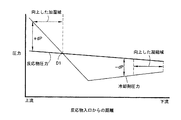
図3は、水の不均衡を緩和するのに利用できる二つの圧力プロファイルを示す。「圧力プロファイル」という用語は、反応物通路の長さに沿って測定した、酸化剤(または他の反応物)と冷却剤との相対圧力を意味する。圧力プロファイルグラフは、反応物流路内の位置における反応物圧力と、冷却剤流路の隣接または近接領域内の冷却剤圧力とを決定し、このプロセスを反応物流路の長さに沿って所望の位置において繰り返し、その結果をプロットすることによって生成される。 FIG. 3 shows two pressure profiles that can be used to alleviate the water imbalance. The term “pressure profile” refers to the relative pressure of the oxidant (or other reactant) and coolant, measured along the length of the reactant passage. The pressure profile graph determines the reactant pressure at a location in the reactant flow path and the coolant pressure in the adjacent or adjacent region of the coolant flow path, and this process is desired along the length of the reactant flow path. Generated by iterating at the position and plotting the result.
図3において、反応物流路内の酸化剤圧力は、酸化剤入口からの距離の関数として示される。第一の圧力プロファイルは、流れ絞り(35)のない図2の構成についてのものであり、冷却剤圧力(仮想線)と反応物圧力との間の関係である。第二の圧力プロファイルは、流れ絞り(35)を有する図2の構成についてのものであり、冷却剤圧力(点線)と反応物圧力との間の関係である。各圧力プロファイルにおいて、冷却剤圧力は、酸化剤流路入口の近くにおいて酸化剤圧力より高く、正の圧力差(+dP)を生じている。冷却剤と酸化剤両方とも、それらの入口からそれらの出口へと移動する間に、圧力降下を経験しているが、しかしながら、冷却剤の圧力降下は、酸化剤の圧力降下より大きい。従って、酸化剤出口の近くにおいて、冷却剤圧力は、酸化剤圧力より低く、負の圧力差(−dP)を生じる。 In FIG. 3, the oxidant pressure in the reactant flow path is shown as a function of distance from the oxidant inlet. The first pressure profile is for the configuration of FIG. 2 without the flow restriction (35) and is the relationship between the coolant pressure (phantom line) and the reactant pressure. The second pressure profile is for the configuration of FIG. 2 with a flow restriction (35) and is the relationship between coolant pressure (dotted line) and reactant pressure. In each pressure profile, the coolant pressure is higher than the oxidant pressure near the oxidant flow path inlet, creating a positive pressure difference (+ dP). Both the coolant and the oxidant experience a pressure drop while moving from their inlets to their outlets, however, the coolant pressure drop is greater than the oxidant pressure drop. Thus, near the oxidant outlet, the coolant pressure is lower than the oxidant pressure, resulting in a negative pressure differential (−dP).
第一の圧力プロファイル(仮想線)においては、正の圧力差(+dP)の大きさは、冷却剤流れおよび反応物流れがそれらの各入口からさらに遠くへ移動するにつれて、圧力差が移行区域または部分D1において中立すなわち「0」になるまで、低下する。冷却剤流れおよび反応物流れが移行区域を越えて移動する間に、圧力差は負(−dP)となり、これらの流れがその出口へと続く間に、負の圧力差の大きさは増加する。この圧力プロファイルは、反応物圧力および冷却剤圧力の滑らかで直線的な変化の結果として、反応物流路の長さに沿って相対的に滑らかで直線的な仕方で変化する。 In the first pressure profile (phantom line), the magnitude of the positive pressure difference (+ dP) is such that as the coolant flow and the reactant flow move further away from their respective inlets, the pressure difference becomes a transition zone or Decreases until neutral or “0” in portion D1. The pressure difference becomes negative (−dP) while the coolant and reactant streams move across the transition zone, and the magnitude of the negative pressure difference increases while these flows continue to their outlets. . This pressure profile changes in a relatively smooth and linear manner along the length of the reactant flow path as a result of smooth and linear changes in reactant and coolant pressures.
従って、移行区域または部分は、反応物流路の上流(+dP)区域を反応物流路の下流(−dP)区域から隔てる。移行区域は、特定の燃料電池設計の必要性に応じて所望のように配置できる。正の圧力差は、冷却剤流路(24)内の冷却剤水を、多孔質分配板(20)を通って酸化剤流路(22)の上流部分内へと流入させる。これによって、流入する酸化剤の流れを加湿するのに冷却剤が容易に利用できる、向上した加湿を伴う区域が提供される。負の圧力差は、水を、酸化剤流路(22)の下流部分から多孔質板(20)を通して、さらに冷却剤流路(22)内へと戻すように押しやることができ、それによって、電気化学反応で生じた過剰の液体水を除去し、反応物流路の下流部分に隣接する電極が冠水するのを防止する。 Thus, the transition zone or portion separates the upstream (+ dP) zone of the reactant channel from the downstream (-dP) zone of the reactant channel. The transition zone can be arranged as desired depending on the needs of a particular fuel cell design. A positive pressure differential causes the coolant water in the coolant channel (24) to flow through the porous distribution plate (20) and into the upstream portion of the oxidant channel (22). This provides an area with improved humidification where the coolant is readily available to humidify the incoming oxidant stream. The negative pressure differential can push water back from the downstream portion of the oxidant channel (22) through the porous plate (20) and back into the coolant channel (22), thereby Excess liquid water generated in the electrochemical reaction is removed to prevent the electrodes adjacent to the downstream portion of the reactant flow path from being flooded.
いくつかの用途では、向上した加湿(+dP)域は、冠水する傾向があり、従って電気化学反応に利用できないので、この領域をできる限り小さくするのが望ましくなり得る。この場合、酸化剤入口区域の近くの膜は、MEAの活性領域の一部とする必要がないであろうし、MEA内の電極をポリマーなどの材料で含浸させることにより反応物気体から隔てることができるであろう。これによって、いまだ加湿されていない反応物の流れに膜が曝されるのが防止されるであろうし、燃料が存在しない領域内の触媒の腐食が最小限に抑えられるであろう。 In some applications, it may be desirable to make this area as small as possible because the enhanced humidification (+ dP) area tends to flood and is therefore not available for electrochemical reactions. In this case, the membrane near the oxidant inlet area would not need to be part of the active area of the MEA and could be separated from the reactant gas by impregnating the electrode in the MEA with a material such as a polymer. It will be possible. This will prevent the membrane from being exposed to an unhumidified reactant stream and will minimize the corrosion of the catalyst in areas where there is no fuel.
向上した加湿域をできるだけ小さくするのを容易にするためには、例えば、先に説明した直線的で滑らかに変化する圧力プロファイルおよび冷却剤圧力を有するのではなくて、冷却剤圧力内に階段状の変化を提供することによって圧力プロファイル内に階段状の変化を有するのが望ましくなり得る。これは、MEA活性領域(37)の縁部に隣接する冷却剤流路内に流れ絞り(35)を配置することによって達成できる。流れ絞りまたは絞り装置(35)は、例えば、流路内に短い喉部または首状部分などの低減された断面領域を提供することによって、あるいは、短い距離の間、より少ない流路を通る複数の冷却剤流路を提供することによって、冷却剤圧力内に階段状の変化を提供する任意の装置または構造とすることができる。冷却剤圧力内の階段状の変化は、図3の点線により示されるように、反応物通路の上流部分から反応物通路の下流部分への圧力プロファイル内の階段状の変化となる。また、図3から明らかなように、移行区域は、反応物入口のより近く、点線上のD2へと移動して、MEA活性領域(37)の縁部に隣接して配置される流れ絞りの位置に一致する。 To facilitate minimizing the improved humidification region as much as possible, for example, instead of having the linear and smoothly varying pressure profile and coolant pressure described above, a stepped step in the coolant pressure is required. It may be desirable to have a step change in the pressure profile by providing a change in This can be achieved by placing a flow restrictor (35) in the coolant channel adjacent to the edge of the MEA active area (37). A flow restrictor or restrictor (35) can be provided, for example, by providing a reduced cross-sectional area in the flow path, such as a short throat or neck, or through fewer flow paths for a short distance. By providing the coolant flow path, any device or structure that provides a step change in coolant pressure can be provided. The step change in the coolant pressure results in a step change in the pressure profile from the upstream portion of the reactant passage to the downstream portion of the reactant passage, as shown by the dotted line in FIG. Also, as is apparent from FIG. 3, the transition zone moves closer to the reactant inlet, to D2 on the dotted line, and the flow restrictor located adjacent to the edge of the MEA active region (37). Match the position.
この水管理方法および圧力プロファイルは、MEAの燃料またはアノード(16)側でも使用できる。このような場合、反応物分配板(26)は、導電性多孔質材料で作成できるであろうし、燃料流れ通路(28)とは反対の側の冷却剤流れ通路(図示せず)を有することができるであろう。燃料(例えば、水素ガス)と冷却剤との間の圧力差は、図3に示される関係で維持でき、それによって、液体冷却剤水は、燃料流れ通路(28)へ供給されることができて、上流部分内の燃料を加湿し、それによって、過剰の液体水は、下流部分内の燃料流れ通路(28)から除去され得る。 This water management method and pressure profile can also be used on the fuel or anode (16) side of the MEA. In such a case, the reactant distribution plate (26) could be made of a conductive porous material and would have a coolant flow passage (not shown) on the opposite side of the fuel flow passage (28). Will be able to. The pressure difference between the fuel (eg, hydrogen gas) and the coolant can be maintained in the relationship shown in FIG. 3, so that liquid coolant water can be supplied to the fuel flow passage (28). Thus, the fuel in the upstream portion can be humidified so that excess liquid water can be removed from the fuel flow passageway (28) in the downstream portion.
図4は、酸化剤入口マニホールド(30)と酸化剤出口マニホールド(32)との間に曲がりくねった仕方で配置された酸化剤流れ流路または通路(22)を有する板(20)の実施態様を示す。冷却剤流れ流路または通路(24)は、冷却剤入口マニホールド(34)と冷却剤出口マニホールド(36)との間に曲がりくねった仕方で配置される。示される実施例においては、酸化剤通路および冷却剤通路両方とも、板(20)に亘って5つの経路を作成しているが、しかしながら、それより多い経路または少ない経路も、特定の燃料電池設計の必要性に応じて作成できる。酸化剤通路および冷却剤通路は、並流作動のために配置されており、すなわち、酸化剤および冷却剤両方とも、同じ方向に移動する。曲がりくねったパターンは、酸化剤および冷却剤の流れの速度および長さ両方を増加させるように使用できる。これは、上流区域内に正の圧力差と、下流区域内に負の圧力差とを有する圧力プロファイルを維持しながら、より高い圧力降下を促進できる。 FIG. 4 shows an embodiment of a plate (20) having an oxidant flow channel or passage (22) disposed in a serpentine manner between an oxidant inlet manifold (30) and an oxidant outlet manifold (32). Show. The coolant flow passage or passage (24) is disposed in a tortuous manner between the coolant inlet manifold (34) and the coolant outlet manifold (36). In the embodiment shown, both the oxidant and coolant passages create five paths across the plate (20), however, more or fewer paths may be used for a particular fuel cell design. Can be created according to the need of The oxidant and coolant passages are arranged for co-current operation, i.e. both the oxidant and the coolant travel in the same direction. The tortuous pattern can be used to increase both the oxidant and coolant flow rates and lengths. This can facilitate a higher pressure drop while maintaining a pressure profile having a positive pressure differential in the upstream zone and a negative pressure differential in the downstream zone.
図5は、酸化剤入口マニホールド(30)と酸化剤出口マニホールド(32)との間に曲がりくねった仕方で配置された酸化剤流れ流路または通路(22)を有する板(20)の実施態様を示す。冷却剤流れ流路または通路(24)は、冷却剤入口マニホールド(34)と冷却剤出口マニホールド(36)との間に曲がりくねった仕方で配置される。示される実施例においては、酸化剤通路および冷却剤通路両方とも、板に亘って5つの経路を作成しているが、しかしながら、それより多い経路または少ない経路も、特定の燃料電池設計の必要性に応じて作成できる。酸化剤通路および冷却剤通路は、向流作動のために配置されており、すなわち、酸化剤および冷却剤は、方向矢印により示されるように反対の方向に移動する。この構成においては、(+dP)の大きさは、図3に示される一定の低減とは反対に、酸化剤流路の部分のいくつかに沿って増加し得る。しかしながら、酸化剤流路の上流部分内に正の圧力差と、酸化剤流路の下流部分内に負の圧力差とを有する圧力プロファイルは、依然として維持される。 FIG. 5 shows an embodiment of a plate (20) having an oxidant flow channel or passage (22) disposed in a serpentine manner between an oxidant inlet manifold (30) and an oxidant outlet manifold (32). Show. The coolant flow passage or passage (24) is disposed in a tortuous manner between the coolant inlet manifold (34) and the coolant outlet manifold (36). In the example shown, both the oxidant and coolant passages create five paths across the plate; however, more or fewer paths may be necessary for a particular fuel cell design. Can be created according to The oxidant and coolant passages are arranged for counterflow operation, i.e., the oxidant and coolant move in opposite directions as indicated by the directional arrows. In this configuration, the magnitude of (+ dP) can increase along some of the portions of the oxidant flow path, as opposed to the constant reduction shown in FIG. However, a pressure profile with a positive pressure difference in the upstream portion of the oxidant flow path and a negative pressure difference in the downstream portion of the oxidant flow path is still maintained.
図6は、CSA(8)と液圧弁(38)とを有する燃料電池発電装置(6)の概略図である。冷却剤は、冷却剤入口ライン(39)を通ってCSAへ流入し、酸化剤は、酸化剤入口ライン(41)を通って流入し、燃料は、燃料入口ライン(43)を通って流入する。弁(38)は、冷却剤の出口圧力を制御するように、冷却剤水排出ライン(40)内に設置することができる。弁(38)は、冷却剤排出ライン内に設置された水圧ゲージ(42)などの冷却剤の性質を測定するゲージからの出力に応じて作動または制御できる。弁はまた、酸化剤排出ライン(45)内に設置されたガス圧ゲージ(44)などの酸化剤の性質を測定するゲージからの出力に応じて作動または制御できる。所望ならば、弁(38)は、冷却剤の性質と、酸化剤またはその他の反応物の性質との両方を測定する複数のゲージの組み合わせに従って制御できる。さまざまなゲージからの読み取り値は、例えば、冷却剤と酸化剤との各出口における冷却剤と酸化剤との間の圧力差を確認するために、マイクロプロセッサ(46)内で比較できる。所望ならば、空気圧式弁(図示せず)などの第二の圧力制御装置が、冷却剤ライン内の弁(38)に代えてまたはそれに加えて、酸化剤出口圧力を制御するのに酸化剤排出ライン(45)内に配置され得る。 FIG. 6 is a schematic diagram of a fuel cell power generator (6) having a CSA (8) and a hydraulic valve (38). Coolant flows into the CSA through the coolant inlet line (39), oxidant flows through the oxidant inlet line (41), and fuel flows through the fuel inlet line (43). . A valve (38) can be installed in the coolant water discharge line (40) to control the outlet pressure of the coolant. The valve (38) can be actuated or controlled in response to an output from a gauge that measures the properties of the coolant, such as a hydraulic gauge (42) installed in the coolant discharge line. The valve can also be activated or controlled in response to output from a gauge that measures the nature of the oxidant, such as a gas pressure gauge (44) installed in the oxidant discharge line (45). If desired, valve (38) can be controlled according to a combination of gauges that measure both the nature of the coolant and the nature of the oxidant or other reactant. The readings from the various gauges can be compared within the microprocessor (46), for example, to ascertain the pressure differential between the coolant and oxidant at each coolant and oxidant outlet. If desired, a second pressure control device such as a pneumatic valve (not shown) may be used to control the oxidant outlet pressure instead of or in addition to the valve (38) in the coolant line. It can be arranged in the discharge line (45).
図7は、二つの独立した冷却剤流れ通路(24a)および(24b)を有する板(20)の実施態様を示す。第一の通路(24a)は、第一の冷却剤入口マニホールド(34a)と第一の冷却剤出口マニホールド(36a)との間に曲がりくねった仕方で配置される。第二の冷却剤通路(24b)は、第二の冷却剤入口毎ホールド(34b)と第二の冷却剤出口万ホールド(36b)との間に曲がりくねった仕方で配置される。単一の酸化剤流れ通路(22)が、酸化剤入口マニホールド(30)と酸化剤出口マニホールド(32)との間に曲がりくねった仕方で配置される。第一の冷却剤通路(24a)は、酸化剤通路(22)の上流部分に隣接して配置され、第二の冷却剤通路(24b)は、酸化剤流れ通路の下流部分に隣接して配置される。 FIG. 7 shows an embodiment of a plate (20) having two independent coolant flow passages (24a) and (24b). The first passage (24a) is arranged in a tortuous manner between the first coolant inlet manifold (34a) and the first coolant outlet manifold (36a). The second coolant passage (24b) is arranged in a meandering manner between the second coolant inlet per-hold (34b) and the second coolant outlet tens hold (36b). A single oxidant flow passage (22) is disposed in a tortuous manner between the oxidant inlet manifold (30) and the oxidant outlet manifold (32). The first coolant passage (24a) is disposed adjacent to the upstream portion of the oxidant passage (22), and the second coolant passage (24b) is disposed adjacent to the downstream portion of the oxidant flow passage. Is done.
図7は、冷却剤流路のうちの一つの二つの経路の間に挟み込まれた、酸化剤流路の各経路を示す。例えば、酸化剤流路経路(22a)は、冷却剤経路(25a)と(25b)との間にある。必要または所望ならば、冷却剤経路のうちの一つは、隣接する酸化剤流路に比較して圧力プロファイルに対してより大きな影響を有するように、酸化剤経路のより近くに配置できる。従って、並流構成が望ましい場合は、酸化剤と同じ方向に移動する流れを有する冷却剤経路は、酸化剤流れの方向とは反対に移動する流れを有する冷却剤経路に比較して、酸化剤流路のより近くに配置できる。例えば、図7においては、冷却剤経路(25b)は、並流特性を達成するように酸化剤経路(22a)のより近くに配置できる。 FIG. 7 shows each path of the oxidant flow path sandwiched between two paths of one of the coolant flow paths. For example, the oxidant flow path (22a) is between the coolant paths (25a) and (25b). If necessary or desired, one of the coolant paths can be placed closer to the oxidant path so as to have a greater effect on the pressure profile compared to the adjacent oxidant flow path. Thus, when a co-flow configuration is desired, a coolant path having a flow that travels in the same direction as the oxidant is compared to a coolant path that has a flow that travels opposite to the direction of the oxidant flow. It can be placed closer to the flow path. For example, in FIG. 7, the coolant path (25b) can be placed closer to the oxidant path (22a) to achieve cocurrent characteristics.
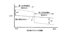
図8は、図7に示される実施態様の第一の冷却剤通路(24a)、第二の冷却剤通路(24b)、および酸化剤通路(22)内の圧力間の、並流作動のための圧力プロファイルを示す。第一の通路(24a)内の冷却剤圧力は、酸化剤圧力より高く、従って、液体冷却剤水は、酸化剤を加湿するように、多孔質板を介して酸化剤通路(22)の上流部分内へ供給される。第二の冷却剤通路(24b)内の冷却剤圧力は、酸化剤圧力より低く、それによって、流路(22)の下流部分内の過剰の液体水は、多孔質板を介して冷却剤流路(24b)内へ押し込まれる。この構成の利点は、各冷却剤通路内の圧力が、互いに独立して制御され得ること、すなわち、一方の通路内の圧力が、他方の通路内の圧力に影響を及ぼさずに変更され得ることである。図8に示される圧力プロファイルはまた、階段状の変化が圧力プロファイルにおいて望ましい用途において、有利となり得る。 FIG. 8 is for co-current operation between the pressure in the first coolant passage (24a), the second coolant passage (24b), and the oxidant passage (22) of the embodiment shown in FIG. The pressure profile of is shown. The coolant pressure in the first passage (24a) is higher than the oxidant pressure, so the liquid coolant water is upstream of the oxidant passage (22) through the porous plate so as to humidify the oxidant. Supplied into the part. The coolant pressure in the second coolant passage (24b) is lower than the oxidant pressure, so that excess liquid water in the downstream portion of the flow path (22) is passed through the porous plate to the coolant flow. It is pushed into the path (24b). The advantage of this configuration is that the pressure in each coolant passage can be controlled independently of each other, i.e. the pressure in one passage can be changed without affecting the pressure in the other passage. It is. The pressure profile shown in FIG. 8 can also be advantageous in applications where a step change is desired in the pressure profile.
図9は、第一および第二の冷却剤通路(24a)および(24b)が、通路(22)内の酸化剤流れの方向全体に対する向流作動を提供するように配置される、実施態様を示す。向流作動では、酸化剤流れと反対の方向に移動する流れを有する冷却剤経路は、酸化剤流れと同じ方向に移動する流れを有する冷却剤経路に比較して、酸化剤経路のより近くに配置され得る。酸化剤通路は、酸化剤入口マニホールド(30)と酸化剤出口マニホールド(32)との間に曲がりくねった仕方で配置される。第一の冷却剤通路(24a)は、第一の冷却剤入口マニホールド(34a)および第一の冷却剤出口マニホールド(36a)と共に配置される。第二の冷却剤通路(24b)は、第二の冷却剤入口マニホールド(34b)および第二の冷却剤出口マニホールド(36b)と共に配置される。 FIG. 9 shows an embodiment in which the first and second coolant passages (24a) and (24b) are arranged to provide countercurrent operation for the entire direction of oxidant flow in the passage (22). Show. In counterflow operation, a coolant path having a flow moving in the opposite direction of the oxidant flow is closer to the oxidant path compared to a coolant path having a flow moving in the same direction as the oxidant flow. Can be placed. The oxidant passage is disposed in a tortuous manner between the oxidant inlet manifold (30) and the oxidant outlet manifold (32). The first coolant passage (24a) is disposed with the first coolant inlet manifold (34a) and the first coolant outlet manifold (36a). The second coolant passage (24b) is disposed with the second coolant inlet manifold (34b) and the second coolant outlet manifold (36b).
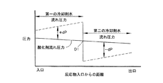
図10は、向流作動を有する、図9に示される実施対応の第一の冷却剤通路(24a)、第二の冷却剤通路(24b)、および酸化剤通路(22)内の圧力間の圧力プロファイルをグラフで示す。正の圧力差の大きさは、酸化剤流路の上流部分内において酸化剤流れの方向に増加し、一方、負の圧力差の大きさは、酸化剤流路の下流部分内において酸化剤流れの方向に減少する。しかしながら、上流部分内の正の圧力差と下流部分内の負の圧力差とを有する圧力プロファイルは、依然として維持される。 FIG. 10 shows the pressure between the first coolant passage (24a), the second coolant passage (24b) and the oxidant passage (22) corresponding to the implementation shown in FIG. The pressure profile is shown graphically. The magnitude of the positive pressure difference increases in the direction of oxidant flow within the upstream portion of the oxidant flow path, while the magnitude of the negative pressure difference increases with oxidant flow within the downstream portion of the oxidant flow path. Decrease in the direction of. However, a pressure profile with a positive pressure difference in the upstream portion and a negative pressure difference in the downstream portion is still maintained.
図11は、二つの独立した冷却剤流路(24a)および(24b)と、酸化剤流路(22)とを有する燃料電池装置(10)の実施態様を示す。上述した流路は、流路(24a)が、酸化剤流路の上流部分に隣接し、流路(24b)が、酸化剤流路の下流部分に隣接するように、配置される。冷却剤は、冷却剤入口ライン(39a)および(39b)を通って燃料電池装置へ流入し、酸化剤は、酸化剤入口ライン(41)を通って流入し、燃料は、燃料入口ライン(43)を通って流入する。流路(24a)は、行き止まりであり、一方、流路(24b)は、入口マニホールドおよび出口マニホールド(図示せず)の間に延在する。行き止まりの構成においては、冷却剤流路(24a)は、出口マニホールド内へと移行せずに、位置(48)において、取り囲む板構造内で終了する。行き止まりの出口を有する流路においては、全ての冷却剤は通常、板材料を通して、酸化剤通路内へ押しやられることになる。 FIG. 11 shows an embodiment of a fuel cell device (10) having two independent coolant channels (24a) and (24b) and an oxidant channel (22). The channel described above is arranged such that the channel (24a) is adjacent to the upstream portion of the oxidant channel and the channel (24b) is adjacent to the downstream portion of the oxidant channel. The coolant flows into the fuel cell device through the coolant inlet lines (39a) and (39b), the oxidant flows through the oxidant inlet line (41), and the fuel flows into the fuel inlet line (43). ) The flow path (24a) is a dead end, while the flow path (24b) extends between an inlet manifold and an outlet manifold (not shown). In the dead end configuration, the coolant channel (24a) does not move into the outlet manifold, but ends in the surrounding plate structure at position (48). In a flow path having a dead end outlet, all the coolant will normally be forced through the plate material and into the oxidant passage.
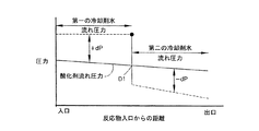
図12は、図11の実施態様の、冷却剤流路(24a)および(24b)内の冷却剤圧力と、流路(22)内の酸化剤圧力の間の圧力プロファイルをグラフで示す。冷却剤圧力は、行き止まりの流路(24a)内においては相対的に一定であり、全ての冷却剤水は、酸化剤流路の上流部分を加湿するように、多孔質板を通って酸化剤通路(22)内へ流れ込む。行き止まりの構成は、例えば、排出ラインおよび圧力制御弁などの下流部材を除去するのが望ましい場合に使用され得る。例えば、行き止まりの通路内の流入冷却剤の流量および圧力は、簡単な計量ポンプ(図示せず)で制御できる。しかしながら、酸化剤流路ばかりでなく、行き止まりでない第二の冷却剤流路に下流部材を含むのが、依然として望ましいものとなり得るであろう。そのような部材は、例えば、液圧弁(38)、冷却剤水排出ライン(40)、水圧ゲージ(42)、酸化剤圧力ゲージ(44)、およびマイクロプロセッサ(46)を含むことができる。 FIG. 12 graphically illustrates the pressure profile between the coolant pressure in the coolant channels (24a) and (24b) and the oxidant pressure in the channel (22) for the embodiment of FIG. The coolant pressure is relatively constant within the dead-end channel (24a), and all coolant water passes through the porous plate to humect the upstream portion of the oxidant channel. It flows into the passage (22). A dead end configuration may be used when it is desirable to remove downstream members such as, for example, discharge lines and pressure control valves. For example, the flow rate and pressure of the incoming coolant in the dead end passage can be controlled with a simple metering pump (not shown). However, it may still be desirable to include a downstream member in the non-dead end second coolant channel as well as the oxidant channel. Such members can include, for example, a hydraulic valve (38), a coolant water discharge line (40), a water pressure gauge (42), an oxidant pressure gauge (44), and a microprocessor (46).
図示したように、図11の実施態様は、二つの冷却剤ポンプ(図示せず)を有することができ、一つは通路(24a)に流入する冷却剤用であり、一つは通路(24b)に流入する冷却剤用である。所望ならば、単一のポンプを使用できる。そのような実施態様においては、ポンプは、通路(24b)に冷却剤を提供し、通路(24b)から排出された冷却剤は、弁および熱交換器(図示せず)などといった適切な部材の組み合わせを介して、通路(24a)に戻るように循環され得る。この単一のポンプによる方法は、二つまたは三つ以上の冷却剤ループを有する他の実施態様において、たとえ冷却剤流路の一つが、行き止まりでないとしても、使用できる。 As shown, the embodiment of FIG. 11 can have two coolant pumps (not shown), one for the coolant entering the passage (24a) and one for the passage (24b). ) For coolant flowing into If desired, a single pump can be used. In such an embodiment, the pump provides coolant to the passage (24b) and the coolant discharged from the passage (24b) is supplied by suitable components such as valves and heat exchangers (not shown). Through the combination, it can be circulated back to the passage (24a). This single pump method can be used in other embodiments having two or more coolant loops, even if one of the coolant channels is not dead-end.
図13は、三層の材料から成る板(20)の実施態様を示す。第一または中心の層(20a)は、導電性多孔質材料で作成された平らな板であり、外側層(20b)と(20c)との間に挟まれている。第二および第三の層も、導電性多孔質材料で作成されており、穿孔された酸化剤流れ流路(22)と、冷却剤流れ流路(24)とを有することができる。層(20a)内の細孔径は通常、約10kPa以下の泡圧力を有するシステム内において平均で10ミクロン未満とすることができる。外側層(20b)および(20c)の細孔径は、第一の層(20a)内の細孔径より大きい。これは、結果として、第一または中心の層内に十分な濡れシールを維持しながら、第二および第三の層を通るより良好な水透過性となる。この構成によって、例えば、構造的な強化に必要な場合に、望ましい水透過性の特性を犠牲にせずに、外側層の厚みを増加させることができる。 FIG. 13 shows an embodiment of a plate (20) made of three layers of material. The first or central layer (20a) is a flat plate made of a conductive porous material and is sandwiched between outer layers (20b) and (20c). The second and third layers are also made of a conductive porous material and can have perforated oxidant flow channels (22) and coolant flow channels (24). The pore size in layer (20a) can typically be less than 10 microns on average in a system having a bubble pressure of about 10 kPa or less. The pore diameters of the outer layers (20b) and (20c) are larger than the pore diameters in the first layer (20a). This results in better water permeability through the second and third layers while maintaining a sufficient wet seal within the first or center layer. This configuration can increase the thickness of the outer layer without sacrificing desirable water permeability characteristics, for example, when required for structural reinforcement.
図14は、カソード側の反応物分配板(図1の部材20を参照のこと)と、アノード側の反応物分配板(図1の部材26を参照のこと)とが、単一の板構造(52)に一体化される実施態様を示す。板(52)は、五層を有する。層(52a)および52b)の二つは、導電性多孔質材料で作成される。残りの三層は、カソード層(52c)、中間層(52d)、およびアノード層(52e)である。これらは、酸化剤流路(22)、冷却剤流路(24)、および燃料流路(28)がそれぞれ穿孔されている。穿孔された流路または通路を有する三つの板の使用は、二つの反応物分配板が、単一のユニットとして形成されており、流路を機械加工する必要がないので、より短い製造時間を提供する。
FIG. 14 shows that a cathode side reactant distribution plate (see
図15は、CSA(8)と冷却剤水ループ(53)とを有する燃料電池発電装置(6)の概略図である。ループ(53)は、冷却剤水排出ライン(40)内に直列に水ポンプ(54)と、水蓄積装置(56)と、熱交換器(58)とを有することができる。蓄積装置(56)は、圧縮空気供給ライン(60)と、背圧弁(62)とを備えることができる。 FIG. 15 is a schematic diagram of a fuel cell power generator (6) having a CSA (8) and a coolant water loop (53). The loop (53) can have a water pump (54), a water storage device (56), and a heat exchanger (58) in series in the coolant water discharge line (40). The accumulator (56) can comprise a compressed air supply line (60) and a back pressure valve (62).
図16は、図15の実施態様における冷却剤水と酸化剤気体との間の圧力プロファイルをグラフで示す。水ポンプ(54)は、CSA(8)から冷却剤を引張りかつ冷却剤出口における圧力を周囲圧力より低く保つ低い圧力条件を生成する。蓄積装置(56)は、圧縮空気供給ライン(60)を介して圧縮され、その圧力は、背圧弁(62)によって制御される。蓄積装置からの水は、全体のシステムの水管理を助けるように、熱交換器(58)を介してCSA内へと戻すことができる。この構成は、位置D1において移行部分によって隔てられる、酸化剤流路の上流部分内の(+dP)と、酸化剤流路の下流部分内の(−dP)とを有する圧力プロファイルを実現する。この実施態様は、必要とされる酸化剤入口圧力必要量を低減でき、従って、寄生電力必要量から生じる損失を低減する。 FIG. 16 graphically illustrates the pressure profile between the coolant water and the oxidant gas in the embodiment of FIG. The water pump (54) creates a low pressure condition that pulls the coolant from the CSA (8) and keeps the pressure at the coolant outlet below ambient pressure. The accumulator (56) is compressed via a compressed air supply line (60), the pressure of which is controlled by a back pressure valve (62). Water from the accumulator can be returned into the CSA via a heat exchanger (58) to assist in water management of the entire system. This configuration achieves a pressure profile having (+ dP) in the upstream portion of the oxidant flow path and (−dP) in the downstream portion of the oxidant flow path, separated by a transition portion at position D1. This embodiment can reduce the required oxidant inlet pressure requirement, thus reducing losses resulting from parasitic power requirements.
図17は、流れ絞り(35)を備える冷却剤流路(24)を有する板(20)の実施態様の概略図である。冷却剤流路は、板(20)に亘って二つの経路を作成し、冷却剤入口マニホールド(34)から冷却剤出口マニホールド(36)へ延在する。酸化剤流路(22)は、酸化剤入口マニホールド(30)から流れ反転マニホールド(66)へ延在する。流れ反転マニホールド内へ注ぐ空気または酸素は、流路22aを介して酸化剤出口マニホールドへ運ばれる。流れ絞り(35)は、必要とされる向上した加湿域の大きさに応じて、冷却剤通路内の所望の位置に配置される。図17に示されるように、それは、上流の向上した加湿域を冷却剤通路の下流部分より小さくするように、出口(36)に比較して、冷却剤入口(34)のより近くに配置され得る。
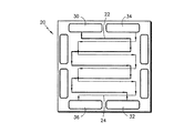
FIG. 17 is a schematic view of an embodiment of a plate (20) having a coolant flow path (24) with a flow restriction (35). The coolant flow path creates two paths across the plate (20) and extends from the coolant inlet manifold (34) to the coolant outlet manifold (36). The oxidant flow path (22) extends from the oxidant inlet manifold (30) to the flow reversal manifold (66). Air or oxygen that pours into the flow reversing manifold is carried through
図17に示される実施態様の利点は、流路構成が、酸化剤出口(32)の近くに酸化剤の向上した冷却を設けることができることである。冷却剤は、冷却剤入口マニホールド(34)を通り過ぎた直後で向上した加湿域に重なる冷却剤入口区域(61)を通って移動し、そこで冷却剤は入口マニホールド(30)から流入する相対的に乾燥した反応物内へ蒸発する。蒸発は、冷却剤の温度を低下させる。 An advantage of the embodiment shown in FIG. 17 is that the flow path configuration can provide improved cooling of the oxidant near the oxidant outlet (32). The coolant travels through the coolant inlet section (61) that overlaps the enhanced humidification zone immediately after passing through the coolant inlet manifold (34), where the coolant flows relatively from the inlet manifold (30). Evaporate into the dry reaction. Evaporation reduces the temperature of the coolant.
次いで、冷却剤は、流れ絞り(35)を通過した後に冷却剤流路の中間区域(64)へ流入し、そこでそれは、蒸発冷却効果に起因してそれが冷却剤入口区域へ流入したときにそうであったより低温になる。酸化剤流路および冷却剤流路は、より低温の冷却剤が空気出口マニホールド(32)の近くに存在するように、配置され、その結果、酸化剤出口の近くの空気の向上した冷却が得られる。これは、空気出口(32)近くにおいて空気の流れからより多量の水蒸気の凝縮を生じさせることができ、それは、負の圧力差(−dP)によって冷却剤ループ内へと押し戻されることができ、それによって、システム内により多量の水を保持し、燃料電池発電装置全体の水バランスの維持を助ける。図17の実施態様を用いて達成され得る圧力プロファイルは、図18に示される。 The coolant then flows through the flow restrictor (35) and then flows into the middle section (64) of the coolant flow path where it flows into the coolant inlet section due to evaporative cooling effects. It will be cooler than it was. The oxidant and coolant channels are positioned so that the cooler coolant is near the air outlet manifold (32), resulting in improved cooling of the air near the oxidant outlet. It is done. This can cause more water vapor condensation from the air flow near the air outlet (32), which can be pushed back into the coolant loop by a negative pressure differential (−dP), Thereby, more water is retained in the system, helping to maintain the water balance of the entire fuel cell power plant. A pressure profile that can be achieved using the embodiment of FIG. 17 is shown in FIG.
図19は、冷却剤排出ライン(40)内に設置された気体検出器(68)と、酸化剤排出ライン(45)内に設置された湿度検出器(70)とを有する燃料電池発電装置(6)の実施態様を示す。湿度検出器は、図17に示される方向転換マニホールド(66)内に配置することもできる。気体検出器は、例えば、導電性検出器または超音波流量計とすることができる。冷却剤出口圧力は、気体検出手段からの信号に応じて弁(38)によって調節され得る。従って、例えば、負の圧力差(冷却剤圧力が酸化剤圧力より低い場合)の大きさは、気体が冷却剤排出物内で検出される場合、低減されることができる。冷却剤流れの出口圧力はまた、例えば、排出された酸化剤中に低い湿度が検出された場合、正の圧力差(冷却剤圧力が酸化剤圧力より高い場合)の大きさを増加させるように、湿度検出器からの信号に基づいて制御され得る。空気圧式弁(図示せず)も、酸化剤排出ライン(45)内に配置されることができ、酸化剤および液体冷却剤の測定された一つまたは複数の性質に応じて、圧力プロファイルを制御するのに同様な仕方で使用されることができる。 FIG. 19 shows a fuel cell power generation device having a gas detector (68) installed in the coolant discharge line (40) and a humidity detector (70) installed in the oxidant discharge line (45). The embodiment of 6) is shown. The humidity detector can also be placed in the turning manifold (66) shown in FIG. The gas detector can be, for example, a conductivity detector or an ultrasonic flow meter. The coolant outlet pressure can be adjusted by valve (38) in response to a signal from the gas detection means. Thus, for example, the magnitude of the negative pressure difference (if the coolant pressure is lower than the oxidant pressure) can be reduced if gas is detected in the coolant discharge. The outlet pressure of the coolant flow also increases the magnitude of the positive pressure difference (if the coolant pressure is higher than the oxidant pressure), for example if low humidity is detected in the discharged oxidant Can be controlled based on the signal from the humidity detector. A pneumatic valve (not shown) can also be placed in the oxidant discharge line (45) to control the pressure profile depending on one or more measured properties of the oxidant and liquid coolant. Can be used in a similar manner.
本発明の特徴部を有するシステムの作動においては、水素、および空気または酸素などの反応物は、圧縮機、送風機、ファン、および圧縮空気ボンベ(図示せず)などといった当業者に知られた手段を用いて所望の入口圧力において入口マニホールドへ供給され得る。同様に、液体冷却剤は、ポンプ(図示せず)、および圧縮空気により作動される蓄積装置などといった当業者に知られた手段を用いて所望の入口圧力において入口マニホールドへ供給され得る。CSAは、所望の圧力降下を与えるような大きさとされた反応物流路および冷却剤流路を用いて設計できる。流路の大きさに加えて、出口圧力を制御する手段を、反応物出口および冷却剤出口に配置できる。このような手段は、例えば、背圧を生成するための弁、および、出口において低い圧力条件を生成するのに使用されるポンプまたは圧縮機、その他を含むことができる。 In operation of the system having the features of the present invention, hydrogen and reactants such as air or oxygen are means known to those skilled in the art such as compressors, blowers, fans, and compressed air cylinders (not shown). Can be supplied to the inlet manifold at the desired inlet pressure. Similarly, liquid coolant can be supplied to the inlet manifold at a desired inlet pressure using means known to those skilled in the art, such as a pump (not shown) and a storage device operated by compressed air. The CSA can be designed with reactant and coolant channels that are sized to provide the desired pressure drop. In addition to the size of the flow path, means for controlling the outlet pressure can be located at the reactant outlet and the coolant outlet. Such means may include, for example, a valve for generating back pressure and a pump or compressor used to generate low pressure conditions at the outlet, and the like.
反応物および冷却剤の入口圧力および出口圧力は、反応物流路の上流部分内の正の圧力差と、反応物流路の下流部分内の負の圧力差とを有する圧力プロファイルを提供する上述した方法のさまざまな組み合わせを用いて制御される。上述した方法のさまざまな組み合わせは、正の圧力差および負の圧力差のその大きさを調節するように、かつ、燃料電池内の適正な水バランスを維持するのを促進する圧力プロファイルを提供するように、利用できる。このような調節は、燃料電池に掛けられる変化するまたは過渡的な負荷要求量にばかりでなく、反応物および冷却剤の測定された性質に応じて、行うことができる。必要または所望ならば、上述した手段のさまざまな組み合わせを、当業者に知られた仕方によって、一つまたは複数のマイクロプロセッサに接続してそのマイクロプロセッサによって制御することができる。 Reactant and coolant inlet and outlet pressures provide a pressure profile having a positive pressure differential in the upstream portion of the reactant flow path and a negative pressure differential in the downstream portion of the reactant flow path. Controlled using various combinations. Various combinations of the above-described methods provide a pressure profile that adjusts the magnitude of the positive and negative pressure differences and facilitates maintaining proper water balance within the fuel cell. As available. Such adjustments can be made depending on the measured properties of the reactants and coolant as well as the changing or transient load requirements imposed on the fuel cell. If necessary or desired, various combinations of the above-described means can be connected to and controlled by one or more microprocessors in a manner known to those skilled in the art.
さまざまな変更および付加を、本発明の精神および範囲から逸脱せずに、ここに説明した実施態様に行うことができる。例えば、ここに説明した実施態様は、主に酸化剤流れ板に関して議論したとはいえ、それらは、燃料流れ板上にも使用できる。同様に、圧力プロファイルは、主に冷却剤と酸化剤との間の圧力差に関して説明したとはいえ、圧力プロファイルは、冷却剤と燃料との間にも確立できる。さらに、例えば、内部マニホールドまたは外部マニホールド(あるいは、両方の組み合わせ)を使用するかどうか、および、流れ区域内に使用される経路の数などといった、設計の詳細は、特定の燃料電池発電装置設計の必要性に従って変更できる。さらに、冷却剤は、ここでは液体水であるとして説明したとはいえ、冷却剤を、PEM型燃料電池内で使用するのに適した不凍液溶液とすることができることも考えられる。 Various changes and additions can be made to the embodiments described herein without departing from the spirit and scope of the present invention. For example, although the embodiments described herein were discussed primarily with respect to oxidant flow plates, they can also be used on fuel flow plates. Similarly, although the pressure profile has been described primarily with respect to the pressure difference between the coolant and the oxidant, the pressure profile can also be established between the coolant and the fuel. In addition, design details such as whether internal manifolds or external manifolds (or a combination of both) are used, and the number of paths used within the flow area, are specific to the particular fuel cell generator design. You can change according to your needs. Furthermore, although the coolant has been described here as liquid water, it is also conceivable that the coolant can be an antifreeze solution suitable for use in a PEM type fuel cell.
Claims (19)
反応物通路入口に隣接する上流部分と、反応物通路出口に隣接する下流部分とを有する少なくとも一つの反応物通路内へ反応物を流入させ、
少なくとも一つの液体通路内へ液体を流入させ、
前記上流部分内に正の圧力差と、負の圧力差前記下流部分とを提供するように圧力プロファイルを制御する、
ことを含み、正の圧力差が、液体通路内の液体を多孔質材料を通して、前記上流部分の少なくとも一部の中へと押し込む、ことを特徴とする方法。 At least one reactant passage for providing a reactant to the electrolyte, at least one liquid passage, and a liquid permeable and electrically conductive porous material separating at least one reactant passage and at least one liquid passage; A method of operating a fuel cell power generator having
Flowing the reactant into at least one reactant passage having an upstream portion adjacent to the reactant passage inlet and a downstream portion adjacent to the reactant passage outlet;
Flowing liquid into at least one liquid passage;
Controlling the pressure profile to provide a positive pressure difference in the upstream portion and a negative pressure difference in the downstream portion;
And the positive pressure differential pushes the liquid in the liquid passage through the porous material and into at least a portion of the upstream portion.
第一の電極と、第二の電極とを有する膜電極アッセンブリと、
膜電極アッセンブリに隣接する液体透過性の多孔質材料を有し、さらに、第一の電極に面する第一の反応物流路と、多孔質材料によって第一の反応物流路から隔てられた液体冷却剤流路とを有する、反応物分配板と、
を備え、
第一の反応物流路は、上流部分と、下流部分と、上流部分と下流部分との間の移行部分とを有し、
反応物分配板は、圧力プロファイル内に階段状の変化を提供する階段状化手段を有し、この階段状化手段は、反応物分配板内に配置され、それによって、階段状の変化が、移行部分に隣接して生じる、
ことを特徴とする燃料電池発電装置。 A fuel cell power plant capable of operating with a first reactant, a second reactant, and a liquid coolant having an improved humidification system comprising:
A membrane electrode assembly having a first electrode and a second electrode;
A liquid permeable porous material adjacent to the membrane electrode assembly, further comprising a first reactant channel facing the first electrode, and a liquid cooling separated from the first reactant channel by the porous material A reactant distribution plate having an agent flow path;
With
The first reactant flow path has an upstream portion, a downstream portion, and a transition portion between the upstream portion and the downstream portion,
The reactant distribution plate has stepped means for providing a stepped change in the pressure profile, the stepped means being disposed in the reactant distribution plate, whereby the stepped change is Occurs adjacent to the transition,
A fuel cell power generator characterized by that.
反応物を反応物流路内へ流し、
冷却剤を冷却剤流路内へ流し、
された加湿域を生成するように反応物流路の上流部分内に正の圧力差を提供し、
反応物流路の移行部分内に中立の圧力差を提供し、
反応物流路の下流部分内に負の圧力差を提供する、
ことを含むことを特徴とする方法。 A method of operating a fuel cell power plant having an MEA having an active region and a plate comprising a porous material adjacent to the MEA, the plate having a reactant channel and a coolant channel. The reactant flow path supplies the reactant to the active region and is separated from the coolant flow path by a porous material, the method comprising:
Flow the reactants into the reactant flow path,
Flow coolant into the coolant flow path,
Providing a positive pressure differential within the upstream portion of the reactant flow path to produce a humidified zone,
Provides a neutral pressure differential within the transition portion of the reactant flow path,
Providing a negative pressure differential in the downstream portion of the reactant flow path,
A method comprising:
Applications Claiming Priority (2)
| Application Number | Priority Date | Filing Date | Title |
|---|---|---|---|
| US10/309,971 US6869709B2 (en) | 2002-12-04 | 2002-12-04 | Fuel cell system with improved humidification system |
| PCT/US2003/037296 WO2004051818A2 (en) | 2002-12-04 | 2003-11-21 | Fuel cell system with improved humidification system |
Publications (2)
| Publication Number | Publication Date |
|---|---|
| JP2006509332A true JP2006509332A (en) | 2006-03-16 |
| JP4624799B2 JP4624799B2 (en) | 2011-02-02 |
Family
ID=32467954
Family Applications (1)
| Application Number | Title | Priority Date | Filing Date |
|---|---|---|---|
| JP2004557248A Expired - Fee Related JP4624799B2 (en) | 2002-12-04 | 2003-11-21 | Fuel cell system with improved humidification system |
Country Status (5)
| Country | Link |
|---|---|
| US (2) | US6869709B2 (en) |
| JP (1) | JP4624799B2 (en) |
| AU (1) | AU2003295778A1 (en) |
| DE (1) | DE10393841T5 (en) |
| WO (1) | WO2004051818A2 (en) |
Cited By (2)
| Publication number | Priority date | Publication date | Assignee | Title |
|---|---|---|---|---|
| JP2007184214A (en) * | 2006-01-10 | 2007-07-19 | Toshiba Fuel Cell Power Systems Corp | Fuel cell separator |
| JP2015522934A (en) * | 2012-07-20 | 2015-08-06 | バラード パワー システムズ インコーポレイテッド | Fuel cell coolant flow field configuration |
Families Citing this family (43)
| Publication number | Priority date | Publication date | Assignee | Title |
|---|---|---|---|---|
| DE10119339B4 (en) * | 2001-04-20 | 2006-03-30 | Fraunhofer-Gesellschaft zur Förderung der angewandten Forschung e.V. | Fuel cell system and method for pressure regulation in fuel cell systems and use of the fuel cell system |
| US20050014037A1 (en) * | 2002-12-04 | 2005-01-20 | Chris Boyer | Fuel cell with recombination catalyst |
| JP4180404B2 (en) * | 2003-03-05 | 2008-11-12 | アイシン精機株式会社 | Fuel cell, oxidizer flow plate |
| WO2005043666A1 (en) * | 2003-11-03 | 2005-05-12 | Greenlight Power Technologies, Inc. | An electrochemical cell cooling system |
| JP4753599B2 (en) * | 2005-03-17 | 2011-08-24 | 本田技研工業株式会社 | Fuel cell |
| WO2007070047A2 (en) * | 2005-12-14 | 2007-06-21 | Utc Fuel Cells, Llc | Oxygen-consuming zero-gap electrolysis cells with porous/solid plates |
| US7851096B2 (en) * | 2005-12-27 | 2010-12-14 | Plug Power Inc. | Humidifying a reactant flow of a fuel cell system |
| US20100167140A1 (en) * | 2005-12-30 | 2010-07-01 | Balliet Ryan J | Response to Ingestion of Gas Into Fuel Cell Coolant |
| US20070154744A1 (en) * | 2005-12-30 | 2007-07-05 | Darling Robert M | Fuel cell coolant bubble control |
| US20070207362A1 (en) * | 2006-03-03 | 2007-09-06 | Andreas Koenekamp | Freeze capable compact fuel cell system with improved humidification and removal of excess water and trapped nitrogen |
| EP1992030A2 (en) * | 2006-03-07 | 2008-11-19 | AFC Energy PLC | Electrodes of a fuel cell |
| GB0604597D0 (en) * | 2006-03-07 | 2006-04-19 | Dfc Energy Ltd | A fuel cell assembly |
| GB0604598D0 (en) * | 2006-03-07 | 2006-04-19 | Dfc Energy Ltd | Improvements in and relating to fuel cells |
| US7479335B2 (en) * | 2006-06-29 | 2009-01-20 | Plug Power Inc. | Anode humidification |
| EP2044643A4 (en) * | 2006-07-25 | 2009-10-28 | Utc Power Corp | Water management for a fuel cell |
| JP5247719B2 (en) * | 2006-12-19 | 2013-07-24 | ユーティーシー パワー コーポレイション | Variable fuel pressure control for fuel cells |
| US20100075199A1 (en) * | 2006-12-20 | 2010-03-25 | Darling Robert M | Hydrophobic layer for a fuel cell |
| WO2008088310A1 (en) * | 2006-12-27 | 2008-07-24 | Utc Power Corporation | Wettable gas diffusion layer for a wet seal in a fuel cell |
| US20080160366A1 (en) * | 2006-12-29 | 2008-07-03 | Allen Glenn M | Porous plate for a fuel cell |
| DE112008003998T5 (en) * | 2008-08-29 | 2011-07-21 | UTC Power Corp., Conn. | A fuel cell device comprising a porous cooling plate assembly having a barrier layer |
| DE112008004031T5 (en) * | 2008-10-06 | 2011-09-29 | Utc Power Corp. | Voltage-based fluid sensor for a fuel cell stack system |
| CN102106026A (en) | 2008-10-10 | 2011-06-22 | 丰田自动车株式会社 | Fuel cell |
| WO2010077250A1 (en) * | 2009-01-05 | 2010-07-08 | Utc Power Corporation | Fluid flow assemblies for, and in, fuel cell stacks |
| US9196913B2 (en) | 2009-01-08 | 2015-11-24 | Audi Ag | Multiple transition flow field and method |
| US8722276B2 (en) | 2009-01-08 | 2014-05-13 | United Technologies Corporation | Multiple transition flow field and method |
| CN103503211B (en) * | 2010-10-06 | 2016-03-23 | 奥迪股份公司 | Core-enhanced evaporatively cooled fuel cell with water passages |
| US10277095B2 (en) | 2010-12-27 | 2019-04-30 | Audi Ag | Cooling arrangement using an electrochemical cell |
| US8884578B2 (en) | 2011-02-07 | 2014-11-11 | United Technologies Corporation | Method and system for operating a flow battery system based on energy costs |
| US9123962B2 (en) | 2011-02-07 | 2015-09-01 | United Technologies Corporation | Flow battery having electrodes with a plurality of different pore sizes and or different layers |
| US9083019B2 (en) | 2011-06-14 | 2015-07-14 | United Technologies Corporation | System and method for operating a flow battery system at an elevated temperature |
| US8668997B2 (en) | 2011-06-20 | 2014-03-11 | United Technologies Corporation | System and method for sensing and mitigating hydrogen evolution within a flow battery system |
| CA2840020C (en) * | 2011-07-05 | 2018-07-17 | Toyota Jidosha Kabushiki Kaisha | Fuel cell including a separator having concave and convex shapes |
| JP5259888B1 (en) * | 2011-08-02 | 2013-08-07 | パナソニック株式会社 | Polymer electrolyte fuel cell |
| BR112015018963A2 (en) * | 2013-02-11 | 2017-07-18 | Fluidic Inc | electrochemical cell recycling / recapture system |
| US11228066B2 (en) | 2016-07-22 | 2022-01-18 | Form Energy, Inc. | Mist elimination system for electrochemical cells |
| JP2019521497A (en) | 2016-07-22 | 2019-07-25 | ナントエナジー,インク. | Water and carbon dioxide management system in the electrochemical cell |
| US10347927B2 (en) * | 2017-07-18 | 2019-07-09 | Ford Global Technologies, Llc | Assembly for thermal management of a fuel cell |
| US11040306B2 (en) | 2018-04-05 | 2021-06-22 | Hamilton Sunstrand Corporation | Fuel tank inerting system |
| CN112805868A (en) | 2018-06-29 | 2021-05-14 | 福恩能源公司 | Metal air electrochemical cell frame |
| CN119481486A (en) | 2018-06-29 | 2025-02-18 | 福恩能源公司 | Rolling diaphragm seal |
| CN114207915A (en) | 2019-06-28 | 2022-03-18 | 福恩能源公司 | Device architecture for metal-air battery |
| WO2021226399A1 (en) | 2020-05-06 | 2021-11-11 | Form Energy, Inc. | Decoupled electrode electrochemical energy storage system |
| CN114551922B (en) * | 2022-03-02 | 2024-02-20 | 重庆理工大学 | Fuel cell bipolar plate structure and fuel cell |
Citations (11)
| Publication number | Priority date | Publication date | Assignee | Title |
|---|---|---|---|---|
| JPH0320971A (en) * | 1989-06-16 | 1991-01-29 | Mitsubishi Heavy Ind Ltd | Humidity controller for fuel cell raw material gas |
| JPH0668884A (en) * | 1992-08-24 | 1994-03-11 | Toshiba Corp | Solid polymer type fuel cell |
| JPH06504403A (en) * | 1991-01-15 | 1994-05-19 | バラード パワー システムズ インコーポレイテッド | Water removal method for electrochemical fuel cells |
| JPH08167417A (en) * | 1994-12-13 | 1996-06-25 | Mitsubishi Heavy Ind Ltd | Solid high polymer electrolyte film fuel cell main body |
| JPH08507405A (en) * | 1992-11-03 | 1996-08-06 | バラード パワー システムズ インコーポレイティド | Solid polymer fuel cell installation including water separation at the anode |
| JPH09511356A (en) * | 1994-06-24 | 1997-11-11 | バラード パワー システムズ インコーポレイティド | Electrochemical fuel cell stack with simultaneously flowing refrigerant and oxidant |
| JPH11508726A (en) * | 1995-06-30 | 1999-07-27 | インターナショナル フューエル セルズ コーポレイション | Solid polymer electrolyte fuel cell power management system water management system |
| JP2002525805A (en) * | 1998-07-17 | 2002-08-13 | インターナショナル フューエル セルズ コーポレイション | Fuel cell power supply with exhaust recovery for improved water management |
| JP2002358986A (en) * | 2001-04-16 | 2002-12-13 | Asia Pacific Fuel Cell Technologies Ltd | Bipolar plate for fuel cell |
| JP2003505851A (en) * | 1999-07-22 | 2003-02-12 | インターナショナル フュエル セルズ,エルエルシー | Direct antifreeze cooled fuel cell |
| JP2005501374A (en) * | 2001-04-05 | 2005-01-13 | ユーティーシー フューエル セルズ,エルエルシー | Method and apparatus for operation of a battery stack assembly at sub-freezing temperatures |
Family Cites Families (5)
| Publication number | Priority date | Publication date | Assignee | Title |
|---|---|---|---|---|
| US4826741A (en) | 1987-06-02 | 1989-05-02 | Ergenics Power Systems, Inc. | Ion exchange fuel cell assembly with improved water and thermal management |
| US4769297A (en) | 1987-11-16 | 1988-09-06 | International Fuel Cells Corporation | Solid polymer electrolyte fuel cell stack water management system |
| US4826742A (en) | 1988-01-21 | 1989-05-02 | International Fuel Cells Corporation | Water and heat management in solid polymer fuel cell stack |
| US5700595A (en) | 1995-06-23 | 1997-12-23 | International Fuel Cells Corp. | Ion exchange membrane fuel cell power plant with water management pressure differentials |
| US7282285B2 (en) * | 2002-04-05 | 2007-10-16 | Utc Fuel Cells, Llc | Method and apparatus for the operation of a cell stack assembly during subfreezing temperatures |
-
2002
- 2002-12-04 US US10/309,971 patent/US6869709B2/en not_active Expired - Lifetime
-
2003
- 2003-11-21 AU AU2003295778A patent/AU2003295778A1/en not_active Abandoned
- 2003-11-21 JP JP2004557248A patent/JP4624799B2/en not_active Expired - Fee Related
- 2003-11-21 DE DE10393841T patent/DE10393841T5/en not_active Withdrawn
- 2003-11-21 WO PCT/US2003/037296 patent/WO2004051818A2/en not_active Ceased
-
2004
- 2004-12-22 US US11/022,431 patent/US7438986B2/en not_active Expired - Fee Related
Patent Citations (11)
| Publication number | Priority date | Publication date | Assignee | Title |
|---|---|---|---|---|
| JPH0320971A (en) * | 1989-06-16 | 1991-01-29 | Mitsubishi Heavy Ind Ltd | Humidity controller for fuel cell raw material gas |
| JPH06504403A (en) * | 1991-01-15 | 1994-05-19 | バラード パワー システムズ インコーポレイテッド | Water removal method for electrochemical fuel cells |
| JPH0668884A (en) * | 1992-08-24 | 1994-03-11 | Toshiba Corp | Solid polymer type fuel cell |
| JPH08507405A (en) * | 1992-11-03 | 1996-08-06 | バラード パワー システムズ インコーポレイティド | Solid polymer fuel cell installation including water separation at the anode |
| JPH09511356A (en) * | 1994-06-24 | 1997-11-11 | バラード パワー システムズ インコーポレイティド | Electrochemical fuel cell stack with simultaneously flowing refrigerant and oxidant |
| JPH08167417A (en) * | 1994-12-13 | 1996-06-25 | Mitsubishi Heavy Ind Ltd | Solid high polymer electrolyte film fuel cell main body |
| JPH11508726A (en) * | 1995-06-30 | 1999-07-27 | インターナショナル フューエル セルズ コーポレイション | Solid polymer electrolyte fuel cell power management system water management system |
| JP2002525805A (en) * | 1998-07-17 | 2002-08-13 | インターナショナル フューエル セルズ コーポレイション | Fuel cell power supply with exhaust recovery for improved water management |
| JP2003505851A (en) * | 1999-07-22 | 2003-02-12 | インターナショナル フュエル セルズ,エルエルシー | Direct antifreeze cooled fuel cell |
| JP2005501374A (en) * | 2001-04-05 | 2005-01-13 | ユーティーシー フューエル セルズ,エルエルシー | Method and apparatus for operation of a battery stack assembly at sub-freezing temperatures |
| JP2002358986A (en) * | 2001-04-16 | 2002-12-13 | Asia Pacific Fuel Cell Technologies Ltd | Bipolar plate for fuel cell |
Cited By (3)
| Publication number | Priority date | Publication date | Assignee | Title |
|---|---|---|---|---|
| JP2007184214A (en) * | 2006-01-10 | 2007-07-19 | Toshiba Fuel Cell Power Systems Corp | Fuel cell separator |
| JP2015522934A (en) * | 2012-07-20 | 2015-08-06 | バラード パワー システムズ インコーポレイテッド | Fuel cell coolant flow field configuration |
| US10741856B2 (en) | 2012-07-20 | 2020-08-11 | Audi Ag | Fuel cell coolant flowfield configuration |
Also Published As
| Publication number | Publication date |
|---|---|
| US20050106434A1 (en) | 2005-05-19 |
| AU2003295778A1 (en) | 2004-06-23 |
| JP4624799B2 (en) | 2011-02-02 |
| WO2004051818A2 (en) | 2004-06-17 |
| AU2003295778A8 (en) | 2004-06-23 |
| US7438986B2 (en) | 2008-10-21 |
| US20040110049A1 (en) | 2004-06-10 |
| WO2004051818A3 (en) | 2005-02-10 |
| US6869709B2 (en) | 2005-03-22 |
| DE10393841T5 (en) | 2006-01-26 |
Similar Documents
| Publication | Publication Date | Title |
|---|---|---|
| JP4624799B2 (en) | Fuel cell system with improved humidification system | |
| CN101346842B (en) | Fuel cell | |
| JP3596332B2 (en) | Operating method of stacked fuel cell, stacked fuel cell, and stacked fuel cell system | |
| US8158288B2 (en) | Relative humidity control for a fuel cell | |
| JP4037698B2 (en) | Solid polymer cell assembly | |
| US6406807B1 (en) | Distribution of hydration fluid in a fuel cell | |
| JP4706167B2 (en) | Fuel cell | |
| US8399142B2 (en) | Relative humidity profile control strategy for high current density stack operation | |
| CN100502118C (en) | Water Treatment in Fuel Cells | |
| CN100394637C (en) | Polymer Electrolyte Fuel Cell | |
| US7820334B2 (en) | Fuel cell and oxidant distribution plate for fuel cell | |
| US20060008695A1 (en) | Fuel cell with in-cell humidification | |
| KR20190055602A (en) | Fuel cell membrane humidifier | |
| JP5259146B2 (en) | Fuel cell and fuel cell system | |
| KR20210004152A (en) | Humidifier for fuel cell | |
| JP5385371B2 (en) | Separation plate configuration of fuel cell | |
| JP7076418B2 (en) | Fuel cell system and its control method | |
| JP4603920B2 (en) | Humidifier for fuel cell and fuel cell system provided with the same | |
| US20040115500A1 (en) | Polymer electrolyte fuel cell and power-generating system with polymer electrolyte fuel cells | |
| JP2018533829A (en) | Fuel cell stack having bipolar plate, and fuel cell system | |
| JP2008243540A (en) | Solid polymer electrolyte fuel cell power generator | |
| JP2004529458A (en) | Method for improving the moisture balance of a fuel cell | |
| JP2004206951A (en) | Fuel cell with dehumidifier | |
| JP2019079722A (en) | Fuel cell | |
| JP2005149880A (en) | Fuel cell system |
Legal Events
| Date | Code | Title | Description |
|---|---|---|---|
| A529 | Written submission of copy of amendment under article 34 pct |
Free format text: JAPANESE INTERMEDIATE CODE: A529 Effective date: 20050728 |
|
| A621 | Written request for application examination |
Free format text: JAPANESE INTERMEDIATE CODE: A621 Effective date: 20060824 |
|
| A131 | Notification of reasons for refusal |
Free format text: JAPANESE INTERMEDIATE CODE: A131 Effective date: 20100511 |
|
| A601 | Written request for extension of time |
Free format text: JAPANESE INTERMEDIATE CODE: A601 Effective date: 20100810 |
|
| A602 | Written permission of extension of time |
Free format text: JAPANESE INTERMEDIATE CODE: A602 Effective date: 20100827 |
|
| A521 | Request for written amendment filed |
Free format text: JAPANESE INTERMEDIATE CODE: A523 Effective date: 20100908 |
|
| TRDD | Decision of grant or rejection written | ||
| A01 | Written decision to grant a patent or to grant a registration (utility model) |
Free format text: JAPANESE INTERMEDIATE CODE: A01 Effective date: 20101026 |
|
| A01 | Written decision to grant a patent or to grant a registration (utility model) |
Free format text: JAPANESE INTERMEDIATE CODE: A01 |
|
| A61 | First payment of annual fees (during grant procedure) |
Free format text: JAPANESE INTERMEDIATE CODE: A61 Effective date: 20101104 |
|
| R150 | Certificate of patent or registration of utility model |
Ref document number: 4624799 Country of ref document: JP Free format text: JAPANESE INTERMEDIATE CODE: R150 Free format text: JAPANESE INTERMEDIATE CODE: R150 |
|
| FPAY | Renewal fee payment (event date is renewal date of database) |
Free format text: PAYMENT UNTIL: 20131112 Year of fee payment: 3 |
|
| R250 | Receipt of annual fees |
Free format text: JAPANESE INTERMEDIATE CODE: R250 |
|
| S111 | Request for change of ownership or part of ownership |
Free format text: JAPANESE INTERMEDIATE CODE: R313117 |
|
| R350 | Written notification of registration of transfer |
Free format text: JAPANESE INTERMEDIATE CODE: R350 |
|
| R250 | Receipt of annual fees |
Free format text: JAPANESE INTERMEDIATE CODE: R250 |
|
| R250 | Receipt of annual fees |
Free format text: JAPANESE INTERMEDIATE CODE: R250 |
|
| S111 | Request for change of ownership or part of ownership |
Free format text: JAPANESE INTERMEDIATE CODE: R313117 |
|
| S531 | Written request for registration of change of domicile |
Free format text: JAPANESE INTERMEDIATE CODE: R313531 |
|
| R350 | Written notification of registration of transfer |
Free format text: JAPANESE INTERMEDIATE CODE: R350 |
|
| S111 | Request for change of ownership or part of ownership |
Free format text: JAPANESE INTERMEDIATE CODE: R313117 |
|
| R360 | Written notification for declining of transfer of rights |
Free format text: JAPANESE INTERMEDIATE CODE: R360 |
|
| RD02 | Notification of acceptance of power of attorney |
Free format text: JAPANESE INTERMEDIATE CODE: R3D02 |
|
| R370 | Written measure of declining of transfer procedure |
Free format text: JAPANESE INTERMEDIATE CODE: R370 |
|
| S111 | Request for change of ownership or part of ownership |
Free format text: JAPANESE INTERMEDIATE CODE: R313117 |
|
| R350 | Written notification of registration of transfer |
Free format text: JAPANESE INTERMEDIATE CODE: R350 |
|
| R250 | Receipt of annual fees |
Free format text: JAPANESE INTERMEDIATE CODE: R250 |
|
| R250 | Receipt of annual fees |
Free format text: JAPANESE INTERMEDIATE CODE: R250 |
|
| R250 | Receipt of annual fees |
Free format text: JAPANESE INTERMEDIATE CODE: R250 |
|
| S111 | Request for change of ownership or part of ownership |
Free format text: JAPANESE INTERMEDIATE CODE: R313115 |
|
| R350 | Written notification of registration of transfer |
Free format text: JAPANESE INTERMEDIATE CODE: R350 |
|
| R250 | Receipt of annual fees |
Free format text: JAPANESE INTERMEDIATE CODE: R250 |
|
| R250 | Receipt of annual fees |
Free format text: JAPANESE INTERMEDIATE CODE: R250 |
|
| R250 | Receipt of annual fees |
Free format text: JAPANESE INTERMEDIATE CODE: R250 |
|
| R250 | Receipt of annual fees |
Free format text: JAPANESE INTERMEDIATE CODE: R250 |
|
| LAPS | Cancellation because of no payment of annual fees |