JP2007002425A - Reinforced concrete foundation, template mount and method for constructing reinforced concrete foundation - Google Patents
Reinforced concrete foundation, template mount and method for constructing reinforced concrete foundation Download PDFInfo
- Publication number
- JP2007002425A JP2007002425A JP2005180418A JP2005180418A JP2007002425A JP 2007002425 A JP2007002425 A JP 2007002425A JP 2005180418 A JP2005180418 A JP 2005180418A JP 2005180418 A JP2005180418 A JP 2005180418A JP 2007002425 A JP2007002425 A JP 2007002425A
- Authority
- JP
- Japan
- Prior art keywords
- template
- concrete
- reinforced concrete
- concrete foundation
- anchor bolt
- Prior art date
- Legal status (The legal status is an assumption and is not a legal conclusion. Google has not performed a legal analysis and makes no representation as to the accuracy of the status listed.)
- Pending
Links
Images


Landscapes
- Foundations (AREA)
Abstract
【課題】コンクリート打設後の撤去作業を省略し機械装置の据付作業の工期を短縮することができる鉄筋コンクリート基礎、テンプレート架台及び鉄筋コンクリート基礎の構築方法を提供する。
【解決手段】機械装置を据え付ける鉄筋コンクリート基礎において、主材となるコンクリート1と、所要強度を発現させるためにコンクリート1内に配置した鉄筋2と、コンクリート基礎完成外形1Aから突出するようにコンクリート1に固定された機械装置据え付け用のアンカーボルト3と、このアンカーボルト3を挿通する穴を有しアンカーボルト3の固定位置を決めるものであって、コンクリート基礎完成外形1Aの内側に位置するように鉄筋2とともにコンクリート1に埋設されたテンプレート4とを備える。
【選択図】 図4
The present invention provides a reinforced concrete foundation, a template mount, and a reinforced concrete foundation construction method capable of omitting the removal work after placing concrete and shortening the construction period of the machine work.
In a reinforced concrete foundation on which a mechanical device is installed, a concrete 1 as a main material, a reinforcing bar 2 arranged in the concrete 1 to develop a required strength, and a concrete 1 so as to protrude from a finished concrete foundation outer shape 1A. A fixed anchor bolt 3 for installation of a mechanical device and a hole for inserting the anchor bolt 3 to determine the fixing position of the anchor bolt 3, which is located inside the concrete foundation finished outer shape 1A. 2 and a template 4 embedded in the concrete 1.
[Selection] Figure 4
Description
本発明は、機械装置を据え付ける鉄筋コンクリート基礎、テンプレート架台及び鉄筋コンクリート基礎の構築方法に関する。 The present invention relates to a reinforced concrete foundation on which a mechanical device is installed, a template frame, and a method for constructing a reinforced concrete foundation.
鉄筋コンクリート基礎にプラント等の機械装置を固定するためのアンカーボルトを設置する場合、一般にアンカーボルトを設計通りの位置に配置するためにテンプレート架台が用いられる。通常、テンプレート架台は鉄筋コンクリート基礎完成外形の内部から外部に突出した支柱と支柱に固定したテンプレート等からなる。施工時には、所望のピッチでテンプレートに開けられた穴にアンカーボルトが通され、テンプレートにアンカーボルトが懸垂し固定された状態でコンクリートを打設する。その後コンクリートが硬化すると所定位置にアンカーボルトが配置された鉄筋コンクリート基礎が構成される。 When installing an anchor bolt for fixing a mechanical device such as a plant on a reinforced concrete foundation, a template base is generally used to place the anchor bolt at a designed position. Usually, the template mount is composed of a column projecting from the inside of the completed outer shape of the reinforced concrete foundation and a template fixed to the column. At the time of construction, anchor bolts are passed through holes drilled in the template at a desired pitch, and concrete is placed in a state where the anchor bolts are suspended and fixed to the template. After that, when the concrete hardens, a reinforced concrete foundation in which anchor bolts are arranged at predetermined positions is formed.
しかしながら、従来のテンプレート架台は支柱の一部を除いてコンクリート基礎完成外形の外に突出しているため、最終的には支柱の突出部分やテンプレート等を撤去しなければならない。こうした撤去作業はコンクリート硬化後に開始されるため、コンクリート養生期間(数日〜1週間以上)中はテンプレートを撤去することができず機械装置の据付作業のスケジュールが大きく制約される。 However, since the conventional template mount protrudes outside the concrete foundation completed outline except for a part of the column, the protruding portion of the column, the template and the like must be finally removed. Since such removal work is started after the concrete is hardened, the template cannot be removed during the concrete curing period (several days to one week or more), and the schedule of the installation work of the mechanical device is greatly restricted.
本発明の目的は、コンクリート打設後の撤去作業を省略し機械装置の据付作業の工期を短縮することができる鉄筋コンクリート基礎、テンプレート架台及び鉄筋コンクリート基礎の構築方法を提供することにある。 The objective of this invention is providing the construction method of the reinforced concrete foundation, template mount, and reinforced concrete foundation which can omit the removal operation | work after concrete placement and can shorten the construction period of the installation operation | work of a mechanical apparatus.
(1)上記目的を達成するために、本発明は、機械装置を据え付ける鉄筋コンクリート基礎において、主材となるコンクリートと、所要強度を発現させるために前記コンクリート内に配置した鉄筋と、完成外形から突出するように前記コンクリートに固定された機械装置据え付け用のアンカーボルトと、このアンカーボルトを挿通する穴を有し前記アンカーボルトの固定位置を決めるものであって、完成外形の内側に位置するように前記鉄筋とともに前記コンクリートに埋設されたテンプレートとを備えたことを特徴とする。 (1) In order to achieve the above object, the present invention is a reinforced concrete foundation on which a mechanical device is installed, and a concrete as a main material, a reinforcing bar arranged in the concrete to express a required strength, and a protruding from a finished outer shape. An anchor bolt for installing the machine device fixed to the concrete and a hole through which the anchor bolt is inserted to determine the fixing position of the anchor bolt, so that the anchor bolt is positioned inside the finished outer shape. A template embedded in the concrete is provided together with the reinforcing bar.
(2)上記(1)において、好ましくは、前記鉄筋とともに所要強度を発現させるための構造材をなすように前記テンプレートが前記鉄筋の配列に組み入れられていることを特徴とする。 (2) In the above (1), preferably, the template is incorporated in the array of reinforcing bars so as to form a structural material for expressing required strength together with the reinforcing bars.
(3)上記(1)において、好ましくは、前記テンプレートが形鋼であることを特徴とする。 (3) In the above (1), preferably, the template is a shape steel.
(4)上記(1)において、好ましくは、前記鉄筋とともに所要強度を発現させるための構造材をなすように前記テンプレートが前記鉄筋の配列に組み入れられており、このテンプレートを含めた構造が所要強度を有するように構成されていることを特徴とする。 (4) In the above (1), preferably, the template is incorporated in the reinforcing bar array so as to form a structural material for expressing the required strength together with the reinforcing bar, and the structure including the template has the required strength. It is comprised so that it may have.
(5)上記目的を達成するために、また本発明は、機械装置を据え付ける鉄筋コンクリート基礎において、主材となるコンクリートと、所要強度を発現させるために前記コンクリート内に配置した鉄筋と、完成外形から突出するように前記コンクリートに固定された機械装置据え付け用のアンカーボルトと、このアンカーボルトを挿通する穴を有し前記アンカーボルトの固定位置を決めるものであって、完成外形の内側に位置するように前記鉄筋とともに前記コンクリートに埋設されたテンプレートと、このテンプレートを支持するものであって、先端部分が完成外形の外側に突出しないように前記コンクリートに埋設された支柱とを備えたことを特徴とする。 (5) In order to achieve the above-mentioned object, the present invention is also based on a reinforced concrete foundation for installing a mechanical device, concrete as a main material, reinforcing bars arranged in the concrete to express required strength, and a completed outer shape. An anchor bolt for installing a mechanical device fixed to the concrete so as to protrude, and a hole for inserting the anchor bolt to determine the fixing position of the anchor bolt, which is positioned inside the finished outer shape And a template embedded in the concrete together with the reinforcing bar, and a support for supporting the template, and a support column embedded in the concrete so that a tip portion does not protrude outside a completed outer shape. To do.
(6)上記目的を達成するために、また本発明は、主材となるコンクリートと所要強度を発現させるために前記コンクリート内に配置した鉄筋とを備えた鉄筋コンクリート基礎に対して機械装置据え付け用のアンカーボルトを所要位置に設置するために用いられるテンプレート架台において、前記アンカーボルトを挿通する穴を有し前記アンカーボルトの固定位置を決めるものであって、前記鉄筋コンクリート基礎の完成外形の内側に位置するように前記鉄筋とともに配設されたテンプレートを備えたことを特徴とする。 (6) In order to achieve the above-mentioned object, the present invention is also provided for installing a mechanical device on a reinforced concrete foundation provided with concrete as a main material and reinforcing bars arranged in the concrete to develop required strength. A template base used for installing an anchor bolt at a required position has a hole through which the anchor bolt is inserted and determines a fixing position of the anchor bolt, and is located inside a completed outline of the reinforced concrete foundation. As described above, a template disposed together with the reinforcing bars is provided.
(7)上記目的を達成するために、また本発明は、機械装置を据え付ける鉄筋コンクリート基礎の構築方法において、完成外形の内側に位置するようにテンプレートを配設し、前記テンプレートに開けられた穴に機械装置据え付け用のアンカーボルトを挿通してこのアンカーボルトの固定位置を決め、コンクリートを打設して鉄筋とともに前記テンプレートをコンクリートに埋設し、コンクリートを打設した時点で前記アンカーボルトのみが完成外形の外部に突出した状態に構成することを特徴とする。 (7) In order to achieve the above object, and in the present invention, in a method for constructing a reinforced concrete foundation on which a mechanical device is installed, a template is disposed so as to be positioned inside a completed outer shape, and a hole formed in the template is provided. Insert anchor bolts for machine equipment installation, determine the fixing position of the anchor bolts, place concrete and embed the template in the concrete together with reinforcing bars, and when the concrete is placed, only the anchor bolts are completed. It is characterized in that it is configured to protrude to the outside.
本発明によれば、アンカーボルト固定用のテンプレート架台が完全にコンクリート基礎躯体中に埋設されているので、コンクリート打設後にテンプレート架台を撤去する必要がなく、撤去作業の省略により機械装置の据付作業の工期を短縮することができる。 According to the present invention, since the template base for anchor bolt fixing is completely embedded in the concrete foundation frame, it is not necessary to remove the template base after placing the concrete, and the installation work of the mechanical device can be performed by omitting the removal work. The construction period can be shortened.
以下に図面を用いて本発明の実施の形態を説明する。
図1は本発明の鉄筋コンクリート基礎を用いたプラント設備の一例の外観構成を表す斜視図である。
図1では発電用タービンプラント(コンバインドサイクル)を例示している。この発電用タービンプラントでは、吸気室20から吸い込まれた空気が吸気ダクト25を介してガスタービン30に導入される。特に図示していないが、ガスタービン30では、吸気ダクト25からの吸気を圧縮機で圧縮し、その圧縮空気を燃焼器で燃料とともに燃焼することで発生させた高温高圧の燃焼ガスによってタービンの軸動力を得るようになっている。タービンで仕事をした後の燃焼ガス(排気)は排気ダクト35を介して排熱回収ボイラ40に導かれ、排気の熱エネルギーが回収される。排熱回収ボイラ40で回収された熱エネルギーは蒸気生成に利用され、ここで生成した蒸気は蒸気タービン45に供給されて膨張仕事をして蒸気タービン45に軸動力を与える。蒸気タービン45の軸動力は発電機50に伝えられて電気エネルギーに変換される。蒸気タービン45で仕事をした蒸気(排気)は復水器55にて水に戻されて再び排熱回収ボイラ40に供給される。60はプラント起動時に用いられる起動装置である。
Embodiments of the present invention will be described below with reference to the drawings.
FIG. 1 is a perspective view showing an external configuration of an example of plant equipment using a reinforced concrete foundation of the present invention.
FIG. 1 illustrates a power generation turbine plant (combined cycle). In this power generation turbine plant, air sucked from the
こうした蒸気タービンを用いた発電プラントでは蒸気タービンからの排気が復水器に導かれるが、復水器は蒸気タービンの排気出口に設けた排気室の下部に連設されるのが一般的である。図1のタービンプラントでも復水器55は蒸気タービン45の下方に設けられており、蒸気タービン45は同軸に連結された発電機50や起動装置60等とともに基礎架台65の上部に設置されている。
In a power plant using such a steam turbine, the exhaust from the steam turbine is guided to a condenser, and the condenser is generally connected to the lower part of an exhaust chamber provided at the exhaust outlet of the steam turbine. . In the turbine plant of FIG. 1, the
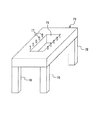
図2はこうした基礎架台の一構成例を表した斜視図である。
図2の基礎架台は、鉄筋コンクリート基礎75が脚部70により支持されてなる鉄筋コンクリートラーメン構造の高床式構造物である。鉄筋コンクリート基礎75は機械装置を据え付けるものであり、例えば機械装置として蒸気タービンを据え付ける場合、中央の開口76を介して下半側が階下に臨むように蒸気タービンを鉄筋コンクリート基礎75に支持させ、鉄筋コンクリート基礎75の下方に設置した復水器に連結する。蒸気タービンはそのケーシングに備えられたフランジが鉄筋コンクリート基礎75に植設されたアンカーボルト77によって鉄筋コンクリート基礎75に強固に固定される。
FIG. 2 is a perspective view showing an example of the structure of such a foundation frame.
2 is a stilt structure of a reinforced concrete ramen structure in which a reinforced
図2の例のように、機械装置を据え付ける鉄筋コンクリート基礎には、機械装置のフランジ等に設けられたボルト挿通用の穴のピッチに合わせて機械装置を固定するためのアンカーボルトを植設する必要がある。本発明はコンクリート基礎に対するこのアンカーボルトの設置構造に特徴を有するものである。鉄筋コンクリート基礎の形状は様々であり、上部に固定される機械装置の形状に合わせて設計される。図示したように、例えば発電用の大型タービン据付用基礎は架台形状であり、梁と柱から構成されたラーメン構造のコンクリート構造物とするのが一般的である。 As shown in the example of FIG. 2, it is necessary to plant anchor bolts for fixing the mechanical device in accordance with the pitch of the bolt insertion holes provided on the flange of the mechanical device, etc., on the reinforced concrete foundation on which the mechanical device is installed. There is. The present invention is characterized by the installation structure of the anchor bolt with respect to the concrete foundation. Reinforced concrete foundations have various shapes and are designed according to the shape of the mechanical device fixed to the top. As shown in the figure, for example, the foundation for installing a large turbine for power generation has a gantry shape, and is generally a concrete structure having a ramen structure composed of beams and columns.
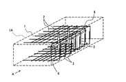
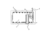
図3は本発明の一実施の形態に係る鉄筋コンクリート基礎の内部構成を表す部分斜視図、図4は図3中のA方向から見た透視図である。
図3及び図4に示すように、本発明の鉄筋コンクリート基礎は、主材となるコンクリート1、所要強度を発現させるためにコンクリート1内に配置した鉄筋2、鉄筋コンクリート基礎完成外形1A(点線で図示)から先端が突出するようにコンクリート1に植設され固定された機械装置据え付け用のアンカーボルト3、及びアンカーボルト3を挿通する穴を有しアンカーボルト3の固定位置を決めるテンプレート(受金具)4を備えている。
FIG. 3 is a partial perspective view showing the internal configuration of the reinforced concrete foundation according to the embodiment of the present invention, and FIG. 4 is a perspective view seen from the direction A in FIG.
As shown in FIGS. 3 and 4, the reinforced concrete foundation of the present invention includes a concrete 1 as a main material, a reinforcing bar 2 arranged in the concrete 1 to express a required strength, and a completed reinforced
鉄筋2には異形鉄筋が用いられることが通常であり構造計算に従って本数・径・間隔・配置形状が決められて鉄筋コンクリート基礎の躯体中に配筋される。通常、鉄筋2はコンクリート基礎の完成外形1Aの表面からかぶりと呼ばれる距離をおいた内側で格子状に配置されて籠状の形状をなす。
In general, deformed reinforcing bars are used for the reinforcing bars 2, and the number, diameter, interval and arrangement shape are determined according to the structural calculation, and the reinforcing bars are arranged in the frame of the reinforced concrete foundation. Usually, the reinforcing bars 2 are arranged in a lattice shape inside a distance called a fog from the surface of the finished
テンプレート4はテンプレート支柱5及びテンプレート梁6とともにアンカーボルト固定用の埋設型テンプレート架台を構成する。またテンプレート梁6は、鉄筋2とともに所要強度を発現させるための構造材をなすように前記鉄筋の配列に組み入れられており、テンプレート梁6を含めた構造が所要強度を有するように構成されている。つまり鉄筋2の一部に代えてテンプレート梁6を配することで、構造計算にテンプレート梁6を考慮可能としている。 The template 4 constitutes an embedded template frame for anchor bolt fixation together with the template support 5 and the template beam 6. The template beam 6 is incorporated in the reinforcing bar array so as to form a structural material for expressing the required strength together with the reinforcing bar 2, and the structure including the template beam 6 is configured to have the required strength. . That is, by providing the template beam 6 instead of a part of the reinforcing bar 2, the template beam 6 can be considered in the structural calculation.
テンプレート支柱5はテンプレート梁6及びテンプレート4を支持するものであってH型鋼等の鉄骨材料で構成され、例えば本基礎架台を設置するコンクリート基礎等に設定されたベースプレートに固定されたりコンクリート基礎に底部が埋め込まれたりして固定される。本基礎架台のコンクリート打設が数回に分けて行われる場合、アンカーボルトが埋め込まれるコンクリート打設の直前のコンクリート打設時にテンプレート支柱5の底部を埋め込むこともできる。こうして固定されたテンプレート支柱5にテンプレート梁6を溶接或いはボルト止めで所定の高さに固定する。テンプレート支柱5は先端部分が完成外形1Aの外側に突出しないように配置され、アンカーボルト固定用埋設型テンプレートの一部としてコンクリート基礎躯体中に全て埋設されるように設計されている。
The template support 5 supports the template beam 6 and the template 4 and is made of a steel material such as H-shaped steel. For example, the template support 5 is fixed to a base plate set on a concrete foundation or the like on which the foundation frame is installed, or is attached to the bottom of the concrete foundation. Is fixed by being embedded. When the concrete placement of the foundation frame is performed in several times, the bottom portion of the template column 5 can be buried at the time of concrete placement immediately before the concrete placement in which the anchor bolt is embedded. The template beam 6 is fixed to a predetermined height by welding or bolting to the template column 5 thus fixed. The template support 5 is arranged so that the tip portion does not protrude outside the finished
テンプレート梁6はH型鋼等の鉄骨材料で構成され、テンプレート支柱5に対して水平な姿勢で溶接又はボルト止めにより固定されている。またこのテンプレート梁6は溶接又はボルト止めによってテンプレート梁6に固定されたテンプレート4とともにアンカーボルト3を所定の位置に固定する。このテンプレート梁6は構造計算の考慮に入れられるように例えばH型鋼で構成された場合、H型鋼の上側ウェブ部分を構造部材とみなし、コンクリート基礎10の中立軸からの距離を中立軸と鉄筋2との距離とほぼ等距離となるように配置することで構造上の強度に寄与させたり、H型鋼全体の強度特性を構造計算に見込んだりして鉄筋2の一部に代える。いずれの強度計算の場合でも、テンプレート梁6はテンプレート支柱5とともにコンクリート基礎躯体中に完全に埋設されるように設計されている。
The template beam 6 is made of a steel material such as H-shaped steel, and is fixed to the template support 5 by welding or bolting in a horizontal posture. The template beam 6 fixes the
テンプレート4はL型鋼(山形鋼)等の形鋼で構成されており、テンプレート梁6に溶接又はボルト止めによりほぼ水平な姿勢で固定されている。もちろんH型鋼やI型鋼等といった他の形鋼を用いても良い。テンプレート4には、アンカーボルト3を設計通りの正確な位置に設定できるようにアンカーボルト3を通す穴が開けられている。このテンプレート4も鉄筋コンクリート基礎完成外形1Aの内側に位置するように鉄筋2とともにコンクリート1に埋設され、テンプレート梁6及びテンプレート支柱5とともに鉄筋コンクリート基礎の躯体中に埋め込まれる。
The template 4 is made of a shape steel such as an L-shaped steel (an angle steel), and is fixed to the template beam 6 in a substantially horizontal posture by welding or bolting. Of course, other shape steels such as H-shaped steel and I-shaped steel may be used. The template 4 has a hole through which the
アンカーボルト3はテンプレート4に開けられた穴に挿通され、これにより据え付ける機械装置側のボルト止めの位置に合った設計通りの位置に設定され、溶接やネジ止め等によってテンプレート4に固定される。こうした先行埋め込み型のアンカーボルト3は後に打設される基礎のコンクリートとの付着力によって固定される。アンカーボルト3の上部にはネジ山が切られており、機械装置にアンカーボルト3を通した状態でアンカーボルト3のネジ部にナットを締め付けることで、アンカーボルト3によって決められた位置に機械装置が固定される。鉄筋コンクリート基礎のコンクリートが打設終了後に硬化するまでには、気温やコンクリート特性等の条件によっても異なるが数日〜1週間以上の養生期間が必要である。
The
上記構成の鉄筋コンクリート基礎は以下の施工手順で構築される。
図3に示したような鉄筋コンクリート基礎を構築するには、まず鉄筋コンクリート基礎完成外形1Aの底面側から順に鉄筋2を配筋する。テンプレート支柱5は上端が鉄筋コンクリート基礎の躯体中に収まるように設計・加工されており、例えば底部が先行して埋め込まれて固定される。テンプレート支柱5を立てたら、このテンプレート支柱5に溶接やボルト止め等によってテンプレート梁6を水平に取り付け、さらにテンプレート梁6にテンプレート4をやはり溶接やボルト止め等により固定する。或いは予めテンプレート4をテンプレート梁6に取り付けておき、その後にテンプレート梁6をテンプレート支柱5に固定しても良い。このとき、テンプレート梁6は鉄筋コンクリート完成外形1Aからかぶりを置いて鉄筋2の配列に組み入れるようにして配置する。
The reinforced concrete foundation with the above configuration is constructed by the following construction procedure.
In order to construct a reinforced concrete foundation as shown in FIG. 3, first, reinforcing bars 2 are arranged in order from the bottom surface side of the completed reinforced
テンプレート4が固定されたら、次にアンカーボルト3を設定する。テンプレート4に開けた穴にアンカーボルト3を通し、上端のネジ部が鉄筋コンクリート基礎の完成外形1Aから突出する姿勢でアンカーボルト3を固定する。アンカーボルト3を固定したら、躯体内の底部を除く部分に配置する鉄筋2を配筋する。こうしてアンカーボルト3を固定したら、必要に応じてその他の基礎躯体中に埋設される電線管等を設定し、コンクリート1を打設する。コンクリート1の打設後はコンクリート1の強度発現のために数日〜1週間以上養生される。
After the template 4 is fixed, the
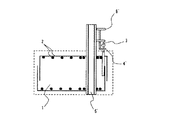
ここで、図5は一般的な鉄筋コンクリート基礎に用いられるテンプレート架台の構成を表す斜視図、図6は図5中のB方向から見た透視図である。
これら図5及び図6に示すように、一般的にテンプレート支柱5の上端は鉄筋コンクリート基礎外形1Aから突出しており、テンプレート支柱5の突出部分にテンプレート梁6’及びテンプレート4’が取り付けられる。そして、テンプレート4’に開けた穴を通してアンカーボルト3を懸垂して固定した状態でコンクリート1を打設し、コンクリート硬化後にコンクリート基礎完成外形より外部にあるテンプレート支柱5’を切断し、これに取り付けられたテンプレート梁6’・テンプレート4’とともに撤去することでアンカーボルト3をコンクリート基礎に設定している。
Here, FIG. 5 is a perspective view showing the configuration of a template mount used for a general reinforced concrete foundation, and FIG. 6 is a perspective view seen from the direction B in FIG.
As shown in FIGS. 5 and 6, the upper end of the template support 5 generally protrudes from the reinforced concrete foundation outline 1 </ b> A, and the template beam 6 ′ and the template 4 ′ are attached to the protruding portion of the template support 5. Then, the concrete 1 is placed with the
テンプレート梁6’には鉄骨が用いられ、テンプレート支柱5’に溶接又はボルト止めで取り付けられている。鉄骨の大きさや形状は、コンクリート1の打設時のコンクリートの流動力や硬化時の収縮力等の影響でアンカーボルト3が設計上の固定位置から移動して精度を失わないように決められている。構造鉄筋2については、基礎の構造計算により配筋形状・径・数量が決められている。しかし、構造鉄筋の配筋作業を行う際、アンカーボルト3・テンプレート4’・テンプレート支柱5’・テンプレート梁6’は施工後に撤去されるため構造計算時の配筋形状には考慮されない。また、鉄筋2の本数は構造計算により決まるため減らすことはできない。そのため、鉄筋2が他の部材の配置と重複する場合、アンカーボルトの配置が優先されるので鉄筋2はずらして配筋され、アンカーボルト3の配置を優先して鉄筋2をずらすことで局所的に鉄筋が密集する場所が生じがちである(図6等参照)。その結果、配筋或いはアンカーボルト3の設定の作業性が著しく低下したり、コンクリート打設時に部材の隙間が狭くなりコンクリートの充填が困難になったりする場合がある。
A steel frame is used for the template beam 6 'and is attached to the template support 5' by welding or bolting. The size and shape of the steel frame is determined so that the
さらに、テンプレートの撤去作業はコンクリート硬化後に開始されるため、コンクリート養生期間として数日〜1週間以上の間テンプレートを撤去することができず機械装置の据付作業日程が大きく制約される。 Furthermore, since the template removal work is started after the concrete is hardened, the template cannot be removed for several days to one week or more as a concrete curing period, and the installation work schedule of the mechanical device is greatly restricted.
それに対し、本実施の形態においては、アンカーボルト固定用のテンプレート架台が全て鉄筋コンクリート基礎躯体中に埋設されているため、テンプレート等の撤去作業を省略することができる。これによりコンクリート養生期間が経過したら直ちに機械装置の据え付けを実施することができ工期を大幅に短縮することができる。また、テンプレート架台が構造材を兼ねるため、テンプレート1等と鉄筋2との相対位置を図面上で容易に把握することができ、作業手順を考慮するのも容易である。 On the other hand, in this embodiment, since the template base for anchor bolt fixation is all embedded in the reinforced concrete foundation frame, the removal work of the template and the like can be omitted. As a result, the machine can be installed immediately after the concrete curing period elapses, and the construction period can be greatly shortened. Further, since the template mount also serves as a structural material, the relative position between the template 1 and the reinforcing bar 2 can be easily grasped on the drawing, and it is easy to consider the work procedure.
もちろん、アンカーボルト固定用のテンプレート架台が構造材を兼ねることで鉄筋2の物量を減少させることができ、テンプレート架台と鉄筋2との干渉も回避し易く鉄筋2の密集箇所を減少させることができる。したがって、鉄筋2の配筋作業やアンカーボルト固定用のテンプレート架台の設定作業の作業性が向上する。また鉄筋2の密集箇所が減少するので、コンクリート打設時にコンクリートを均一に充填し易い。 Of course, since the template base for fixing anchor bolts also serves as a structural material, the amount of the reinforcing bar 2 can be reduced, and interference between the template base and the reinforcing bar 2 can be easily avoided, and the density of the reinforcing bars 2 can be reduced. . Therefore, the workability of the reinforcing bar 2 and the setting work of the anchor base for fixing the anchor bolt is improved. Moreover, since the location where the rebar 2 is dense decreases, it is easy to uniformly fill the concrete when placing the concrete.
1 コンクリート
1A コンクリート基礎完成外形
2 鉄筋
3 アンカーボルト
4 テンプレート
5 テンプレート支柱
6 テンプレート梁
1
Claims (7)
主材となるコンクリートと、
所要強度を発現させるために前記コンクリート内に配置した鉄筋と、
完成外形から突出するように前記コンクリートに固定された機械装置据え付け用のアンカーボルトと、
このアンカーボルトを挿通する穴を有し前記アンカーボルトの固定位置を決めるものであって、完成外形の内側に位置するように前記鉄筋とともに前記コンクリートに埋設されたテンプレートと
を備えたことを特徴とする鉄筋コンクリート基礎。 In the reinforced concrete foundation where the machinery is installed,
Concrete as the main material,
Rebars arranged in the concrete to develop the required strength;
Anchor bolts for installing the mechanical device fixed to the concrete so as to protrude from the finished outer shape,
It has a hole through which the anchor bolt is inserted, and determines the fixing position of the anchor bolt, and includes a template embedded in the concrete together with the reinforcing bar so as to be positioned inside a completed outer shape. Reinforced concrete foundation.
主材となるコンクリートと、
所要強度を発現させるために前記コンクリート内に配置した鉄筋と、
完成外形から突出するように前記コンクリートに固定された機械装置据え付け用のアンカーボルトと、
このアンカーボルトを挿通する穴を有し前記アンカーボルトの固定位置を決めるものであって、完成外形の内側に位置するように前記鉄筋とともに前記コンクリートに埋設されたテンプレートと、
このテンプレートを支持するものであって、先端部分が完成外形の外側に突出しないように前記コンクリートに埋設された支柱と
を備えたことを特徴とする鉄筋コンクリート基礎。 In the reinforced concrete foundation where the machinery is installed,
Concrete as the main material,
Rebars arranged in the concrete to develop the required strength;
Anchor bolts for installing the mechanical device fixed to the concrete so as to protrude from the finished outer shape,
It has a hole through which this anchor bolt is inserted, determines the fixing position of the anchor bolt, and is a template embedded in the concrete together with the reinforcing bar so as to be positioned inside the completed outer shape,
A reinforced concrete foundation, which supports the template, and includes a column embedded in the concrete so that a tip portion does not protrude outside a completed outer shape.
前記アンカーボルトを挿通する穴を有し前記アンカーボルトの固定位置を決めるものであって、前記鉄筋コンクリート基礎の完成外形の内側に位置するように前記鉄筋とともに配設されたテンプレートを備えたことを特徴とするテンプレート架台。 In a template base used to install anchor bolts for installing a mechanical device at a required position on a reinforced concrete foundation having concrete as a main material and reinforcing bars arranged in the concrete to express the required strength,
It has a hole for inserting the anchor bolt and determines a fixing position of the anchor bolt, and includes a template disposed with the reinforcing bar so as to be positioned inside a completed outer shape of the reinforced concrete foundation. A template mount.
完成外形の内側に位置するようにテンプレートを配設し、
前記テンプレートに開けられた穴に機械装置据え付け用のアンカーボルトを挿通してこのアンカーボルトの固定位置を決め、
コンクリートを打設して鉄筋とともに前記テンプレートをコンクリートに埋設し、コンクリートを打設した時点で前記アンカーボルトのみが完成外形の外部に突出した状態に構成する
ことを特徴とする鉄筋コンクリート基礎の構築方法。 In the construction method of the reinforced concrete foundation to install the mechanical device,
Arrange the template so that it is located inside the completed outline,
Insert anchor bolts for machine installation into the holes opened in the template to determine the fixing position of the anchor bolts,
A method for constructing a reinforced concrete foundation, wherein concrete is cast and the template is embedded in the concrete together with a reinforcing bar, and only the anchor bolt protrudes outside the finished outer shape when the concrete is placed.
Priority Applications (1)
| Application Number | Priority Date | Filing Date | Title |
|---|---|---|---|
| JP2005180418A JP2007002425A (en) | 2005-06-21 | 2005-06-21 | Reinforced concrete foundation, template mount and method for constructing reinforced concrete foundation |
Applications Claiming Priority (1)
| Application Number | Priority Date | Filing Date | Title |
|---|---|---|---|
| JP2005180418A JP2007002425A (en) | 2005-06-21 | 2005-06-21 | Reinforced concrete foundation, template mount and method for constructing reinforced concrete foundation |
Publications (1)
| Publication Number | Publication Date |
|---|---|
| JP2007002425A true JP2007002425A (en) | 2007-01-11 |
Family
ID=37688287
Family Applications (1)
| Application Number | Title | Priority Date | Filing Date |
|---|---|---|---|
| JP2005180418A Pending JP2007002425A (en) | 2005-06-21 | 2005-06-21 | Reinforced concrete foundation, template mount and method for constructing reinforced concrete foundation |
Country Status (1)
| Country | Link |
|---|---|
| JP (1) | JP2007002425A (en) |
Cited By (9)
| Publication number | Priority date | Publication date | Assignee | Title |
|---|---|---|---|---|
| JP2011043007A (en) * | 2009-08-24 | 2011-03-03 | Hitachi Ltd | Footing stand |
| CN103938649A (en) * | 2014-03-26 | 2014-07-23 | 中建四局第六建筑工程有限公司 | Method for constructing cavity foundation of super high-rise building |
| CN104674832A (en) * | 2014-12-26 | 2015-06-03 | 枣庄矿业集团高庄煤业有限公司 | Construction method of foundation frame |
| CN105821901A (en) * | 2016-04-07 | 2016-08-03 | 陈文博 | Blast furnace body foundation engineering construction process |
| CN105887920A (en) * | 2016-04-30 | 2016-08-24 | 国家电网公司 | Construction method for leveling top plate type master variable foundation through cross beam |
| CN105926662A (en) * | 2016-04-30 | 2016-09-07 | 国家电网公司 | Construction method of top plate type main transformer foundation |
| CN109162251A (en) * | 2018-10-25 | 2019-01-08 | 南通铁军机械有限公司 | Navigation channel wall-body shore protection external entirety vibrational moving mould device |
| CN114319120A (en) * | 2021-12-29 | 2022-04-12 | 中交武汉港湾工程设计研究院有限公司 | Intelligent template system and method |
| CN114622590A (en) * | 2022-03-18 | 2022-06-14 | 中铁广州工程局集团深圳工程有限公司 | High-steep slope circular pier column in-situ single-pile upper tower crane foundation structure and construction method |
-
2005
- 2005-06-21 JP JP2005180418A patent/JP2007002425A/en active Pending
Cited By (12)
| Publication number | Priority date | Publication date | Assignee | Title |
|---|---|---|---|---|
| JP2011043007A (en) * | 2009-08-24 | 2011-03-03 | Hitachi Ltd | Footing stand |
| CN103938649A (en) * | 2014-03-26 | 2014-07-23 | 中建四局第六建筑工程有限公司 | Method for constructing cavity foundation of super high-rise building |
| CN104674832A (en) * | 2014-12-26 | 2015-06-03 | 枣庄矿业集团高庄煤业有限公司 | Construction method of foundation frame |
| CN105821901A (en) * | 2016-04-07 | 2016-08-03 | 陈文博 | Blast furnace body foundation engineering construction process |
| CN105887920A (en) * | 2016-04-30 | 2016-08-24 | 国家电网公司 | Construction method for leveling top plate type master variable foundation through cross beam |
| CN105926662A (en) * | 2016-04-30 | 2016-09-07 | 国家电网公司 | Construction method of top plate type main transformer foundation |
| CN105926662B (en) * | 2016-04-30 | 2017-10-13 | 国家电网公司 | A kind of construction method of top plate type main transformer foundation |
| CN105887920B (en) * | 2016-04-30 | 2018-01-05 | 国家电网公司 | A kind of construction method of top plate type main transformer foundation using crossbeam smoothing |
| CN109162251A (en) * | 2018-10-25 | 2019-01-08 | 南通铁军机械有限公司 | Navigation channel wall-body shore protection external entirety vibrational moving mould device |
| CN114319120A (en) * | 2021-12-29 | 2022-04-12 | 中交武汉港湾工程设计研究院有限公司 | Intelligent template system and method |
| CN114319120B (en) * | 2021-12-29 | 2024-04-16 | 中交武汉港湾工程设计研究院有限公司 | Intelligent template system and method |
| CN114622590A (en) * | 2022-03-18 | 2022-06-14 | 中铁广州工程局集团深圳工程有限公司 | High-steep slope circular pier column in-situ single-pile upper tower crane foundation structure and construction method |
Similar Documents
| Publication | Publication Date | Title |
|---|---|---|
| CN101813069B (en) | Foundation for enabling anchoring of wind turbine tower thereto by means of replaceable through-bolts | |
| JP5189571B2 (en) | Foundation stand | |
| JP6316948B2 (en) | Wind power generator base | |
| KR102205960B1 (en) | Tower connection structure of foundation structure for partial repowering of new wind turbine, and construction method for the same | |
| JP2015501891A (en) | Wind power generator basics | |
| KR101186053B1 (en) | Method of Constructing Insitu Concrete Beam Using Preinstalled Precast Concrete Slab | |
| JP2013148064A (en) | Support structure of steam turbine bearing and steam turbine | |
| KR200483763Y1 (en) | Reinforced structure of a wind turbine foundation structures | |
| US9726045B2 (en) | Turbine external compartment, frame for turbine external compartment, and method of constructing frame for turbine external compartment | |
| JP6057579B2 (en) | Seismic isolation device support structure and construction method of seismic isolation device support structure | |
| JPH10311049A (en) | Work executing method for turbine frame of steel plate concrete and locating jig for burying metal piece | |
| JP4416141B2 (en) | How to install seismic isolation devices | |
| JP2009299419A (en) | Construction method for preventing displacement of form, and installment tool | |
| JPH09125415A (en) | Base stand for equipment | |
| JP4358408B2 (en) | Power generation facility mount and method for manufacturing power generation facility mount | |
| JP2004316278A (en) | Structure of steel pipe plinth part | |
| JP6596267B2 (en) | Equipment installation stand, manufacturing method thereof, and plant | |
| JP6596268B2 (en) | Equipment installation stand, manufacturing method thereof, and plant | |
| JP2012215038A (en) | Joint structure for steel plate concrete structure | |
| JP2007262798A (en) | Installation method and installation structure of power generation equipment | |
| JP2005207130A (en) | Equipment stand | |
| JPS62328B2 (en) | ||
| JP3601999B2 (en) | Construction method of reactor containment vessel and its diaphragm floor | |
| JP2652410B2 (en) | Assembling method of mounting frame for air conditioning means | |
| JP2011099211A (en) | Post-driven anchor structure of steel plate concrete structure, and method for post-driving anchor for the steel plate concrete structure |