JP2007011237A - Imaging lens - Google Patents
Imaging lens Download PDFInfo
- Publication number
- JP2007011237A JP2007011237A JP2005195545A JP2005195545A JP2007011237A JP 2007011237 A JP2007011237 A JP 2007011237A JP 2005195545 A JP2005195545 A JP 2005195545A JP 2005195545 A JP2005195545 A JP 2005195545A JP 2007011237 A JP2007011237 A JP 2007011237A
- Authority
- JP
- Japan
- Prior art keywords
- lens
- object side
- imaging
- imaging lens
- linear expansion
- Prior art date
- Legal status (The legal status is an assumption and is not a legal conclusion. Google has not performed a legal analysis and makes no representation as to the accuracy of the status listed.)
- Granted
Links
- 238000003384 imaging method Methods 0.000 title claims abstract description 70
- 230000005499 meniscus Effects 0.000 claims abstract description 10
- 230000003287 optical effect Effects 0.000 claims abstract description 9
- 230000014509 gene expression Effects 0.000 claims description 20
- 239000000463 material Substances 0.000 claims description 14
- 239000004033 plastic Substances 0.000 claims description 14
- 229920003023 plastic Polymers 0.000 claims description 14
- 239000011521 glass Substances 0.000 claims description 9
- 230000004075 alteration Effects 0.000 abstract description 40
- 238000010586 diagram Methods 0.000 description 15
- 201000009310 astigmatism Diseases 0.000 description 9
- 230000000694 effects Effects 0.000 description 5
- 239000006059 cover glass Substances 0.000 description 2
- 239000006185 dispersion Substances 0.000 description 2
- 230000002411 adverse Effects 0.000 description 1
- 238000004519 manufacturing process Methods 0.000 description 1
Images
Classifications
-
- G—PHYSICS
- G02—OPTICS
- G02B—OPTICAL ELEMENTS, SYSTEMS OR APPARATUS
- G02B13/00—Optical objectives specially designed for the purposes specified below
- G02B13/001—Miniaturised objectives for electronic devices, e.g. portable telephones, webcams, PDAs, small digital cameras
- G02B13/0015—Miniaturised objectives for electronic devices, e.g. portable telephones, webcams, PDAs, small digital cameras characterised by the lens design
- G02B13/002—Miniaturised objectives for electronic devices, e.g. portable telephones, webcams, PDAs, small digital cameras characterised by the lens design having at least one aspherical surface
- G02B13/004—Miniaturised objectives for electronic devices, e.g. portable telephones, webcams, PDAs, small digital cameras characterised by the lens design having at least one aspherical surface having four lenses
-
- G—PHYSICS
- G02—OPTICS
- G02B—OPTICAL ELEMENTS, SYSTEMS OR APPARATUS
- G02B13/00—Optical objectives specially designed for the purposes specified below
- G02B13/18—Optical objectives specially designed for the purposes specified below with lenses having one or more non-spherical faces, e.g. for reducing geometrical aberration
-
- G—PHYSICS
- G02—OPTICS
- G02B—OPTICAL ELEMENTS, SYSTEMS OR APPARATUS
- G02B9/00—Optical objectives characterised both by the number of the components and their arrangements according to their sign, i.e. + or -
- G02B9/34—Optical objectives characterised both by the number of the components and their arrangements according to their sign, i.e. + or - having four components only
Landscapes
- Physics & Mathematics (AREA)
- General Physics & Mathematics (AREA)
- Optics & Photonics (AREA)
- Lenses (AREA)
- Window Of Vehicle (AREA)
- Glass Compositions (AREA)
Abstract
Description
本発明は、比較的少ないレンズ枚数で構成されたコンパクトな撮像レンズに関し、特に、PCや携帯端末などの画像取込用のレンズに好適な撮像レンズに関するものである。 The present invention relates to a compact imaging lens having a relatively small number of lenses, and more particularly to an imaging lens suitable for a lens for capturing an image such as a PC or a portable terminal.
従来より、比較的薄型のPC用Webカメラ、携帯端末等に使用されている画像取り込み用レンズモジュールとして、3枚のプラスチックレンズを配列した構成のものが知られている。 2. Description of the Related Art Conventionally, as an image capturing lens module used in a relatively thin PC web camera, portable terminal, etc., a configuration in which three plastic lenses are arranged is known.
例えば、下記特許文献1に開示されている撮像レンズにおいては、3枚のレンズ構成でありながらレンズ系の全長は短く構成され、さらに最も像側に所定形状の両面非球面レンズを配することによって撮像面全面に対する主光線の入射角を小さくし、撮像素子の適用を可能とするように構成されている。なお、従前はこの種の分野において単レンズ構成の撮像レンズが用いられていたが、特許文献1記載の技術によって撮像素子の高解像化、拡大化といった要請に応えることが可能となった。
For example, in the imaging lens disclosed in the following
しかし、3枚のレンズ全てをプラスチックレンズにした場合、使用時の温度変化に伴いピント位置にばらつきが出ていた。このような問題を克服するためにオートフォーカスの機能を採用することが考えられるが、上記薄型の機器(携帯端末等)にオートフォーカスの機能を採用することは困難である。これは、レンズモジュールのスペース増大、構造的強度の低下、カメラとしての機動性の低下、製造コストの増大といった問題が生じるためである。また、温度変化によるピント位置のばらつきは、3枚のレンズ全てをガラスにすることで解決されるが、コストが増大し好ましくない。 However, when all the three lenses were made of plastic lenses, the focus position varied with temperature changes during use. In order to overcome such a problem, it is conceivable to adopt an autofocus function, but it is difficult to adopt the autofocus function for the above-described thin device (such as a portable terminal). This is because problems such as an increase in the space of the lens module, a decrease in structural strength, a decrease in mobility as a camera, and an increase in manufacturing cost occur. Further, the variation in focus position due to temperature change can be solved by making all three lenses glass, but this is not preferable because the cost increases.
本発明は上記事情に鑑みなされたものであり、色収差を始めとする諸収差の補正を良好なものとしつつ、温度変化に伴うピント位置の変動を抑制し、かつレンズ全長をコンパクトなものとし得るパンフォーカスに着目した撮像レンズを提供することを目的とするものである。 The present invention has been made in view of the above circumstances, and can correct the various aberrations including the chromatic aberration, suppress the fluctuation of the focus position due to the temperature change, and can make the total lens length compact. An object of the present invention is to provide an imaging lens that focuses on pan focus.
本発明の第1の撮像レンズは、物体側より順に正レンズからなる第1レンズ、像側に凹面を向けた負レンズからなる第2レンズ、物体側に凹面を向けた両面非球面の正レンズからなる第3レンズ、両面非球面の光軸近傍で物体側に凸のメニスカスレンズからなる第4レンズを配列してなり、以下の条件式(1)〜(6)を満足することを特徴とするものである。 The first imaging lens of the present invention includes a first lens composed of a positive lens in order from the object side, a second lens composed of a negative lens having a concave surface facing the image side, and a double-sided aspherical positive lens facing the concave surface facing the object side. And a fourth lens composed of a meniscus lens convex on the object side in the vicinity of the optical axis of the double-sided aspheric surface, and satisfying the following conditional expressions (1) to (6): To do.
0.3<|f1/ f2|<0.8 (1)
νdG1−νdG2>25 (2)
|A1|<1.5×10⁻⁵ (3)
|A2|<1.5×10⁻⁵ (4)
|A3|>1.5×10⁻⁵ (5)
|A4|>1.5×10⁻⁵ (6)
f1:前記第1レンズの焦点距離
f2:前記第2レンズの焦点距離
νdG1:前記第1レンズのアッベ数
νdG2:前記第2レンズのアッベ数
A1:前記第1レンズの線膨張係数
A2:前記第2レンズの線膨張係数
A3:前記第3レンズの線膨張係数
A4:前記第4レンズの線膨張係数
0.3 <| f 1 / f 2 | <0.8 (1)
ν dG1 −ν dG2 > 25 (2)
| A1 | <1.5 × 10 -5 (3)
| A2 | <1.5 × 10 -5 (4)
| A3 | > 1.5 × 10 -5 (5)
| A4 | > 1.5 × 10 -5 (6)
f 1 : Focal length of the first lens
f 2 : focal length of the second lens ν dG1 : Abbe number of the first lens ν dG2 : Abbe number of the second lens
A1: Linear expansion coefficient of the first lens
A2: Linear expansion coefficient of the second lens
A3: Linear expansion coefficient of the third lens
A4: Linear expansion coefficient of the fourth lens
また、本発明の第2の撮像レンズは、物体側より順に、ガラス材料により形成された正レンズからなる第1レンズ、像側に凹面を向けたガラス材料により形成された負レンズからなる第2レンズ、物体側に凹面を向けた両面非球面のプラスチック材料により形成された正レンズからなる第3レンズ、両面非球面のプラスチック材料により形成された光軸近傍で物体側に凸のメニスカスレンズからなる第4レンズを配列してなり、以下の条件式(1)および(2)を満足することを特徴とするものである。 In addition, the second imaging lens of the present invention includes, in order from the object side, a first lens made of a positive lens made of a glass material, and a second lens made of a glass material having a concave surface facing the image side. A lens, a third lens composed of a positive lens made of a double-sided aspheric plastic material with the concave surface facing the object side, and a meniscus lens convex to the object side near the optical axis formed of a double-sided aspheric plastic material The fourth lens is arranged, and satisfies the following conditional expressions (1) and (2).
0.3<|f1/ f2|<0.8 (1)
νdG1−νdG2>25 (2)
f1:前記第1レンズの焦点距離
f2:前記第2レンズの焦点距離
νdG1:前記第1レンズのアッベ数
νdG2:前記第2レンズのアッベ数
0.3 <| f 1 / f 2 | <0.8 (1)
ν dG1 −ν dG2 > 25 (2)
f 1 : Focal length of the first lens
f 2 : focal length of the second lens ν dG1 : Abbe number of the first lens ν dG2 : Abbe number of the second lens
また、上記第1レンズおよび上記第2レンズの両面は各々球面とされていることが好ましい。ただし、ここでいう「球面」は平面をも含むものとする。 Moreover, it is preferable that both surfaces of the first lens and the second lens are spherical surfaces. However, the “spherical surface” mentioned here includes a plane.
また、上記非球面レンズにおける正、負は光軸付近での屈折力を表すものとする。 Further, positive and negative in the aspheric lens represent refractive power near the optical axis.
本発明の第1の撮像レンズにおいては、第1レンズの焦点距離と第2レンズの焦点距離の比を条件式(1)の範囲内に収めることにより、レンズ系の全長を短くできるようになっている。また、第1レンズと第2レンズのアッベ数の差は、条件式(2)において25を上回るようになっており、この条件を満足することにより良好な色収差補正を行うことができる。また、物体側の2枚のレンズを条件式(3)、(4)で示されるような比較的線膨張係数の小さい材料によって形成することにより、温度変化に対応し得るピント移動の少ないレンズ系とすることが可能となる。つまり、レンズ系全長は短いままでありながら、良好な温度特性を備えたパンフォーカスレンズとして構成することが可能となる。 In the first imaging lens of the present invention, the total length of the lens system can be shortened by keeping the ratio of the focal length of the first lens and the focal length of the second lens within the range of conditional expression (1). ing. Further, the difference in Abbe number between the first lens and the second lens exceeds 25 in the conditional expression (2), and satisfactory chromatic aberration correction can be performed by satisfying this condition. In addition, by forming the two lenses on the object side with a material having a relatively small linear expansion coefficient as shown in the conditional expressions (3) and (4), a lens system with less focus movement that can cope with temperature changes. It becomes possible. That is, it is possible to configure as a pan focus lens having good temperature characteristics while the entire length of the lens system remains short.
一方、本発明の第2の撮像レンズにおいては、ガラスにより形成された第1レンズと第2レンズを用い、プラスチックにより形成された第3レンズと第4レンズを用いるとともに、条件式(1)、(2)を満足することにより、上記第1の撮像レンズと同等の効果を奏することができるようになっている。 On the other hand, in the second imaging lens of the present invention, the first lens and the second lens made of glass are used, the third lens and the fourth lens made of plastic are used, and conditional expression (1), By satisfying (2), an effect equivalent to that of the first imaging lens can be obtained.
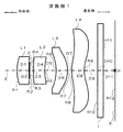
以下、本発明の具体的な実施形態について図面を参照しつつ説明する。図1に示す実施形態(実施例1のものを代表させて示している)の撮像レンズは、物体側より順に、正レンズからなる第1レンズL1、像側に凹面を向けた負レンズからなる第2レンズL2、物体側に凹面を向けた両面非球面の正のメニスカスレンズからなる第3レンズL3、両面非球面の負レンズからなる第4レンズL4を配列してなり、光軸Xに沿って入射する光束を撮像素子(撮像面)3の結像位置Pに効率良く収束させるようにした撮像レンズである。また、第1レンズL1の像側には絞り2が配され、第4レンズL4と撮像素子3との間にはカバーガラス1が配されている。
Hereinafter, specific embodiments of the present invention will be described with reference to the drawings. The imaging lens of the embodiment shown in FIG. 1 (representing the lens of Example 1 as a representative) includes, in order from the object side, a first lens L 1 made of a positive lens and a negative lens with a concave surface facing the image side. A second lens L 2 , a third lens L 3 composed of a double-sided aspheric positive meniscus lens with a concave surface facing the object side, and a fourth lens L 4 composed of a double-sided aspheric negative lens. This is an imaging lens that efficiently converges a light beam incident along the axis X to an imaging position P of the imaging element (imaging surface) 3. A
なお、各レンズ面の非球面形状は、下記非球面式で表される。 The aspheric shape of each lens surface is represented by the following aspheric expression.
また、本実施形態の撮像レンズは、以下の条件式(1)〜(6)を満足している。
0.3<|f1/ f2|<0.8 (1)
νdG1−νdG2>25 (2)
|A1|<1.5×10⁻⁵ (3)
|A2|<1.5×10⁻⁵ (4)
|A3|>1.5×10⁻⁵ (5)
|A4|>1.5×10⁻⁵ (6)
ただし、
f1:前記第1レンズの焦点距離
f2:前記第2レンズの焦点距離
νdG1:前記第1レンズのアッベ数
νdG2:前記第2レンズのアッベ数
A1:前記第1レンズの線膨張係数
A2:前記第2レンズの線膨張係数
A3:前記第3レンズの線膨張係数
A4:前記第4レンズの線膨張係数
In addition, the imaging lens of the present embodiment satisfies the following conditional expressions (1) to (6).
0.3 <| f 1 / f 2 | <0.8 (1)
ν dG1 −ν dG2 > 25 (2)
| A1 | <1.5 × 10 -5 (3)
| A2 | <1.5 × 10 -5 (4)
| A3 | > 1.5 × 10 -5 (5)
| A4 | > 1.5 × 10 -5 (6)
However,
f 1 : Focal length of the first lens
f 2 : focal length of the second lens ν dG1 : Abbe number of the first lens ν dG2 : Abbe number of the second lens
A1: Linear expansion coefficient of the first lens
A2: Linear expansion coefficient of the second lens
A3: Linear expansion coefficient of the third lens
A4: Linear expansion coefficient of the fourth lens
次に本実施形態による作用効果を説明する。
本実施形態の撮像レンズによれば、主に第1レンズL1および第2レンズL2が光収束機能と色収差の補正機能を有し、第3レンズL3および第4レンズL4が球面収差等の他の収差補正機能を有したものとなっている。
Next, the function and effect of this embodiment will be described.
According to the imaging lens of the present embodiment, the first lens L 1 and the second lens L 2 mainly have a light convergence function and a chromatic aberration correction function, and the third lens L 3 and the fourth lens L 4 have spherical aberration. And other aberration correction functions.
本実施形態の撮像レンズにおいては、第1レンズL1の焦点距離f1と第2レンズL2の焦点距離f2の比を条件式(1)の範囲内に収めることにより、レンズ系の全長を短くできるようになっている。また、第1レンズL1と第2レンズL2のアッベ数の差は、条件式(2)から25を上回るようになっており、この条件を満足することにより良好な色収差補正を行うことができる。また、上記特許文献1に示すような3枚のプラスチックレンズにおいて、物体側の第1レンズL1のみを条件式(3)、(4)で示されるような比較的線膨張係数の小さい材料よりなる2枚のレンズに変えることにより、温度変化に対応し得るピント移動の少ないレンズ系とすることが可能となる。すなわち、本実施形態の撮像レンズでは、レンズ系全長は短いままでありながら、良好な温度特性を備えたパンフォーカスレンズとして構成することが可能となる。
In the imaging lens of the present embodiment, by keeping the ratio of the focal length f 2 of the focal length f 1 and the second lens L 2 of the first lens L 1 in the range of the conditional expression (1), the total length of the lens system Can be shortened. The first lens L 1 and the difference in the Abbe number of the second lens L 2, which consists of the conditional expression (2) to exceed 25, becomes possible to excellently correct chromatic aberration by satisfying this condition it can. Also, in three of the plastic lens as shown in
一方、本実施形態の撮像レンズにおいては、ガラスにより形成された第1レンズL1と第2レンズL2を用い、プラスチックにより形成された第3レンズL3と第4レンズL4を用いることにより、物体側の2つのレンズを線膨張係数の低いものとしつつ、全てのレンズをガラスレンズで作成することの弊害を排除することができる。すなわち、温度変化に対してピント位置の変動に大きな影響を与えるレンズ材料の特性としては屈折率と線膨張係数があるが、レンズ材料としてプラスチックを用いると、一般にプラスチック材料では温度の上昇に応じて屈折率が大幅に低下するとともに、線膨張係数(体膨張係数)は大幅に増加するため、いずれもピント位置までの距離を大きくするように作用する。そこで、物体側に位置するとともに光収束機能を主に担っている、第1レンズL1と第2レンズL2を、屈折率および線膨張係数の温度変化が小さいガラス材料により形成することにより、ピント位置の変動を大幅に低減するようにしている。 On the other hand, in the imaging lens of the present embodiment, using the first lens L 1 and second lens L 2 formed of glass, by using a third lens L 3 which is formed by a plastic fourth lens L 4 The adverse effect of making all the lenses with glass lenses can be eliminated while making the two lenses on the object side have a low linear expansion coefficient. In other words, the characteristics of lens materials that have a large effect on fluctuations in focus position with respect to temperature changes include refractive index and linear expansion coefficient. When plastics are used as lens materials, plastic materials generally respond to temperature increases. While the refractive index is significantly reduced and the linear expansion coefficient (body expansion coefficient) is significantly increased, both act to increase the distance to the focus position. Therefore, plays mainly the light convergence function while positioned on the object side, by a first lens L 1 and second lens L 2, is formed by a temperature change is small glass material refractive index and the linear expansion coefficient, The focus position fluctuation is greatly reduced.
このことに加え、条件式(1)、(2)を満足することにより、レンズ系の全長と色収差補正に関し、上記第1の撮像レンズと同等の効果を奏することができるようになっている。 In addition to this, by satisfying conditional expressions (1) and (2), the same effect as the first imaging lens can be achieved with respect to the overall length of the lens system and chromatic aberration correction.
以下、上述した各条件式(1)〜(6)についての技術的意義を説明する。
上記条件式(1)は、第1レンズL1と第2レンズL2の焦点距離の比を0.3〜0.8に収めることを規定したものであり、これによりレンズ系の全長を短くすることが可能となる。すなわち、この上限を上回ると第1レンズL1と第2レンズL2の合成パワーが小さくなり、レンズ系の全長は長くなる。一方、下限を下回ると十分な色収差補正が困難となる。
The technical significance of the conditional expressions (1) to (6) described above will be described below.
Condition (1) is obtained by defining that fit the first lens L 1 and the ratio of the second focal length of the lens L 2 to 0.3 and 0.8, can thereby shorten the overall length of the lens system It becomes. That is, when the value exceeds the upper limit first lens L 1 and the second combined power of the lens L 2 is reduced, the overall length of the lens system becomes long. On the other hand, below the lower limit, it becomes difficult to sufficiently correct chromatic aberration.
上記条件式(2)は、第1レンズL1のアッベ数と第2レンズL2のアッベ数の差が25を上回ることを規定したものであり、第1レンズL1を低分散、第2レンズL2を高分散なレンズとすることにより、色収差補正を良好なものとすることができる。つまり、下限を下回ると、緑色域光に対して赤色域光が過度にオーバーになるとともに、緑色域光に対して青色域光が過度にアンダーになり、十分な色収差補正が困難となる。 Condition (2) is for the difference between the Abbe numbers of the first lens L 1 and the Abbe number of the second lens L 2 is defined to be greater than 25, low dispersion of the first lens L 1, second the lens L 2 by a high-dispersion lens makes it possible to correct chromatic aberration good. That is, below the lower limit, the red range light is excessively over the green range light, and the blue range light is excessively under the green range light, making it difficult to sufficiently correct chromatic aberration.
上記条件式(3)〜(6)は、第1レンズL1と第2レンズL2の線膨張係数の上限(該条件式(3)、(4))および、第3レンズL3と第4レンズL4の線膨張係数の下限(該条件式(5)、(6))を規定したものである。特に、上式(3)、(4)の上限を上回るとピント移動が大きくなり、レンズ系として十分に機能しなくなる。 The conditional expressions (3) to (6) are the upper limits of the linear expansion coefficients of the first lens L 1 and the second lens L 2 (the conditional expressions (3) and (4)) and the third lens L 3 and the second lens L 3 . the lower limit of the fourth lens linear expansion coefficient of the L 4 (the conditional expression (5), (6)) is obtained by defining. In particular, if the upper limit of the above formulas (3) and (4) is exceeded, the focus movement becomes large and the lens system does not function sufficiently.
以下、具体的な実施例を用いて、本発明の撮像レンズをさらに説明する。
なお、以下の各実施例に示す数値は、全系の焦点距離を1.0mmとして規格化された値となっている。
Hereinafter, the imaging lens of the present invention will be further described using specific examples.
In addition, the numerical value shown to each following Example is the value normalized by making the focal distance of the whole system into 1.0 mm.
<実施例1>
実施例1に係る撮像レンズの概略構成を図1に示す。この撮像レンズは、物体側より順に、物体側に強い曲率の面を向けた正のメニスカスレンズからなる第1レンズL1、絞り2、物体側に弱い曲率の面を向けた負のメニスカスレンズからなる第2レンズL2、物体側に凹面を向けた両面非球面の正のメニスカスレンズからなる第3レンズL3および両面非球面の負レンズからなる第4レンズL4を配列している。なお、第4レンズL4は物体側の面において、光軸近傍で正、周辺で負の曲率を有するように構成されており、また像側の面においても曲率が変化する割合は違うものの、略同様の曲率符号の変化となるように構成されている。また、本実施例および下述する実施例2の撮像レンズのように絞り2を第1レンズL1と第2レンズL2の間に配した中絞りの構成とすることにより、像面湾曲をより良好に補正することができる。
<Example 1>
FIG. 1 shows a schematic configuration of the imaging lens according to the first embodiment. The imaging lens includes, in order from the object side, a first lens L 1 composed of a positive meniscus lens having a strong curvature surface facing the object side, an
この撮像レンズの各レンズ面の曲率半径R(mm)、各レンズの中心厚および各レンズ間の空気間隔(以下、これらを総称して軸上面間隔という)D(mm)、各レンズのd線における、屈折率Nおよびアッベ数νの値を表1に示す。なお表中の数字は、物体側からの順番を表すものである(第3面は絞り面、第12面は撮像面)。また、表2には、各非球面について、上記非球面式に示される非球面の各定数K、B3、B4、B5、B6、B7、B8、B9、B10の値を示す。 The radius of curvature R (mm) of each lens surface of this imaging lens, the center thickness of each lens and the air space between each lens (hereinafter collectively referred to as the axial upper surface distance) D (mm), the d line of each lens Table 1 shows values of the refractive index N and the Abbe number ν. The numbers in the table represent the order from the object side (the third surface is the aperture surface, and the twelfth surface is the imaging surface). In Table 2, for each aspheric surface, the constants K, B 3 , B 4 , B 5 , B 6 , B 7 , B 8 , B 9 , B 10 of the aspheric surface shown in the above aspheric formula are shown. Indicates the value.
また、実施例1の撮像レンズによれば、表7に示すように、条件式(1)〜(6)は全て満足されている。また、レンズ系の全長は1.28mmとされている。 Moreover, according to the imaging lens of Example 1, as shown in Table 7, all the conditional expressions (1) to (6) are satisfied. The total length of the lens system is 1.28 mm.
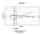
図2は実施例1の撮像レンズの温度変化に対応するピント位置のずれを示すものである。従前のプラスチックレンズ(例えば上述した特許文献1に示すレンズ;以下同じ)では−20〜60℃の温度変化に対して略±0.05mmのピント位置のずれであったものが、本実施例では該温度変化において±0.01mm以内と良好なものとなっている。
FIG. 2 shows the shift of the focus position corresponding to the temperature change of the imaging lens of the first embodiment. In a conventional plastic lens (for example, the lens shown in
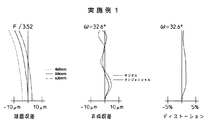
図3は実施例1の撮像レンズの球面収差、非点収差、およびディストーションを示す収差図である。なお、非点収差図には、サジタル像面およびタンジェンシャル像面に対する収差が示されている。これらの収差図においてωは半画角を示す。これらの収差図から明らかなように、実施例1の撮像レンズによれば、各収差を良好に補正することができる。 3 is an aberration diagram illustrating spherical aberration, astigmatism, and distortion of the imaging lens of Example 1. FIG. In the astigmatism diagram, aberrations with respect to the sagittal image surface and the tangential image surface are shown. In these aberration diagrams, ω represents a half angle of view. As is apparent from these aberration diagrams, according to the imaging lens of Example 1, each aberration can be corrected satisfactorily.
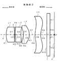
<実施例2>
実施例2に係る撮像レンズの概略構成を図4に示す。この撮像レンズの構成も実施例1のものと略同様であり、対応する図面の説明において同一の要素については同一の符号を付し、重複する説明については省略する。ただし、この撮像レンズは、実施例1に比べ第2レンズL2が第1レンズL1に接近し、第3レンズL3が第2レンズL2に接近した構成となっている。
<Example 2>
FIG. 4 illustrates a schematic configuration of the imaging lens according to the second embodiment. The configuration of this imaging lens is substantially the same as that of the first embodiment, and in the description of the corresponding drawings, the same elements are denoted by the same reference numerals, and redundant descriptions are omitted. However, the imaging lens, the second lens L 2 as compared to Example 1 was close to the first lens L 1, the third lens L 3 has a configuration close to the second lens L 2.
この撮像レンズの各レンズ面の曲率半径R(mm)、各レンズの軸上面間隔D(mm)、各レンズのd線における、屈折率Nおよびアッベ数νの値を表3に示す。なお表中の数字は、物体側からの順番を表すものである(第3面は絞り面、第12面は撮像面)。また、表4には、各非球面について、上記非球面式に示される非球面の各定数K、B3、B4、B5、B6、B7、B8、B9、B10の値を示す。 Table 3 shows the radius of curvature R (mm) of each lens surface of the imaging lens, the distance D (mm) between the axial top surfaces of each lens, and the values of the refractive index N and the Abbe number ν in the d-line of each lens. The numbers in the table represent the order from the object side (the third surface is the aperture surface, and the twelfth surface is the imaging surface). Table 4 shows the aspherical constants K, B 3 , B 4 , B 5 , B 6 , B 7 , B 8 , B 9 , and B 10 shown in the above aspherical formula for each aspheric surface. Indicates the value.
また、実施例2の撮像レンズによれば、表7に示すように、条件式(1)〜(6)は全て満足されている。また、レンズ系の全長は1.31mmとされている。 Moreover, according to the imaging lens of Example 2, as shown in Table 7, all the conditional expressions (1) to (6) are satisfied. The total length of the lens system is 1.31 mm.
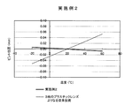
図5は実施例2の撮像レンズの温度変化に対応するピント位置のずれを示すものである。実施例1と同様に、従前のプラスチックレンズでは−20〜60℃の温度変化に対して略±0.05mmのピント位置のずれであったものが、本実施例では該温度変化において±0.01mm以内と良好なものとなっている。 FIG. 5 shows the shift of the focus position corresponding to the temperature change of the imaging lens of the second embodiment. Similar to the first embodiment, the conventional plastic lens has a focus position shift of approximately ± 0.05 mm with respect to a temperature change of -20 to 60 ° C., but in this embodiment, ± 0. It is a good one within 01 mm.
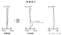
図6は実施例2の撮像レンズの球面収差、非点収差、およびディストーションを示す収差図である。なお、非点収差図には、サジタル像面およびタンジェンシャル像面に対する収差が示されている。これらの収差図においてωは半画角を示す。これらの収差図から明らかなように、実施例2の撮像レンズによれば、各収差を良好に補正することができる。 FIG. 6 is an aberration diagram showing spherical aberration, astigmatism, and distortion of the imaging lens of Example 2. In the astigmatism diagram, aberrations with respect to the sagittal image surface and the tangential image surface are shown. In these aberration diagrams, ω represents a half angle of view. As is apparent from these aberration diagrams, according to the imaging lens of Example 2, each aberration can be corrected satisfactorily.
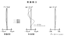
<実施例3>
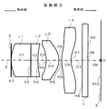
実施例3に係る撮像レンズの概略構成を図7に示す。この撮像レンズの構成も実施例1のものと略同様であり、対応する図面の説明において同一の要素については同一の符号を付し、重複する説明については省略する。ただし、この撮像レンズにおいては、第1レンズL1と第2レンズL2は接合され、絞り2は第1レンズL1の物体側の面に当接するようにして配設されている。すなわち、前絞りの構成とされている。
<Example 3>
A schematic configuration of the imaging lens according to Example 3 is shown in FIG. The configuration of this imaging lens is substantially the same as that of the first embodiment, and in the description of the corresponding drawings, the same elements are denoted by the same reference numerals, and redundant descriptions are omitted. However, in this imaging lens, the first lens L 1 and second lens L 2 are joined, the
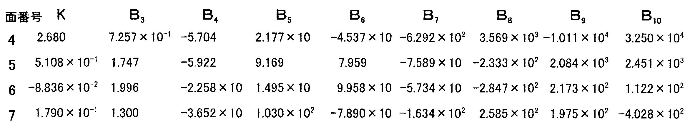
この撮像レンズの各レンズ面の曲率半径R(mm)、各レンズの軸上面間隔D(mm)、各レンズのd線における、屈折率Nおよびアッベ数νの値を表5に示す。なお表中の数字は、物体側からの順番を表すものである(第1面は絞り面および第1レンズL1の物体側の面、第10面は撮像面)。また、表6には、各非球面について、上記非球面式に示される非球面の各定数K、B3、B4、B5、B6、B7、B8、B9、B10の値を示す。 Table 5 shows values of the curvature radius R (mm) of each lens surface of this imaging lens, the axial top surface distance D (mm) of each lens, and the refractive index N and the Abbe number ν in the d-line of each lens. Numerals in the table are those indicating the order from the object side (the surface of the first surface is a diaphragm plane and the first lens L 1 on the object side, the tenth surface is an imaging surface). Table 6 also shows the aspheric constants K, B 3 , B 4 , B 5 , B 6 , B 7 , B 8 , B 9 , and B 10 shown in the above aspheric formula for each aspheric surface. Indicates the value.
また、実施例3の撮像レンズによれば、表7に示すように、条件式(1)〜(6)は全て満足されている。また、レンズ系の全長は1.32mmとされている。 Further, according to the imaging lens of Example 3, as shown in Table 7, all the conditional expressions (1) to (6) are satisfied. The total length of the lens system is 1.32 mm.
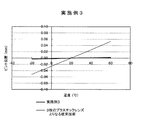
図8は実施例3の撮像レンズの温度変化に対応するピント位置のずれを示すものである。従前のプラスチックレンズでは−20〜60℃の温度変化に対して略±0.05mmのピント位置のずれであったものが、本実施例では該温度変化において±0.005mm以内と全実施例の中で最も良好なものとなっている。 FIG. 8 shows the shift of the focus position corresponding to the temperature change of the imaging lens of the third embodiment. In the conventional plastic lens, the focus position shift is about ± 0.05 mm with respect to the temperature change of −20 to 60 ° C. In this embodiment, the temperature change is within ± 0.005 mm in all the embodiments. It is the best of all.
図9は実施例3の撮像レンズの球面収差、非点収差、およびディストーションを示す収差図である。なお、非点収差図には、サジタル像面およびタンジェンシャル像面に対する収差が示されている。これらの収差図においてωは半画角を示す。これらの収差図から明らかなように、実施例3の撮像レンズによれば、各収差を良好に補正することができる。 FIG. 9 is an aberration diagram illustrating spherical aberration, astigmatism, and distortion of the imaging lens of Example 3. In the astigmatism diagram, aberrations with respect to the sagittal image surface and the tangential image surface are shown. In these aberration diagrams, ω represents a half angle of view. As is apparent from these aberration diagrams, according to the imaging lens of Example 3, each aberration can be corrected satisfactorily.
L1〜L4 レンズ
X 光軸
P 結像位置
1 カバーガラス
2 絞り
3 撮像素子(撮像面)
L 1 ~L 4 lens X optical axis
Claims (3)
0.3<|f1/ f2|<0.8 (1)
νdG1−νdG2>25 (2)
|A1|<1.5×10⁻⁵ (3)
|A2|<1.5×10⁻⁵ (4)
|A3|>1.5×10⁻⁵ (5)
|A4|>1.5×10⁻⁵ (6)
f1:前記第1レンズの焦点距離
f2:前記第2レンズの焦点距離
νdG1:前記第1レンズのアッベ数
νdG2:前記第2レンズのアッベ数
A1:前記第1レンズの線膨張係数
A2:前記第2レンズの線膨張係数
A3:前記第3レンズの線膨張係数
A4:前記第4レンズの線膨張係数 In order from the object side, a first lens composed of a positive lens, a second lens composed of a negative lens having a concave surface facing the image side, a third lens composed of a double-sided aspheric positive lens facing the concave surface toward the object side, and a double-sided aspheric surface An imaging lens comprising a fourth lens composed of a meniscus lens convex toward the object side in the vicinity of the optical axis and satisfying the following conditional expressions (1) to (6).
0.3 <| f 1 / f 2 | <0.8 (1)
ν dG1 −ν dG2 > 25 (2)
| A1 | <1.5 × 10 -5 (3)
| A2 | <1.5 × 10 -5 (4)
| A3 | > 1.5 × 10 -5 (5)
| A4 | > 1.5 × 10 -5 (6)
f 1 : Focal length of the first lens
f 2 : focal length of the second lens ν dG1 : Abbe number of the first lens ν dG2 : Abbe number of the second lens
A1: Linear expansion coefficient of the first lens
A2: Linear expansion coefficient of the second lens
A3: Linear expansion coefficient of the third lens
A4: Linear expansion coefficient of the fourth lens
0.3<|f1/ f2|<0.8 (1)
νdG1−νdG2>25 (2)
f1:前記第1レンズの焦点距離
f2:前記第2レンズの焦点距離
νdG1:前記第1レンズのアッベ数
νdG2:前記第2レンズのアッベ数 In order from the object side, a first lens made of a positive lens made of a glass material, a second lens made of a negative lens made of a glass material with a concave surface facing the image side, and a double-sided aspherical surface with a concave surface facing the object side A third lens composed of a positive lens made of a plastic material, and a fourth lens composed of a meniscus lens convex on the object side in the vicinity of the optical axis formed of a double-sided aspheric plastic material. An imaging lens characterized by satisfying the expressions (1) and (2).
0.3 <| f 1 / f 2 | <0.8 (1)
ν dG1 −ν dG2 > 25 (2)
f 1 : Focal length of the first lens
f 2 : focal length of the second lens ν dG1 : Abbe number of the first lens ν dG2 : Abbe number of the second lens
The imaging lens according to claim 1, wherein both surfaces of the first lens and the second lens are spherical surfaces.
Priority Applications (8)
| Application Number | Priority Date | Filing Date | Title |
|---|---|---|---|
| JP2005195545A JP4980590B2 (en) | 2005-07-04 | 2005-07-04 | Imaging lens |
| KR1020060058473A KR100754340B1 (en) | 2005-07-04 | 2006-06-28 | Imaging lens |
| US11/477,919 US7443611B2 (en) | 2005-07-04 | 2006-06-30 | Imaging lens |
| AT06013750T ATE442602T1 (en) | 2005-07-04 | 2006-07-03 | LENS |
| TW095124092A TWI314997B (en) | 2005-07-04 | 2006-07-03 | Imaging lens |
| EP06013750A EP1742094B1 (en) | 2005-07-04 | 2006-07-03 | Imaging lens |
| DE602006009021T DE602006009021D1 (en) | 2005-07-04 | 2006-07-03 | lens |
| CNB2006100999976A CN100422785C (en) | 2005-07-04 | 2006-07-04 | Imaging lens |
Applications Claiming Priority (1)
| Application Number | Priority Date | Filing Date | Title |
|---|---|---|---|
| JP2005195545A JP4980590B2 (en) | 2005-07-04 | 2005-07-04 | Imaging lens |
Publications (2)
| Publication Number | Publication Date |
|---|---|
| JP2007011237A true JP2007011237A (en) | 2007-01-18 |
| JP4980590B2 JP4980590B2 (en) | 2012-07-18 |
Family
ID=37056607
Family Applications (1)
| Application Number | Title | Priority Date | Filing Date |
|---|---|---|---|
| JP2005195545A Expired - Fee Related JP4980590B2 (en) | 2005-07-04 | 2005-07-04 | Imaging lens |
Country Status (8)
| Country | Link |
|---|---|
| US (1) | US7443611B2 (en) |
| EP (1) | EP1742094B1 (en) |
| JP (1) | JP4980590B2 (en) |
| KR (1) | KR100754340B1 (en) |
| CN (1) | CN100422785C (en) |
| AT (1) | ATE442602T1 (en) |
| DE (1) | DE602006009021D1 (en) |
| TW (1) | TWI314997B (en) |
Cited By (25)
| Publication number | Priority date | Publication date | Assignee | Title |
|---|---|---|---|---|
| KR100711024B1 (en) | 2007-01-23 | 2007-04-24 | 주식회사 세코닉스 | Ultra-small high resolution junction type lens |
| WO2008108011A1 (en) * | 2007-03-08 | 2008-09-12 | Milestone Co., Ltd. | Imaging lens |
| JP2008250052A (en) * | 2007-03-30 | 2008-10-16 | Sanyo Electric Co Ltd | Imaging lens unit and imaging apparatus provided with the same |
| JP2009069193A (en) * | 2007-09-10 | 2009-04-02 | Fujinon Corp | Imaging lens, camera module and imaging equipment |
| US7633690B2 (en) | 2007-04-24 | 2009-12-15 | Samsung Techwin Co., Ltd. | Photographic lens |
| KR100985567B1 (en) | 2008-11-26 | 2010-10-05 | 삼성전기주식회사 | Imaging lens unit |
| KR20110008850A (en) * | 2009-07-21 | 2011-01-27 | 엘지이노텍 주식회사 | Imaging lens |
| WO2011027690A1 (en) * | 2009-09-02 | 2011-03-10 | コニカミノルタオプト株式会社 | Single-focus optical system, image pickup device, and digital apparatus |
| KR101067630B1 (en) * | 2009-05-01 | 2011-09-26 | 주식회사 코렌 | Photographing lens optical system |
| WO2011118554A1 (en) * | 2010-03-26 | 2011-09-29 | コニカミノルタオプト株式会社 | Imaging lens, imaging optical device, and digital equipment |
| KR101100615B1 (en) * | 2010-02-18 | 2012-01-03 | 주식회사 코렌 | Lens optical system |
| US8102607B2 (en) | 2008-12-24 | 2012-01-24 | Sanyo Electric Co., Ltd. | Lens unit and image capturing device |
| JP2012042840A (en) * | 2010-08-23 | 2012-03-01 | Optical Logic Inc | Imaging lens |
| KR101158178B1 (en) * | 2009-09-22 | 2012-06-19 | 삼성전기주식회사 | Optical system for camera |
| US8320057B2 (en) | 2008-10-31 | 2012-11-27 | Sanyo Electric Co., Ltd. | Lens unit and image capturing device |
| US8760776B2 (en) | 2011-08-15 | 2014-06-24 | Largan Precision Co., Ltd. | Optical image capturing lens assembly having four lenses |
| JP5815907B1 (en) * | 2015-07-09 | 2015-11-17 | エーエーシーアコースティックテクノロジーズ(シンセン)カンパニーリミテッドAAC Acoustic Technologies(Shenzhen)Co.,Ltd | Imaging lens |
| KR20160010626A (en) * | 2016-01-07 | 2016-01-27 | 엘지이노텍 주식회사 | Imaging lens |
| KR20160049871A (en) * | 2014-10-28 | 2016-05-10 | 주식회사 코렌 | Photographic lens optical system |
| KR20160076341A (en) * | 2014-12-22 | 2016-06-30 | (주)파트론 | Lens optical system |
| WO2017060950A1 (en) * | 2015-10-05 | 2017-04-13 | オリンパス株式会社 | Imaging device and optical device comprising same |
| WO2017064752A1 (en) * | 2015-10-13 | 2017-04-20 | オリンパス株式会社 | Image pickup device and optical device provided therewith |
| WO2017068726A1 (en) * | 2015-10-23 | 2017-04-27 | オリンパス株式会社 | Imaging device and optical device provided with same |
| KR101791179B1 (en) | 2016-11-08 | 2017-10-27 | 엘지이노텍 주식회사 | Imaging lens |
| CN110737074A (en) * | 2019-10-30 | 2020-01-31 | 广东弘景光电科技股份有限公司 | High-pixel infrared optical system and its application camera module |
Families Citing this family (32)
| Publication number | Priority date | Publication date | Assignee | Title |
|---|---|---|---|---|
| US20030182159A1 (en) * | 2001-12-31 | 2003-09-25 | Bonissone Piero Patrone | Process for summarizing information for insurance underwriting suitable for use by an automated system |
| JP4879600B2 (en) * | 2006-02-15 | 2012-02-22 | 富士フイルム株式会社 | Imaging lens |
| JP4965199B2 (en) * | 2006-09-05 | 2012-07-04 | 富士フイルム株式会社 | Imaging lens |
| KR100799217B1 (en) * | 2006-09-11 | 2008-01-29 | 삼성테크윈 주식회사 | Shooting lens |
| JP3926380B1 (en) * | 2006-12-07 | 2007-06-06 | マイルストーン株式会社 | Imaging lens |
| KR100859037B1 (en) * | 2007-04-30 | 2008-09-17 | 엘지이노텍 주식회사 | Compact optical system |
| JP3976782B1 (en) * | 2007-05-17 | 2007-09-19 | マイルストーン株式会社 | Imaging lens |
| JP5096057B2 (en) * | 2007-07-10 | 2012-12-12 | 富士フイルム株式会社 | Imaging lens, camera module, and imaging device |
| KR101324361B1 (en) * | 2007-12-10 | 2013-11-01 | 엘지디스플레이 주식회사 | Liquid Crystal Display |
| KR100957394B1 (en) * | 2008-01-04 | 2010-05-11 | 엘지이노텍 주식회사 | Imaging lens |
| CN101604065B (en) * | 2008-06-13 | 2012-01-25 | 一品光学工业股份有限公司 | Four-element optical imaging lens with short lens length |
| JP2010020126A (en) * | 2008-07-11 | 2010-01-28 | Fujinon Corp | Imaging lens and imaging apparatus using the imaging lens |
| JP2010049112A (en) * | 2008-08-22 | 2010-03-04 | Sanyo Electric Co Ltd | Lens unit and image capturing device |
| JP5304117B2 (en) * | 2008-09-05 | 2013-10-02 | コニカミノルタ株式会社 | Imaging lens, imaging device, and portable terminal |
| CN101726834A (en) * | 2008-10-14 | 2010-06-09 | 鸿富锦精密工业(深圳)有限公司 | Imaging lens |
| RU2386155C1 (en) * | 2008-11-28 | 2010-04-10 | Открытое акционерное общество "Красногорский завод им. С.А. Зверева" | Large-aperture lens |
| WO2010140515A1 (en) * | 2009-06-03 | 2010-12-09 | コニカミノルタオプト株式会社 | Image pickup lens, image pickup device having image pickup lens, and portable terminal having image pickup device |
| JP5201690B2 (en) * | 2009-10-30 | 2013-06-05 | 株式会社オプトロジック | Imaging lens |
| TWI403781B (en) * | 2010-04-23 | 2013-08-01 | Largan Precision Co Ltd | Photographing optical lens assembly |
| CN102375213B (en) * | 2010-08-10 | 2013-05-15 | 大立光电股份有限公司 | Photographic optical lens group |
| TWI421562B (en) | 2010-12-03 | 2014-01-01 | Largan Precision Co | Optical lens assembly for image taking |
| CN102073127B (en) * | 2011-02-28 | 2012-05-23 | 腾龙光学(佛山)有限公司 | photographic lens |
| TWI432822B (en) | 2011-03-16 | 2014-04-01 | Largan Precision Co | Optical lens assembly for image photographing |
| TWI416162B (en) * | 2011-04-22 | 2013-11-21 | Largan Precision Co | Image taking optical system |
| TWI437309B (en) | 2011-05-12 | 2014-05-11 | Largan Precision Co | Optical lens for image pickup |
| CN103135206B (en) * | 2012-09-07 | 2016-04-20 | 玉晶光电(厦门)有限公司 | Portable electron device and its optical imaging lens |
| CN103135207B (en) * | 2012-11-15 | 2015-07-15 | 玉晶光电(厦门)有限公司 | Portable electronic device and optical imaging lens thereof |
| CN103185952B (en) * | 2012-12-28 | 2017-12-05 | 玉晶光电(厦门)有限公司 | A kind of portable electronic devices and its optical imaging lens |
| EP3032309A4 (en) * | 2013-08-09 | 2017-03-22 | Nikon Corporation | Zoom lens, optical apparatus and zoom lens manufacturing method |
| CN105589183B (en) | 2014-10-24 | 2018-01-09 | 玉晶光电(厦门)有限公司 | Portable electronic devices and its optical imaging lens |
| KR101778071B1 (en) * | 2015-05-14 | 2017-09-13 | 오사카 가스 케미칼 가부시키가이샤 | Imaging Lens System |
| CN106094167B (en) * | 2016-07-18 | 2019-03-22 | 瑞声科技(新加坡)有限公司 | Pick-up lens |
Citations (3)
| Publication number | Priority date | Publication date | Assignee | Title |
|---|---|---|---|---|
| JP2002365529A (en) * | 2001-06-05 | 2002-12-18 | Casio Comput Co Ltd | Shooting lens |
| JP2005004028A (en) * | 2003-06-13 | 2005-01-06 | Olympus Corp | Imaging optical system and imaging apparatus using it |
| JP2005265950A (en) * | 2004-03-16 | 2005-09-29 | Largan Precision Co Ltd | Bifocal lens system and portable equipment |
Family Cites Families (9)
| Publication number | Priority date | Publication date | Assignee | Title |
|---|---|---|---|---|
| JP3424030B2 (en) * | 2001-01-31 | 2003-07-07 | カシオ計算機株式会社 | Shooting lens |
| JP3567327B2 (en) | 2002-05-08 | 2004-09-22 | 富士写真光機株式会社 | Imaging lens |
| JP4334216B2 (en) * | 2002-12-27 | 2009-09-30 | 日本電産コパル株式会社 | Shooting lens |
| KR100509370B1 (en) * | 2002-12-30 | 2005-08-19 | 삼성테크윈 주식회사 | Photographing lens |
| JP4138552B2 (en) | 2003-03-31 | 2008-08-27 | フジノン株式会社 | Imaging lens |
| JP2005024889A (en) | 2003-07-02 | 2005-01-27 | Olympus Corp | Image-formation optical system and imaging apparatus using the same |
| JP2004341013A (en) | 2003-05-13 | 2004-12-02 | Olympus Corp | Imaging optical system and imaging device using the same |
| US7206143B2 (en) * | 2003-05-13 | 2007-04-17 | Olympus Corporation | Image-formation optical system, and imaging system incorporating the same |
| US7277238B2 (en) * | 2005-10-10 | 2007-10-02 | Largan Precision Co., Ltd. | Imaging lens array |
-
2005
- 2005-07-04 JP JP2005195545A patent/JP4980590B2/en not_active Expired - Fee Related
-
2006
- 2006-06-28 KR KR1020060058473A patent/KR100754340B1/en not_active Expired - Fee Related
- 2006-06-30 US US11/477,919 patent/US7443611B2/en active Active
- 2006-07-03 EP EP06013750A patent/EP1742094B1/en not_active Not-in-force
- 2006-07-03 DE DE602006009021T patent/DE602006009021D1/en active Active
- 2006-07-03 AT AT06013750T patent/ATE442602T1/en not_active IP Right Cessation
- 2006-07-03 TW TW095124092A patent/TWI314997B/en not_active IP Right Cessation
- 2006-07-04 CN CNB2006100999976A patent/CN100422785C/en not_active Expired - Fee Related
Patent Citations (3)
| Publication number | Priority date | Publication date | Assignee | Title |
|---|---|---|---|---|
| JP2002365529A (en) * | 2001-06-05 | 2002-12-18 | Casio Comput Co Ltd | Shooting lens |
| JP2005004028A (en) * | 2003-06-13 | 2005-01-06 | Olympus Corp | Imaging optical system and imaging apparatus using it |
| JP2005265950A (en) * | 2004-03-16 | 2005-09-29 | Largan Precision Co Ltd | Bifocal lens system and portable equipment |
Cited By (40)
| Publication number | Priority date | Publication date | Assignee | Title |
|---|---|---|---|---|
| JP2008181075A (en) * | 2007-01-23 | 2008-08-07 | Sekonix Co Ltd | Micro high-definition compound imaging lens |
| KR100711024B1 (en) | 2007-01-23 | 2007-04-24 | 주식회사 세코닉스 | Ultra-small high resolution junction type lens |
| WO2008108011A1 (en) * | 2007-03-08 | 2008-09-12 | Milestone Co., Ltd. | Imaging lens |
| JP2008250052A (en) * | 2007-03-30 | 2008-10-16 | Sanyo Electric Co Ltd | Imaging lens unit and imaging apparatus provided with the same |
| US7633690B2 (en) | 2007-04-24 | 2009-12-15 | Samsung Techwin Co., Ltd. | Photographic lens |
| KR100940235B1 (en) * | 2007-04-24 | 2010-02-04 | 삼성테크윈 주식회사 | Shooting lens |
| JP2009069193A (en) * | 2007-09-10 | 2009-04-02 | Fujinon Corp | Imaging lens, camera module and imaging equipment |
| US8320057B2 (en) | 2008-10-31 | 2012-11-27 | Sanyo Electric Co., Ltd. | Lens unit and image capturing device |
| KR100985567B1 (en) | 2008-11-26 | 2010-10-05 | 삼성전기주식회사 | Imaging lens unit |
| US8102607B2 (en) | 2008-12-24 | 2012-01-24 | Sanyo Electric Co., Ltd. | Lens unit and image capturing device |
| KR101067630B1 (en) * | 2009-05-01 | 2011-09-26 | 주식회사 코렌 | Photographing lens optical system |
| KR101586024B1 (en) | 2009-07-21 | 2016-01-15 | 엘지이노텍 주식회사 | Imaging lens |
| KR20110008850A (en) * | 2009-07-21 | 2011-01-27 | 엘지이노텍 주식회사 | Imaging lens |
| WO2011027690A1 (en) * | 2009-09-02 | 2011-03-10 | コニカミノルタオプト株式会社 | Single-focus optical system, image pickup device, and digital apparatus |
| US8654242B2 (en) | 2009-09-02 | 2014-02-18 | Konica Minolta Opto, Inc. | Single-focus optical system, image pickup device, and digital apparatus |
| JP5472307B2 (en) * | 2009-09-02 | 2014-04-16 | コニカミノルタ株式会社 | Single focus optical system, imaging device and digital device |
| KR101158178B1 (en) * | 2009-09-22 | 2012-06-19 | 삼성전기주식회사 | Optical system for camera |
| US8320060B2 (en) | 2009-09-22 | 2012-11-27 | Samsung Electro-Mechanics Co., Ltd. | Optical system for camera |
| KR101100615B1 (en) * | 2010-02-18 | 2012-01-03 | 주식회사 코렌 | Lens optical system |
| WO2011118554A1 (en) * | 2010-03-26 | 2011-09-29 | コニカミノルタオプト株式会社 | Imaging lens, imaging optical device, and digital equipment |
| US8917457B2 (en) | 2010-03-26 | 2014-12-23 | Konica Minolta Advanced Layers, Inc. | Imaging lens, imaging optical device, and digital equipment |
| JP2012042840A (en) * | 2010-08-23 | 2012-03-01 | Optical Logic Inc | Imaging lens |
| US8760776B2 (en) | 2011-08-15 | 2014-06-24 | Largan Precision Co., Ltd. | Optical image capturing lens assembly having four lenses |
| KR20160049871A (en) * | 2014-10-28 | 2016-05-10 | 주식회사 코렌 | Photographic lens optical system |
| KR101660218B1 (en) * | 2014-10-28 | 2016-09-27 | 주식회사 코렌 | Photographic lens optical system |
| KR20160076341A (en) * | 2014-12-22 | 2016-06-30 | (주)파트론 | Lens optical system |
| KR101661922B1 (en) | 2014-12-22 | 2016-10-04 | (주)파트론 | Lens optical system |
| JP5815907B1 (en) * | 2015-07-09 | 2015-11-17 | エーエーシーアコースティックテクノロジーズ(シンセン)カンパニーリミテッドAAC Acoustic Technologies(Shenzhen)Co.,Ltd | Imaging lens |
| WO2017060950A1 (en) * | 2015-10-05 | 2017-04-13 | オリンパス株式会社 | Imaging device and optical device comprising same |
| JPWO2017060950A1 (en) * | 2015-10-05 | 2018-07-26 | オリンパス株式会社 | Imaging apparatus and optical apparatus including the same |
| WO2017064752A1 (en) * | 2015-10-13 | 2017-04-20 | オリンパス株式会社 | Image pickup device and optical device provided therewith |
| JPWO2017064752A1 (en) * | 2015-10-13 | 2018-08-02 | オリンパス株式会社 | Imaging apparatus and optical apparatus including the same |
| US10488634B2 (en) | 2015-10-13 | 2019-11-26 | Olympus Corporation | Image pickup apparatus and optical apparatus using the same |
| WO2017068726A1 (en) * | 2015-10-23 | 2017-04-27 | オリンパス株式会社 | Imaging device and optical device provided with same |
| JPWO2017068726A1 (en) * | 2015-10-23 | 2018-08-09 | オリンパス株式会社 | Imaging apparatus and optical apparatus including the same |
| US10634884B2 (en) | 2015-10-23 | 2020-04-28 | Olympus Corporation | Image pickup apparatus and optical apparatus using the same |
| KR101676424B1 (en) | 2016-01-07 | 2016-11-15 | 엘지이노텍 주식회사 | Imaging lens |
| KR20160010626A (en) * | 2016-01-07 | 2016-01-27 | 엘지이노텍 주식회사 | Imaging lens |
| KR101791179B1 (en) | 2016-11-08 | 2017-10-27 | 엘지이노텍 주식회사 | Imaging lens |
| CN110737074A (en) * | 2019-10-30 | 2020-01-31 | 广东弘景光电科技股份有限公司 | High-pixel infrared optical system and its application camera module |
Also Published As
| Publication number | Publication date |
|---|---|
| TWI314997B (en) | 2009-09-21 |
| EP1742094A1 (en) | 2007-01-10 |
| DE602006009021D1 (en) | 2009-10-22 |
| CN1892278A (en) | 2007-01-10 |
| KR20070004425A (en) | 2007-01-09 |
| ATE442602T1 (en) | 2009-09-15 |
| US20070014033A1 (en) | 2007-01-18 |
| JP4980590B2 (en) | 2012-07-18 |
| EP1742094B1 (en) | 2009-09-09 |
| CN100422785C (en) | 2008-10-01 |
| US7443611B2 (en) | 2008-10-28 |
| TW200710427A (en) | 2007-03-16 |
| KR100754340B1 (en) | 2007-08-31 |
Similar Documents
| Publication | Publication Date | Title |
|---|---|---|
| JP4980590B2 (en) | Imaging lens | |
| TWI437311B (en) | Optical lens assembly for image taking | |
| JP5252842B2 (en) | Imaging lens | |
| CN108474926B (en) | Objective optical system | |
| JP5818209B2 (en) | Macro lens | |
| TWI435105B (en) | Optical lens assembly for image pickup | |
| KR101553835B1 (en) | Large diameter standard lens | |
| CN109445067A (en) | Optical imaging lens and imaging device | |
| CN107111112B (en) | Objective optical system for endoscope | |
| JP5571255B2 (en) | Objective optical system and endoscope apparatus using the same | |
| JP2005345919A (en) | Imaging lens | |
| JP2005208236A (en) | Single focus lens | |
| JP4098586B2 (en) | Zoom lens | |
| CN109923458B (en) | Objective optical system | |
| CN112424665B (en) | Endoscope Optical System | |
| JP5571256B2 (en) | Objective optical system and endoscope apparatus using the same | |
| JP4634012B2 (en) | 2 group zoom lens | |
| JP2008275832A (en) | Imaging lens | |
| JP3925748B2 (en) | Small lens | |
| JP2005173319A (en) | Imaging lens | |
| US20210072516A1 (en) | Lens system and image pickup apparatus | |
| JP2008129349A (en) | Imaging lens and image pickup apparatus equipped with same | |
| JP4965234B2 (en) | Zoom lens | |
| JP2009042333A (en) | Photographic lens | |
| JPH10227973A (en) | Photographic lens |
Legal Events
| Date | Code | Title | Description |
|---|---|---|---|
| A621 | Written request for application examination |
Free format text: JAPANESE INTERMEDIATE CODE: A621 Effective date: 20080521 |
|
| A711 | Notification of change in applicant |
Free format text: JAPANESE INTERMEDIATE CODE: A711 Effective date: 20100617 |
|
| A977 | Report on retrieval |
Free format text: JAPANESE INTERMEDIATE CODE: A971007 Effective date: 20110401 |
|
| A131 | Notification of reasons for refusal |
Free format text: JAPANESE INTERMEDIATE CODE: A131 Effective date: 20110719 |
|
| A521 | Request for written amendment filed |
Free format text: JAPANESE INTERMEDIATE CODE: A523 Effective date: 20110915 |
|
| A02 | Decision of refusal |
Free format text: JAPANESE INTERMEDIATE CODE: A02 Effective date: 20111108 |
|
| A521 | Request for written amendment filed |
Free format text: JAPANESE INTERMEDIATE CODE: A523 Effective date: 20120127 |
|
| A911 | Transfer to examiner for re-examination before appeal (zenchi) |
Free format text: JAPANESE INTERMEDIATE CODE: A911 Effective date: 20120206 |
|
| TRDD | Decision of grant or rejection written | ||
| A01 | Written decision to grant a patent or to grant a registration (utility model) |
Free format text: JAPANESE INTERMEDIATE CODE: A01 Effective date: 20120417 |
|
| A01 | Written decision to grant a patent or to grant a registration (utility model) |
Free format text: JAPANESE INTERMEDIATE CODE: A01 |
|
| A61 | First payment of annual fees (during grant procedure) |
Free format text: JAPANESE INTERMEDIATE CODE: A61 Effective date: 20120419 |
|
| FPAY | Renewal fee payment (event date is renewal date of database) |
Free format text: PAYMENT UNTIL: 20150427 Year of fee payment: 3 |
|
| R150 | Certificate of patent or registration of utility model |
Ref document number: 4980590 Country of ref document: JP Free format text: JAPANESE INTERMEDIATE CODE: R150 Free format text: JAPANESE INTERMEDIATE CODE: R150 |
|
| R250 | Receipt of annual fees |
Free format text: JAPANESE INTERMEDIATE CODE: R250 |
|
| R250 | Receipt of annual fees |
Free format text: JAPANESE INTERMEDIATE CODE: R250 |
|
| R250 | Receipt of annual fees |
Free format text: JAPANESE INTERMEDIATE CODE: R250 |
|
| R250 | Receipt of annual fees |
Free format text: JAPANESE INTERMEDIATE CODE: R250 |
|
| S111 | Request for change of ownership or part of ownership |
Free format text: JAPANESE INTERMEDIATE CODE: R313113 |
|
| R350 | Written notification of registration of transfer |
Free format text: JAPANESE INTERMEDIATE CODE: R350 |
|
| R250 | Receipt of annual fees |
Free format text: JAPANESE INTERMEDIATE CODE: R250 |
|
| R250 | Receipt of annual fees |
Free format text: JAPANESE INTERMEDIATE CODE: R250 |
|
| S111 | Request for change of ownership or part of ownership |
Free format text: JAPANESE INTERMEDIATE CODE: R313113 |
|
| R371 | Transfer withdrawn |
Free format text: JAPANESE INTERMEDIATE CODE: R371 |
|
| R350 | Written notification of registration of transfer |
Free format text: JAPANESE INTERMEDIATE CODE: R350 |
|
| R250 | Receipt of annual fees |
Free format text: JAPANESE INTERMEDIATE CODE: R250 |
|
| LAPS | Cancellation because of no payment of annual fees |