JP2007017635A - Stereoscopic image display apparatus and stereoscopic image display method - Google Patents
Stereoscopic image display apparatus and stereoscopic image display method Download PDFInfo
- Publication number
- JP2007017635A JP2007017635A JP2005198075A JP2005198075A JP2007017635A JP 2007017635 A JP2007017635 A JP 2007017635A JP 2005198075 A JP2005198075 A JP 2005198075A JP 2005198075 A JP2005198075 A JP 2005198075A JP 2007017635 A JP2007017635 A JP 2007017635A
- Authority
- JP
- Japan
- Prior art keywords
- pixel
- image display
- image
- composite image
- directional
- Prior art date
- Legal status (The legal status is an assumption and is not a legal conclusion. Google has not performed a legal analysis and makes no representation as to the accuracy of the status listed.)
- Pending
Links
Images


Landscapes
- Stereoscopic And Panoramic Photography (AREA)
- Testing, Inspecting, Measuring Of Stereoscopic Televisions And Televisions (AREA)
Abstract
【課題】 画素ごとに指向性画像の透過光が大きく拡がらないようにすることによって、立体画像における輝度ムラの発生を防ぐ。
【解決手段】 本発明に係る立体画像表示装置1は、複数の視点から観察した表示対象物の指向性画像を蓄積するように構成されている指向性画像蓄積部11と、所定規則によって指向性画像の各画素を並べ変えることによって合成画像を生成するように構成されている合成画像生成部12と、合成画像を表示するように構成されている合成画像表示部13と、合成画像表示部13に表示された合成画像の各画素を透過した光の進行方向を決定するように構成されている指向性方向決定部14とを具備している。合成画像表示部13における各画素の形状は、指向性方向決定部14の中心軸14Aと平行な辺を有する矩形である。
【選択図】 図3PROBLEM TO BE SOLVED: To prevent occurrence of luminance unevenness in a stereoscopic image by preventing transmitted light of a directional image from spreading greatly for each pixel.
A stereoscopic image display device 1 according to the present invention includes a directional image storage unit 11 configured to store directional images of a display object observed from a plurality of viewpoints, and directivity according to a predetermined rule. A composite image generation unit 12 configured to generate a composite image by rearranging each pixel of the image, a composite image display unit 13 configured to display the composite image, and a composite image display unit 13 And a directivity direction determination unit 14 configured to determine a traveling direction of light transmitted through each pixel of the composite image displayed on the screen. The shape of each pixel in the composite image display unit 13 is a rectangle having sides parallel to the central axis 14 </ b> A of the directivity direction determination unit 14.
[Selection] Figure 3
Description
本発明は、表示対象物を立体画像として表示する立体画像表示装置及び立体画像表示方法に関する。 The present invention relates to a stereoscopic image display apparatus and a stereoscopic image display method for displaying a display object as a stereoscopic image.
従来、表示対象物を立体画像として表示する技術として「ステレオ視方式」が知られている。かかるステレオ視方式は、スリット(パララックスバリア)等を利用して、観察者の左右の目に異なる画像を提示し、両眼視差によって当該観察者に立体を知覚させる方式である。 Conventionally, a “stereo viewing method” is known as a technique for displaying a display object as a stereoscopic image. Such a stereo viewing method is a method of presenting different images to the left and right eyes of the observer using a slit (parallax barrier) or the like, and causing the observer to perceive a solid by binocular parallax.
かかるステレオ視方式では、観察者の左右の目にそれぞれ整合した画像が入る(見える)ようにする必要があるため、立体画像を表示することができる視点位置が固定されてしまうため、観察者が頭を動かした場合であっても立体を知覚することができるという「運動視差」を実現できない。 In such a stereo viewing method, it is necessary to allow (view) images that match each of the left and right eyes of the observer, so that the viewpoint position at which a stereoscopic image can be displayed is fixed. Even if the head is moved, the “motion parallax” in which a solid can be perceived cannot be realized.
かかる運動視差を実現するために、従来の単一視点のステレオ視方式を、複数視点のステレオ視方式に拡張する技術が知られている。 In order to realize such motion parallax, a technique for extending a conventional single viewpoint stereo vision system to a multiple viewpoint stereo vision system is known.
しかしながら、例えば、パララックスバリア方式では、開口部が縦ストライプ形状であるため、当該パララックスバリア方式を多視点に応用すると、水平方向の解像度が劣化してしまうという問題点があった。 However, for example, in the parallax barrier method, since the opening has a vertical stripe shape, there is a problem that when the parallax barrier method is applied to multiple viewpoints, the resolution in the horizontal direction is deteriorated.
かかる問題点を解決するために、階段状に開口部を持つ「斜めバリア方式」或いは「レンチキュラーシートを斜めに貼り付けた方式」を採用して、複数の視点から観察した画像を、水平方向のみならず垂直方向にも分散させることで、水平方向の解像度を維持しつつ、複数視点のステレオ視方式を実現する表示装置が提案されている(特許文献1参照)。 In order to solve this problem, the “oblique barrier method” or “the method of attaching lenticular sheets obliquely” with openings in a staircase is adopted, and images observed from multiple viewpoints are only in the horizontal direction. In addition, there has been proposed a display device that realizes a multi-viewpoint stereo viewing method while maintaining horizontal resolution by dispersing in the vertical direction as well (see Patent Document 1).
一方、人間の立体知覚には、両眼視差、ピント調節、輻輳、運動視差の4つの要因が存在する。 On the other hand, human stereoscopic perception includes four factors: binocular parallax, focus adjustment, convergence, and motion parallax.
従来の立体画像表示方式では、両眼視差のみを利用しているため、両眼視差により知覚される奥行き感及び目のピント調節の位置が異なることに起因する眼疲労等が起きやすいという問題点があった。 Since conventional stereoscopic image display methods use only binocular parallax, eye fatigue or the like is likely to occur due to different perceived depth perception and binocular parallax positions. was there.
そこで、従来のステレオ視方式において、視点の数を十分に多くすることで、立体知覚についての4つの要因を全て満たす立体画像表示が可能となる。 Therefore, in the conventional stereo vision system, by sufficiently increasing the number of viewpoints, it is possible to display a stereoscopic image that satisfies all four factors regarding stereoscopic perception.
しかしながら、かかるステレオ視方式では、立体知覚できる範囲(視域)は、左右の眼に視点画像が正確に投影される位置(表示装置から特定の距離だけ離れている特定の位置)に限られてしまうという問題点があった。 However, in such a stereo vision system, the range (viewing area) in which stereoscopic perception can be performed is limited to a position (a specific position away from the display device by a specific distance) at which the viewpoint image is accurately projected on the left and right eyes. There was a problem of end.
そこで、このような視域の制約を緩和して表示装置からの距離に影響しないステレオ視方式として、高密度指向性画像提示方式が提案されている(特許文献2参照)。 Therefore, a high-density directional image presentation method has been proposed as a stereo viewing method that relaxes such restrictions on the viewing zone and does not affect the distance from the display device (see Patent Document 2).
かかる高密度指向性画像提示方式は、複数の画像発生源(小さな液晶パネル)において、水平位置が一致しないように水平方向及び垂直方向に(すなわち、2次元的に)画像を配置し、複数のアフォーカル光学系で、複数の画像発生源で生成される画像を異なる水平表示角度範囲に平行投影し、垂直方向拡散板で表示角度範囲を垂直方向のみに広げて、全ての画像に共通な垂直表示角度範囲を作ることで、垂直方向の表示方向の違いを解消し、水平方向に表示方向の異なる複数の画像を、重なりを持たせて表示するようにした方式である。 Such a high-density directional image presentation method arranges images in a horizontal direction and a vertical direction (that is, two-dimensionally) so that horizontal positions do not coincide with each other in a plurality of image generation sources (small liquid crystal panels). An afocal optical system projects images generated by multiple image generation sources in parallel to different horizontal display angle ranges, and a vertical diffuser spreads the display angle range only in the vertical direction, making it a common vertical for all images. By creating a display angle range, a difference in the display direction in the vertical direction is eliminated, and a plurality of images having different display directions in the horizontal direction are displayed with overlapping.
かかる高密度指向性画像提示方式では、光学系が大がかりとなり、小型化が困難であるという問題点があった。 In such a high-density directional image presentation method, there is a problem that the optical system becomes large and it is difficult to reduce the size.
かかる問題点を解決するために、高密度指向性画像提示方式を応用して、薄型画像表示装置で実現したレンチキュラーシートを、アフォーカル光学系として利用し、2次元画像表示装置に斜めに貼付ける方式が提案されている(非特許文献1参照)。かかる方式は、図6に示すように、2次元画像表示装置(例えば、液晶パネル)にレンチキュラーシート14を傾けて貼り付けることで実現できる。
しかしながら、上述のレンチキュラーシートを2次元画像表示装置に斜めに貼り付ける方式では、2次元画像表示装置に表示される画素の1辺(開口領域の方向)と、レンチキュラーシートを構成するシリンドリカルレンズ(かまぼこ型のレンズ)の曲面の中心軸(中心線)が平行でないために、各画素に入射する光の位置が大きく異なり、各画素を透過した光の進行方向が大きく変わってしまうという問題点があった。 However, in the method in which the above lenticular sheet is attached to the two-dimensional image display device at an angle, one side of the pixel (direction of the opening region) displayed on the two-dimensional image display device and a cylindrical lens (kamaboko) constituting the lenticular sheet. Since the center axis (center line) of the curved surface of the lens of the mold is not parallel, the position of the light incident on each pixel is greatly different, and the traveling direction of the light transmitted through each pixel is greatly changed. It was.
すなわち、上述のレンチキュラーシートを2次元画像表示装置に斜めに貼り付ける方式では、同じ画素を透過した光が、大きく拡がってしまい、輝度値のムラが発生するという問題点があった。 That is, the above-described method of attaching the lenticular sheet obliquely to the two-dimensional image display device has a problem in that the light transmitted through the same pixel spreads greatly, resulting in uneven brightness values.
図6乃至図9を参照して、かかる問題点について具体的に説明する。 This problem will be specifically described with reference to FIGS.
上述の方式では、図6に示すように、2次元画像表示装置に、12の視線方向a〜lに対応する指向性画像の各画素を、所定規則によって並び替えることによって生成された1枚の画像(合成画像)を表示する。 In the above-described method, as shown in FIG. 6, a one-dimensional image generated by rearranging each pixel of a directional image corresponding to 12 line-of-sight directions a to l according to a predetermined rule on a two-dimensional image display device. Display an image (composite image).
図6の例では、点線で囲まれた部分が、立体画像の1つのピクセル(以下、3Dピクセル)に対応し、視線方向a〜lとして12方向を有する3Dピクセルが表示されることになる。 In the example of FIG. 6, a portion surrounded by a dotted line corresponds to one pixel (hereinafter, 3D pixel) of the stereoscopic image, and 3D pixels having 12 directions as the line-of-sight directions a to l are displayed.
具体的には、例えば、指向性方向cに対応する画素は、3Dピクセルの中で、赤(R)の画素、緑(G)の画素、青(B)の画素という3つの画素である。 Specifically, for example, the pixels corresponding to the directivity direction c are three pixels of a 3D pixel, that is, a red (R) pixel, a green (G) pixel, and a blue (B) pixel.
かかる場合、図7に示すように、レンチキュラーシート14を構成するシリンドリカルレンズ140と各画素(例えば、画素A)との位置関係は、画素Aの1辺とシリンドリカルレンズ140の中心軸14Aとの関係が、斜めの位置関係となる(すなわち、画素Aの1辺とシリンドリカルレンズ140の中心軸14Aとが平行ではない)。
In this case, as shown in FIG. 7, the positional relationship between the
すなわち、従来の立体画像表示装置では、シリンドリカルレンズ140の中心軸14Aと画素Aの中心線とが平行でないため、図8に示すように、画素Aの開口領域(r1−r2)が広くなり、当該画素の開口領域を透過した光は、シリンドリカルレンズ140の異なる位置に入射することになり、図9に示すように、透過光の投影方向が大きく拡がってしまう。
That is, in the conventional stereoscopic image display device, since the
したがって、図9に示すように、画素Aとシリンドリカルレンズ140の中心軸14Aとの距離に応じて、画素Aの開口領域を透過する光量が変わることになり、シリンドリカルレンズ140の中心軸14Aに垂直な方向において、画素Aの開口領域内の位置によって輝度が異なる。
Therefore, as shown in FIG. 9, the amount of light transmitted through the aperture region of the pixel A changes according to the distance between the pixel A and the
そこで、本発明は、以上の点に鑑みてなされたもので、画素ごとに指向性画像の透過光が大きく拡がらないようにすることによって、立体画像における輝度ムラの発生を防ぐことができる立体画像表示装置及び立体画像表示方法を提供することを目的とする。 Therefore, the present invention has been made in view of the above points, and by preventing the transmitted light of the directional image from greatly spreading for each pixel, it is possible to prevent the occurrence of uneven brightness in the stereoscopic image. An object is to provide an image display device and a stereoscopic image display method.
本発明の第1の特徴は、表示対象物を立体画像として表示する立体画像表示装置であって、複数の視点から観察した前記表示対象物の指向性画像を蓄積するように構成されている指向性画像蓄積部と、所定規則によって前記指向性画像の各画素を並べ変えることによって合成画像を生成するように構成されている合成画像生成部と、前記合成画像を表示するように構成されている合成画像表示部と、前記合成画像表示部に表示された合成画像の各画素を透過した光の進行方向を決定するように構成されている指向性方向決定部とを具備しており、前記合成画像表示部における前記各画素の開口形状が、前記指向性方向決定部の中心軸と平行な辺を有する矩形であることを要旨とする。 A first feature of the present invention is a stereoscopic image display device that displays a display object as a stereoscopic image, and is configured to accumulate directional images of the display object observed from a plurality of viewpoints. A composite image generation unit configured to generate a composite image by rearranging pixels of the directivity image according to a predetermined rule; and a display unit configured to display the composite image. A composite image display unit; and a directivity direction determination unit configured to determine a traveling direction of light transmitted through each pixel of the composite image displayed on the composite image display unit. The gist is that the opening shape of each pixel in the image display unit is a rectangle having a side parallel to the central axis of the directivity direction determining unit.
本発明の第1の特徴において、前記矩形が、平行四辺形であってもよい。 In the first feature of the present invention, the rectangle may be a parallelogram.
本発明の第1の特徴において、前記指向性方向決定部が、レンチキュラーシートによって構成されており、前記指向性方向決定部における中心軸が、前記レンチキュラーシートを構成するシリンドリカルレンズの中心軸であっていてもよい。 In the first aspect of the present invention, the directivity direction determining unit is configured by a lenticular sheet, and the central axis of the directivity direction determining unit is a central axis of a cylindrical lens that configures the lenticular sheet. May be.
本発明の第2の特徴は、表示対象物を立体画像として表示する立体画像表示方法であって、複数の視点から観察した前記表示対象物の指向性画像を蓄積するように構成されている指向性画像蓄積部から、所定の表示対象物の指向性画像を抽出する工程と、所定規則によって前記所定の表示対象物の指向性画像の各画素を並べ変えることによって合成画像を生成する工程と、前記合成画像を2次元画像表示装置に表示する工程と、前記2次元画像表示装置に表示された前記合成画像の各画素を透過した光が、レンチキュラーシートを構成するシリンドリカルレンズを介して進む工程とを有しており、前記各画素の開口形状が、前記シリンドリカルレンズの中心軸と平行な辺を有する矩形であることを要旨とする。 A second feature of the present invention is a stereoscopic image display method for displaying a display object as a stereoscopic image, the directivity image being configured to accumulate directional images of the display object observed from a plurality of viewpoints. Extracting a directional image of a predetermined display object from the directional image storage unit, generating a composite image by rearranging each pixel of the directional image of the predetermined display object according to a predetermined rule, A step of displaying the composite image on a two-dimensional image display device, and a step of light transmitted through each pixel of the composite image displayed on the two-dimensional image display device traveling through a cylindrical lens constituting a lenticular sheet; The opening shape of each pixel is a rectangle having a side parallel to the central axis of the cylindrical lens.
以上説明したように、本発明によれば、画素ごとに指向性画像の透過光が大きく拡がらないようにすることによって、立体画像における輝度ムラの発生を防ぐことができる立体画像表示装置及び立体画像表示方法を提供することができる。 As described above, according to the present invention, by preventing the transmitted light of the directional image from greatly spreading for each pixel, it is possible to prevent the occurrence of luminance unevenness in the stereoscopic image and the stereoscopic image. An image display method can be provided.
(本発明の第1の実施形態に係る立体画像表示装置の構成)
図1乃至図4を参照して、本発明の第1の実施形態に係る立体画像表示装置1の構成について説明する。本実施形態に係る立体画像表示装置1は、表示対象物を立体画像として表示するように構成されている。なお、本明細書において、画像とは、静止画及び動画の双方を含むものとする。
(Configuration of stereoscopic image display device according to first embodiment of the present invention)
With reference to FIG. 1 thru | or FIG. 4, the structure of the three-dimensional image display apparatus 1 which concerns on the 1st Embodiment of this invention is demonstrated. The stereoscopic image display device 1 according to the present embodiment is configured to display a display object as a stereoscopic image. In this specification, an image includes both a still image and a moving image.
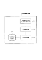
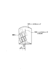
図1に示すように、本実施形態に係る立体画像表示装置1は、指向性画像蓄積部11と、合成画像生成部12と、合成画像表示部13と、指向性方向決定部14とを具備している。
As shown in FIG. 1, the stereoscopic image display apparatus 1 according to this embodiment includes a directional
指向性画像蓄積部11は、複数の視点から観察した表示対象物の指向性画像を蓄積するように構成されている。図2において、「複数の視点から観察した表示対象物の指向性画像」は、それぞれ、複数の視線方向a〜lに対応するR、G、Bの各画素によって構成されている。なお、本明細書において、視線方向、指向性方向、指向性画像の投影方向は、同義であるものとする。
The directivity
また、指向性画像蓄積部11は、合成画像生成部12からの要求に応じて、特定箇所の指向性画像を送信するように構成されている。
In addition, the directivity
合成画像生成部1は、所定規則によって指向性画像の各画素を並べ変えることによって合成画像を生成するように構成されている。 The composite image generation unit 1 is configured to generate a composite image by rearranging the pixels of the directional image according to a predetermined rule.
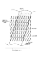
具体的には、図2に示すように、合成画像生成部12は、12の視線方向a〜lに対応する指向性画像の各画素R、G、Bを、所定規則によって並び替えることによって1枚の合成画像を生成する。
Specifically, as illustrated in FIG. 2, the composite
合成画像表示部13は、合成画像生成部12によって生成された合成画像を表示するように構成されている。具体的には、合成画像表示部13は、2次元画像表示装置(例えば、液晶ディスプレイ等)によって構成されている。
The composite
図2の例では、3Dピクセル(点線で囲まれた部分)に12の視線方向a〜lに対応するR、G、Bの画素が含まれているため、観察者は、12の視線方向a〜lから、表示対象物の立体画像を観察することができる。言い換えると、観察者は、12の視線方向a〜l以外の視線方向からは、表示対象物の立体画像を観察することができない。 In the example of FIG. 2, the 3D pixel (portion surrounded by a dotted line) includes R, G, and B pixels corresponding to 12 line-of-sight directions a to l. From ˜l, a stereoscopic image of the display object can be observed. In other words, the observer cannot observe a stereoscopic image of the display object from a viewing direction other than the 12 viewing directions a to l.
したがって、観察者は、各指向性画像の投影方向から合成画像表示部13を観察すると、当該投影方向の指向性画像のみが観察でき、頭を動かして観察することで、異なる投影方向の指向性画像を観察することができる。
Therefore, when the observer observes the composite
つまり、観察者は、頭を動かすことで、異なる視点からの立体画像を観察することができ、運動視差を実現した立体画像を表示することができる。 That is, the observer can observe a stereoscopic image from different viewpoints by moving his / her head, and can display a stereoscopic image realizing motion parallax.
指向性方向決定部14は、合成画像表示部13に表示された合成画像の各画素(の開口領域)を透過した光の進行方向を決定するように構成されている。
The directivity
具体的には、指向性方向決定部14は、図2に示すように、2次元画像表示装置に斜めに貼り付けられたレンチキュラーシートによって構成されている。
Specifically, the directivity
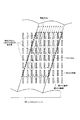
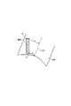
本実施形態に係る立体画像表示装置1では、図3に示すように、合成画像表示部13における各画素の開口形状は、指向性方向決定部14の中心軸14Aと平行な辺を有する矩形(例えば、平行四辺形)である。ここで、指向性方向決定部14の中心軸14Aは、レンチキュラーシート14を構成する各シリンドリカルレンズ140の中心軸14Aである。
In the stereoscopic image display device 1 according to the present embodiment, as illustrated in FIG. 3, the opening shape of each pixel in the composite
すなわち、本実施形態に係る立体画像表示装置1では、レンチキュラーシート14を構成する各シリンドリカルレンズ140の焦点距離の位置に、各画素が配置されるように、指向性方向決定部14及び合成画像表示部13を構成する。
That is, in the stereoscopic image display device 1 according to the present embodiment, the directivity
その結果、画素Aの開口領域を透過した光は、シリンドリカルレンズ140の中心軸14Aに水平な方向では、均等に拡散され、シリンドリカルレンズ140の中心軸14Aに垂直な方向では、平行光として投影されることになる。
As a result, the light transmitted through the aperture region of the pixel A is evenly diffused in the direction horizontal to the
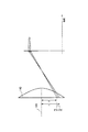
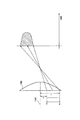
ここで、本実施形態に係る立体画像表示装置1では、シリンドリカルレンズ140の中心軸14Aと画素Aの中心線とが平行であるため、図4に示すように、画素Aの開口領域(r1−r2)が狭くなり、当該画素の開口領域を透過した光は、シリンドリカルレンズ140のほとんど同じ位置に入射することになり、図5に示すように、透過光の投影方向が大きく拡がることない。
Here, in the stereoscopic image display apparatus 1 according to the present embodiment, since the
その結果、本実施形態に係る立体画像表示装置1では、図5に示すように、画素Aの開口領域を透過した光は、輝度変化が略矩形形状になり、輝度ムラが発生しなくなる。 As a result, in the stereoscopic image display device 1 according to the present embodiment, as shown in FIG. 5, the light that has passed through the aperture region of the pixel A has a substantially rectangular change in luminance, and luminance unevenness does not occur.
(本発明の第1の実施形態に係る立体画像表示装置の作用・効果)
本発明の第1の実施形態に係る立体画像表示装置1によれば、合成画像表示部13上の各画素が、レンチキュラーシート14を構成する各シリンドリカルレンズ140に対して平行に配置されることによって、当該画素を透過した光は、ほとんど同じ方向に進むことになる。
(Operation and effect of the stereoscopic image display apparatus according to the first embodiment of the present invention)
According to the stereoscopic image display device 1 according to the first embodiment of the present invention, each pixel on the composite
また、本発明の第1の実施形態に係る立体画像表示装置1によれば、各画素の開口形状が、各シリンドリカルレンズ140の中心軸14Aと平行であるため、各画素を透過した光が、当該中心軸14Aに垂直な方向において、ほとんど輝度の偏りが無くなり、輝度ムラもなくすことができる。
Further, according to the stereoscopic image display device 1 according to the first embodiment of the present invention, the aperture shape of each pixel is parallel to the
1…立体画像表示装置
11…指向性画像蓄積部
12…合成画像生成部
13…合成画像表示部
14…指向性方向決定部
DESCRIPTION OF SYMBOLS 1 ... Stereoscopic
Claims (4)
複数の視点から観察した前記表示対象物の指向性画像を蓄積するように構成されている指向性画像蓄積部と、
所定規則によって前記指向性画像の各画素を並べ変えることによって合成画像を生成するように構成されている合成画像生成部と、
前記合成画像を表示するように構成されている合成画像表示部と、
前記合成画像表示部に表示された合成画像の各画素を透過した光の進行方向を決定するように構成されている指向性方向決定部とを具備しており、
前記合成画像表示部における前記各画素の開口形状は、前記指向性方向決定部における中心軸と平行な辺を有する矩形であることを特徴とする立体画像表示装置。 A stereoscopic image display device that displays a display object as a stereoscopic image,
A directional image storage unit configured to store directional images of the display object observed from a plurality of viewpoints;
A composite image generation unit configured to generate a composite image by rearranging each pixel of the directional image according to a predetermined rule;
A composite image display unit configured to display the composite image;
A directivity direction determination unit configured to determine a traveling direction of light transmitted through each pixel of the composite image displayed on the composite image display unit;
An opening shape of each pixel in the composite image display unit is a rectangle having a side parallel to a central axis in the directivity direction determination unit.
前記指向性方向決定部における中心軸は、前記レンチキュラーシートを構成するシリンドリカルレンズの中心軸であることを特徴とする請求項1又は2に記載の立体画像表示装置。 The directivity direction determination unit is configured by a lenticular sheet,
3. The stereoscopic image display device according to claim 1, wherein a central axis in the directivity direction determination unit is a central axis of a cylindrical lens constituting the lenticular sheet.
複数の視点から観察した前記表示対象物の指向性画像を蓄積するように構成されている指向性画像蓄積部から、所定の表示対象物の指向性画像を抽出する工程と、
所定規則によって、前記所定の表示対象物の指向性画像の各画素を並べ変えることによって合成画像を生成する工程と、
前記合成画像を2次元画像表示装置に表示する工程と、
前記2次元画像表示装置に表示された前記合成画像の各画素を透過した光が、レンチキュラーシートを構成するシリンドリカルレンズを介して進む工程とを有しており、
前記各画素の開口形状は、前記シリンドリカルレンズの中心軸と平行な辺を有する矩形であることを特徴とする立体画像表示方法。
A stereoscopic image display method for displaying a display object as a stereoscopic image,
Extracting a directional image of a predetermined display object from a directional image storage unit configured to store directional images of the display object observed from a plurality of viewpoints;
Generating a composite image by rearranging each pixel of the directional image of the predetermined display object according to a predetermined rule;
Displaying the composite image on a two-dimensional image display device;
The light transmitted through each pixel of the composite image displayed on the two-dimensional image display device travels through a cylindrical lens constituting a lenticular sheet,
The three-dimensional image display method, wherein the aperture shape of each pixel is a rectangle having a side parallel to the central axis of the cylindrical lens.
Priority Applications (1)
| Application Number | Priority Date | Filing Date | Title |
|---|---|---|---|
| JP2005198075A JP2007017635A (en) | 2005-07-06 | 2005-07-06 | Stereoscopic image display apparatus and stereoscopic image display method |
Applications Claiming Priority (1)
| Application Number | Priority Date | Filing Date | Title |
|---|---|---|---|
| JP2005198075A JP2007017635A (en) | 2005-07-06 | 2005-07-06 | Stereoscopic image display apparatus and stereoscopic image display method |
Publications (1)
| Publication Number | Publication Date |
|---|---|
| JP2007017635A true JP2007017635A (en) | 2007-01-25 |
Family
ID=37754871
Family Applications (1)
| Application Number | Title | Priority Date | Filing Date |
|---|---|---|---|
| JP2005198075A Pending JP2007017635A (en) | 2005-07-06 | 2005-07-06 | Stereoscopic image display apparatus and stereoscopic image display method |
Country Status (1)
| Country | Link |
|---|---|
| JP (1) | JP2007017635A (en) |
Cited By (6)
| Publication number | Priority date | Publication date | Assignee | Title |
|---|---|---|---|---|
| JP2009048116A (en) * | 2007-08-22 | 2009-03-05 | Sony Corp | Aerial image display device |
| JP2009519497A (en) * | 2005-12-13 | 2009-05-14 | コーニンクレッカ フィリップス エレクトロニクス エヌ ヴィ | Display device |
| JP2010250330A (en) * | 2010-05-24 | 2010-11-04 | Sony Corp | Aerial image display device |
| US8369018B2 (en) | 2009-01-22 | 2013-02-05 | Sony Corporation | Spatial image display device |
| WO2013132600A1 (en) * | 2012-03-07 | 2013-09-12 | 富士通株式会社 | Image display device and optical device |
| WO2013175785A1 (en) * | 2012-05-23 | 2013-11-28 | パナソニック株式会社 | Image display device |
Citations (3)
| Publication number | Priority date | Publication date | Assignee | Title |
|---|---|---|---|---|
| US20020011969A1 (en) * | 2000-06-07 | 2002-01-31 | Lenny Lipton | Autostereoscopic pixel arrangement techniques |
| JP2003140083A (en) * | 2001-11-02 | 2003-05-14 | Japan Science & Technology Corp | Stereoscopic display method and apparatus |
| JP2003264851A (en) * | 2002-03-11 | 2003-09-19 | Sanyo Electric Co Ltd | Stereoscopic imaging apparatus |
-
2005
- 2005-07-06 JP JP2005198075A patent/JP2007017635A/en active Pending
Patent Citations (3)
| Publication number | Priority date | Publication date | Assignee | Title |
|---|---|---|---|---|
| US20020011969A1 (en) * | 2000-06-07 | 2002-01-31 | Lenny Lipton | Autostereoscopic pixel arrangement techniques |
| JP2003140083A (en) * | 2001-11-02 | 2003-05-14 | Japan Science & Technology Corp | Stereoscopic display method and apparatus |
| JP2003264851A (en) * | 2002-03-11 | 2003-09-19 | Sanyo Electric Co Ltd | Stereoscopic imaging apparatus |
Cited By (9)
| Publication number | Priority date | Publication date | Assignee | Title |
|---|---|---|---|---|
| JP2009519497A (en) * | 2005-12-13 | 2009-05-14 | コーニンクレッカ フィリップス エレクトロニクス エヌ ヴィ | Display device |
| JP2009048116A (en) * | 2007-08-22 | 2009-03-05 | Sony Corp | Aerial image display device |
| US8369018B2 (en) | 2009-01-22 | 2013-02-05 | Sony Corporation | Spatial image display device |
| JP2010250330A (en) * | 2010-05-24 | 2010-11-04 | Sony Corp | Aerial image display device |
| WO2013132600A1 (en) * | 2012-03-07 | 2013-09-12 | 富士通株式会社 | Image display device and optical device |
| JPWO2013132600A1 (en) * | 2012-03-07 | 2015-07-30 | 富士通株式会社 | Image display device and optical device |
| WO2013175785A1 (en) * | 2012-05-23 | 2013-11-28 | パナソニック株式会社 | Image display device |
| JPWO2013175785A1 (en) * | 2012-05-23 | 2016-01-12 | パナソニック インテレクチュアル プロパティ コーポレーション オブアメリカPanasonic Intellectual Property Corporation of America | Video display device |
| US9256076B2 (en) | 2012-05-23 | 2016-02-09 | Panasonic Intellectual Property Corporation Of America | Image display device |
Similar Documents
| Publication | Publication Date | Title |
|---|---|---|
| EP2177041B1 (en) | Switchable optical imaging system and related 3d/2d image switchable apparatus | |
| JP5364666B2 (en) | Stereoscopic image display apparatus, method and program | |
| JP5478445B2 (en) | Autostereoscopic display | |
| US8531454B2 (en) | Display apparatus and stereoscopic image display method | |
| US9237335B2 (en) | Three-dimensional image display apparatus | |
| JP4937424B1 (en) | Stereoscopic image display apparatus and method | |
| JP2019508726A5 (en) | ||
| JP6256901B2 (en) | Video display device | |
| US9723297B2 (en) | 3D display device | |
| CN105828060A (en) | Stereoscopic display device and parallax image correcting method | |
| US20150237334A1 (en) | Stereoscopic display device | |
| US20180152696A1 (en) | Autostereoscopic 3-dimensional display | |
| JP4327758B2 (en) | Stereoscopic image display device | |
| TW201519636A (en) | Three-dimensional image display device | |
| JP2013161035A (en) | Picture display device | |
| US10244229B2 (en) | Three-dimensional image display device | |
| JP4892205B2 (en) | Stereoscopic image display apparatus and stereoscopic image display method | |
| JP2014135590A (en) | Image processing device, method, and program, and stereoscopic image display device | |
| KR20120082364A (en) | 3d image display device | |
| JP2004282217A (en) | Multiple-lens stereoscopic video image display apparatus | |
| JP2005091447A (en) | 3D display device | |
| KR20250001831A (en) | Light field display apparatus | |
| KR101746719B1 (en) | Output method of view images in three-dimensional display by different distance between display panel and lens | |
| JP2008541165A (en) | 3D image display device using flat panel display | |
| KR101103710B1 (en) | Image display device using projection optical system |
Legal Events
| Date | Code | Title | Description |
|---|---|---|---|
| A621 | Written request for application examination |
Free format text: JAPANESE INTERMEDIATE CODE: A621 Effective date: 20080306 |
|
| A131 | Notification of reasons for refusal |
Free format text: JAPANESE INTERMEDIATE CODE: A131 Effective date: 20101130 |
|
| A977 | Report on retrieval |
Free format text: JAPANESE INTERMEDIATE CODE: A971007 Effective date: 20101130 |
|
| A02 | Decision of refusal |
Free format text: JAPANESE INTERMEDIATE CODE: A02 Effective date: 20110329 |