JP2007062995A - Article conveying device - Google Patents
Article conveying device Download PDFInfo
- Publication number
- JP2007062995A JP2007062995A JP2005254377A JP2005254377A JP2007062995A JP 2007062995 A JP2007062995 A JP 2007062995A JP 2005254377 A JP2005254377 A JP 2005254377A JP 2005254377 A JP2005254377 A JP 2005254377A JP 2007062995 A JP2007062995 A JP 2007062995A
- Authority
- JP
- Japan
- Prior art keywords
- path
- article
- conveyance
- turning
- transport
- Prior art date
- Legal status (The legal status is an assumption and is not a legal conclusion. Google has not performed a legal analysis and makes no representation as to the accuracy of the status listed.)
- Granted
Links
Images



Landscapes
- Framework For Endless Conveyors (AREA)
- Rollers For Roller Conveyors For Transfer (AREA)
- Attitude Control For Articles On Conveyors (AREA)
Abstract
【課題】物品の搬入方向に対する向きを変えずに搬送方向のみを旋回させる搬送、及び、搬送方向と共に物品を旋回させる搬送を、共に行うことができる物品搬送装置を提供する。
【解決手段】物品搬送装置1は、同一の水平面上に略平行に並設された複数の回転軸11、及び、回転軸11と同心に回転する複数の回転体12を有して構成される搬送路10と、回転軸11を回転駆動する回転駆動モータ15と、搬送路10を略鉛直な旋回軸21を中心として所定角度旋回させる旋回駆動モータ25と、円形の孔部が形成された穿孔プレート3と、穿孔プレート3を挿通位置及び離隔位置に変位させるプレート駆動シリンダ5と、CPUを有する制御手段とを具備する。
【選択図】図1The present invention provides an article conveying apparatus capable of performing both the conveyance for turning only the conveyance direction without changing the direction of the article in the carrying-in direction and the conveyance for turning the article together with the conveyance direction.
An article transporting apparatus includes a plurality of rotating shafts that are arranged substantially in parallel on the same horizontal plane, and a plurality of rotating bodies that rotate concentrically with the rotating shaft. A conveyance path 10, a rotation drive motor 15 that rotationally drives the rotary shaft 11, a turning drive motor 25 that turns the conveyance path 10 around a substantially vertical turning shaft 21, and a perforation formed with a circular hole. The plate 3 is provided with a plate driving cylinder 5 for displacing the perforated plate 3 to the insertion position and the separation position, and a control means having a CPU.
[Selection] Figure 1
Description
本発明は、物品搬送装置に関するものであり、特に、ローラの回転駆動によって物品を搬送する物品搬送装置に関するものである。 The present invention relates to an article conveying apparatus, and more particularly to an article conveying apparatus that conveys an article by rotational driving of a roller.
従来より、物品の組立、加工、仕分け、入出荷検品等の工程において、略水平な軸周りに回転するローラを略平行に複数並列し、同一方向にローラを回転させることによって物品を搬送する物品搬送装置が使用されている。そして、数多くの種々の工程から成る組立、加工工程等においては、ある工程から次工程に搬送する際、搬送方向を転換させることがある。その場合、ローラの回転軸の方向を少しずつ変化させて扇形に配設し、搬送路をカーブさせた搬送装置や、搬送路自体を旋回させて搬送方向を旋回させる搬送装置を、搬送方向の異なる二つの直進型の搬送装置の間に介在させることが行われている。 Conventionally, in the process of assembling, processing, sorting, and receiving / shipping inspection of articles, articles that convey articles by rotating a plurality of rollers that rotate around a substantially horizontal axis in parallel and rotating the rollers in the same direction. A transport device is used. In an assembly process or a machining process composed of a number of various processes, the transport direction may be changed when transporting from one process to the next. In that case, the direction of the rotation axis of the roller is changed little by little and the fan is arranged in a fan shape, and the conveyance device in which the conveyance path is curved, or the conveyance device in which the conveyance path itself is turned to turn the conveyance direction are arranged in the conveyance direction. It is performed to interpose between two different linearly traveling devices.
上記の従来技術は、公然に実施されているものであり、出願人は、この従来技術が記載された文献を、本願出願時においては知見していない。 The above prior art is publicly implemented, and the applicant has not found a document describing this prior art at the time of filing this application.
しかしながら、搬送ローラによる従来の搬送装置では、搬送方向の転換に伴って、搬送される物品の向きも必然的に転換されるものであった。例えば、搬送方向を時計回りに90度旋回させた場合、搬送される物品の正面も、必然的に時計回りに90度転換されるものであった。これに対し、実際に物品を搬送する現場では、搬送方向と共に物品自体の方向を転換させたい場合だけではなく、搬送方向は転換しても、物品自体の向きは変えずに搬送したい場合が存在した。例えば、プリント基板の製造工程において、パターンを銅箔上にレーザで直接描画する場合、レーザによる加工効率の良い方向は、パターンによって異なるということがあった。そして、形成されるべきパターンが異なるプリント基板を、夫々加工効率の良い向きに合わせて、レーザ加工工程に搬入したいという要請があった。すなわち、同一ラインで搬送される物品について、搬送方向と共に物品自体の向きを転換する搬送と、物品自体の向きは変えずに搬送方向のみを転換する搬送とを、一台で行うことができる搬送装置が望まれていた。 However, in the conventional conveyance device using the conveyance roller, the direction of the article to be conveyed is inevitably changed with the change of the conveyance direction. For example, when the conveyance direction is turned 90 degrees clockwise, the front surface of the article to be conveyed is inevitably changed 90 degrees clockwise. On the other hand, at the site where goods are actually transported, there are cases where it is not only necessary to change the direction of the article itself together with the transport direction, but there is a case where it is desired to transport the article without changing the direction of the article itself even if the transport direction is changed. did. For example, in a printed circuit board manufacturing process, when a pattern is directly drawn on a copper foil with a laser, the direction in which laser processing efficiency is good may vary depending on the pattern. Then, there has been a demand for loading printed boards having different patterns to be formed into the laser processing step in accordance with the direction in which the processing efficiency is good. That is, for an article conveyed on the same line, conveyance that changes the direction of the article itself along with the conveyance direction and conveyance that changes only the conveyance direction without changing the direction of the article itself can be performed by one unit. A device was desired.
そこで、本発明は、上記の実情に鑑み、物品の搬入方向に対する向きを変えずに搬送方向のみを旋回させる搬送、及び、搬送方向と共に物品を旋回させる搬送を、共に行うことができる物品搬送装置を提供することを課題とするものである。 Therefore, in view of the above circumstances, the present invention is an article conveying apparatus capable of performing both of the conveyance for turning only the conveyance direction without changing the direction of the article in the carrying-in direction and the conveyance for turning the article together with the conveyance direction. It is a problem to provide.
上記の課題を解決するため、本発明にかかる物品搬送装置は、「同一の水平面上に略平行に並設された複数の回転軸、及び、該回転軸の周面から突設され、前記回転軸と同心に回転する複数の回転体を有して構成される搬送路と、前記回転軸を回転駆動する回転駆動手段と、前記搬送路を略鉛直な旋回軸を中心として所定角度旋回させる旋回手段と、前記回転体の一部を挿通可能な孔部が形成され、該孔部以外の部分で物品を載置可能な穿孔プレートと、該穿孔プレートを、前記孔部に前記回転体の一部を下方から挿通させる挿通位置、及び前記搬送路から離隔した離隔位置に変位させるプレート変位手段と、前記物品の搬入方向に対する向きを維持して搬送方向のみを旋回させる維持搬送、及び搬送方向と共に前記物品を旋回させる旋回搬送の何れかに切替えると共に、前記回転駆動手段、前記旋回手段、及び前記プレート変位手段を制御し、前記維持搬送の場合は、前記穿孔プレートを挿通位置に変位させ、前記孔部に一部挿通された前記回転体の回転によって、前記物品を前記搬送路外から前記搬送路上に搬入させ、前記搬送路及び前記穿孔プレートを離隔させ、前記穿孔プレートの上面に前記物品が載置された状態で前記搬送路を旋回させ、前記孔部に前記回転体の一部を下方から再度挿通させ、前記回転体の回転によって前記物品を前記搬送路外へ搬送させ、前記旋回搬送の場合は、前記穿孔プレートを離隔位置に変位させ、前記回転体の回転によって前記物品を前記搬送路外から前記搬送路上に搬入させ、前記物品が載置された状態で前記搬送路を旋回させ、前記回転体の回転によって前記物品を前記搬送路外へ搬出させる制御手段とを」具備して構成されている。 In order to solve the above-described problems, the article transporting apparatus according to the present invention includes: “a plurality of rotating shafts arranged substantially in parallel on the same horizontal plane, and the rotating shaft protruding from the peripheral surface of the rotating shaft, A conveyance path having a plurality of rotating bodies that rotate concentrically with the axis, a rotation drive unit that rotationally drives the rotation axis, and a turn that turns the conveyance path at a predetermined angle about a substantially vertical turning axis Means, a hole portion through which a part of the rotating body can be inserted, a perforated plate on which an article can be placed at a portion other than the hole portion, and the perforated plate, Along with an insertion position for inserting the part from below, a plate displacing means for displacing to a separation position separated from the conveyance path, maintenance conveyance for rotating only the conveyance direction while maintaining the direction of the article in the conveyance direction, and the conveyance direction Revolving carrying for revolving the article In addition, the rotation driving means, the turning means, and the plate displacing means are controlled. In the case of the maintenance conveyance, the perforation plate is displaced to the insertion position and is partially inserted into the hole. Further, the rotation of the rotating body causes the article to be carried into the conveyance path from the outside of the conveyance path, the conveyance path and the perforation plate are separated, and the article is placed on the upper surface of the perforation plate. The conveying path is swung, a part of the rotating body is reinserted from below into the hole, and the article is transported out of the conveying path by the rotation of the rotating body. Is moved to a separation position, and the rotation of the rotating body causes the article to be carried from the outside of the conveyance path onto the conveyance path, and the conveyance path is swung while the article is placed, and the rotation is performed. It is constructed the and control means for unloading to the conveying path out of the article "by including the rotation of.
回転体は、回転軸の周面から突出するように形成され、その突出部分で物品を支持し、回転軸の回転に伴って物品を搬送するものである。回転軸と一体的に形成することも、回転軸とは別体で形成することもできる。別体とする場合は、例えば、回転軸を挿通させる孔部が中央に穿設された円板、或いは環状体に形成することができる。また、一対の円板または環状体の間にOリングを挟持させ、そのOリングによって物品を支持するものとすることができる。このように、回転体が回転軸の周面から突出する構成であることにより、後述の穿孔プレートの孔部に、回転体を一部挿通させることが可能となる。 The rotating body is formed so as to protrude from the peripheral surface of the rotating shaft, supports the article with the protruding portion, and conveys the article along with the rotation of the rotating shaft. It can be formed integrally with the rotating shaft or can be formed separately from the rotating shaft. In the case of a separate body, for example, it can be formed in a circular plate having a hole portion through which the rotation shaft is inserted, or an annular body. Further, an O-ring can be sandwiched between a pair of discs or annular bodies, and the article can be supported by the O-ring. As described above, since the rotating body protrudes from the peripheral surface of the rotating shaft, it is possible to partially insert the rotating body into a hole of a perforated plate described later.
搬送路は、回転軸周りに同一方向に回転する回転体によって搬送面を形成するものである。例えば、複数の回転体が設けられた回転軸を、略平行に複数本並設した構成とすることができる。また、夫々一つの回転体が設けられた回転軸を、搬送方向及びそれに直交する方向に、夫々複数本並設した構成とすることもできる。 The conveyance path forms a conveyance surface by a rotating body that rotates in the same direction around the rotation axis. For example, it is possible to adopt a configuration in which a plurality of rotating shafts provided with a plurality of rotating bodies are arranged in parallel. Moreover, it is also possible to adopt a configuration in which a plurality of rotating shafts each provided with a single rotating body are arranged side by side in the transport direction and in a direction perpendicular thereto.
回転駆動手段は、回転軸に回転力を与える駆動モータを例示することができる。また、チェーンとスプロケット、或いはベルトとプーリ等の連結用の部材を具備するものとし、一つの駆動モータで複数の回転軸を連動駆動させることもできる。 The rotation drive means can be exemplified by a drive motor that applies a rotational force to the rotation shaft. In addition, a connecting member such as a chain and a sprocket or a belt and a pulley can be provided, and a plurality of rotating shafts can be driven in conjunction with one drive motor.
旋回手段は、時計回りまたは反時計回りに所定角度、すなわち、0度から360度の間の任意の角度に搬送路を旋回させる手段であり、旋回の中心となる旋回軸を回転させる駆動モータを例示することができる。また、駆動モータにより入力軸に与えられた等速回転運動を、所定角度の回転として出力軸に出力する割出装置や、旋回位置を検出するためのセンサを具備するものとすることができる。 The turning means is means for turning the conveyance path at a predetermined angle in a clockwise direction or a counterclockwise direction, that is, an arbitrary angle between 0 degrees and 360 degrees, and a drive motor that rotates a turning shaft that is the center of the turning. It can be illustrated. In addition, it is possible to provide an indexing device that outputs the constant-speed rotation motion given to the input shaft by the drive motor to the output shaft as a predetermined angle of rotation, and a sensor for detecting the turning position.
穿孔プレートの孔部は、搬送路の旋回前及び旋回後の何れにおいても、回転体の一部を挿通可能であれば、その形状や大きさは特に限定されず、回転体の形状やサイズ、穿孔プレートの厚さ、回転体をどの程度孔部に挿通させるか等に応じて適宜設定することができる。例えば、円形、正方形、長方形等の形状に形成することができる。また、搬送路を旋回させる角度が限定されている場合は、その角度の設定に対応させた形状とすることもできる。例えば、搬送路の旋回方向が90度に限られ、回転体の形状が円板状や環状である場合は、孔部を十字形に形成することもできる。なお、穿孔プレートは、その上面に物品を載置するものであるため、孔部以外の部分で物品を安定して載置可能な面積を有するよう設定されることが望ましい。また、穿孔プレートに孔部が穿設される位置は、搬送路に対して回転体が配設されている位置と対応するように設定される。 The hole portion of the perforated plate is not particularly limited in shape and size as long as a part of the rotating body can be inserted before and after the turning of the conveyance path, and the shape and size of the rotating body, The thickness can be appropriately set according to the thickness of the perforated plate, how much the rotating body is inserted into the hole, and the like. For example, it can be formed in a shape such as a circle, a square, or a rectangle. Moreover, when the angle which turns a conveyance path is limited, it can also be set as the shape corresponding to the setting of the angle. For example, when the turning direction of the conveyance path is limited to 90 degrees and the shape of the rotating body is a disk shape or a ring shape, the hole can be formed in a cross shape. In addition, since the perforated plate is for placing an article on the upper surface thereof, it is desirable that the perforated plate has an area where the article can be stably placed at a portion other than the hole. Further, the position where the hole is formed in the perforation plate is set so as to correspond to the position where the rotating body is disposed with respect to the conveyance path.
挿通位置は、穿孔プレートが搬送路の上方に位置し、回転体が回転軸の周面から突出している高さより、穿孔プレートの上面から回転軸の周面までの距離が小さい位置である。一方、離隔位置は、挿通位置にあるときよりも穿孔プレートが搬送路から離隔した位置であり、穿孔プレートが搬送装置の他の構成等と干渉しない位置に適宜設定することができる。例えば、挿通位置から穿孔プレートを上方へ鉛直に上昇させた位置を離隔位置とすることができる。或いは、挿通位置から穿孔プレートを水平方向にスライドさせ、搬送路の上方から外れた位置を離隔位置とすることができる。なお、プレート変位手段は、挿通位置及び離隔位置の間で、穿孔プレートを変位させる手段であれば、その構成は特に限定されず、駆動モータや、圧縮空気の送入によりピストン運動する駆動シリンダを例示することができる。 The insertion position is a position where the distance from the top surface of the perforation plate to the peripheral surface of the rotation shaft is smaller than the height at which the perforation plate is located above the conveyance path and the rotating body protrudes from the peripheral surface of the rotation shaft. On the other hand, the separation position is a position where the perforation plate is farther from the conveyance path than when it is in the insertion position, and can be appropriately set at a position where the perforation plate does not interfere with other configurations of the conveyance device. For example, a position where the perforated plate is vertically raised from the insertion position can be set as the separation position. Alternatively, the perforated plate can be slid in the horizontal direction from the insertion position, and the position deviated from above the conveyance path can be set as the separation position. The plate displacing means is not particularly limited as long as it is a means for displacing the perforated plate between the insertion position and the separation position, and a drive motor or a drive cylinder that moves in a piston motion by feeding compressed air is used. It can be illustrated.
制御手段は、中央処理装置(CPU)やROM及びRAM等の記憶装置を具備して構成され、記憶したプログラムや入力情報に基づき、各構成の制御を行うものである。例えば、回転駆動手段を制御して、回転体の回転や停止を行わせる。この際、搬送路まで物品を移送する上流側の搬送装置や、搬送路から搬出された物品を移送する下流側の搬送装置の動作と合わせるように、回転軸の回転速度を制御することができる。また、物品が搬送路上に搬入された後、搬送路が旋回を終えるまでは、搬送される物品が搬送路から外れないよう、回転軸の回転を停止させて物品を搬送路上に静止させ、或いは、ごく低速で回転軸を回転させるように制御することができる。また、制御手段は、旋回手段を制御して搬送路を旋回軸周りに所定角度旋回させる。この際、上流側や下流側の搬送装置が昇降したり退行したりするものであれば、旋回する搬送路との干渉が回避されるが、本発明の物品搬送装置側でこの干渉を回避させることもできる。例えば、搬送路を昇降させる手段を具備することとし、上流側や下流側の装置の高さよりも、搬送路を上昇または下降させてから旋回させるよう制御する構成とすることもできる。 The control means includes a central processing unit (CPU) and a storage device such as a ROM and a RAM, and controls each component based on the stored program and input information. For example, the rotation driving unit is controlled to rotate or stop the rotating body. At this time, the rotational speed of the rotary shaft can be controlled so as to match the operations of the upstream side transport device that transports the article to the transport path and the downstream side transport device that transports the article unloaded from the transport path. . In addition, after the article is carried on the conveyance path, until the conveyance path finishes turning, the rotation of the rotary shaft is stopped so that the article to be conveyed does not come off the conveyance path, and the article is stopped on the conveyance path, or It is possible to control the rotating shaft to rotate at a very low speed. Further, the control means controls the turning means to turn the conveyance path around the turning axis by a predetermined angle. At this time, if the upstream and downstream transport devices are moved up and down or retreat, interference with the rotating transport path is avoided, but this interference is avoided on the article transport device side of the present invention. You can also. For example, it is possible to provide a means for raising and lowering the conveyance path, and to control to turn the conveyance path after raising or lowering it rather than the height of the upstream and downstream devices.
加えて、制御手段により維持搬送及び旋回搬送の何れかに切替えられ、プレート変位手段、回転駆動手段、及び旋回手段が制御されることにより、維持搬送または旋回搬送が行われる。この切替えは、例えば、物品を検出するセンサからの入力信号に基づいて、維持搬送及び旋回搬送の何れを行う物品であるかを、制御手段が判断することにより行うものとすることができる。また、所定時間ごと、或いは所定の旋回回数ごとに旋回搬送と維持搬送とを繰返すように、予めプログラムしておくこともできる。更に、作業員等による手動入力を受けて、切替えを行うものとすることができる。 In addition, the control means is switched to either the maintenance conveyance or the turning conveyance, and the plate displacement means, the rotation driving means, and the turning means are controlled, so that the maintenance conveyance or the turning conveyance is performed. This switching can be performed, for example, when the control unit determines whether the article is to be maintained or swiveled based on an input signal from a sensor that detects the article. Moreover, it can also be programmed in advance to repeat the turning conveyance and the maintenance conveyance every predetermined time or every predetermined number of turns. Furthermore, the switching can be performed in response to manual input by an operator or the like.
また、制御手段は、維持搬送の際、穿孔プレートの孔部に一部挿通された回転体によって物品が搬送路上に搬入された後、搬送路と穿孔プレートを離隔させるように制御する。その際、プレート変位手段を制御して、穿孔プレートを離隔位置に変位させることができる。或いは、穿孔プレートは変位させず、搬送路側を制御して下降させることにより、両者を離隔させることができる。或いは、プレート変位手段及び搬送路を制御して、穿孔プレート及び搬送路を共に変位させることにより、両者を離隔させることができる。 In addition, the control means controls the article to be separated from the perforation plate after the article is carried onto the conveyance path by the rotating body partially inserted into the hole of the perforation plate during the maintenance conveyance. At that time, the plate displacement means can be controlled to displace the perforated plate to the separated position. Alternatively, the perforation plate is not displaced, and can be separated by controlling and lowering the conveyance path side. Alternatively, the plate displacing means and the conveying path are controlled to displace both the perforated plate and the conveying path, thereby separating them.
従って、本発明の物品搬送装置によれば、穿孔プレートを挿通位置に位置させ、穿孔プレートの孔部に回転体の上部を下方から挿通させた状態で、回転体の回転によって物品を搬送路上に搬入させ、その後に搬送路と穿孔プレートを離隔させることによって、物品は穿孔プレートの上面に載置された状態となり、物品をいったん搬送路から外すことができる。そして、この状態で搬送路を所定角度旋回させ、その後に、再び穿孔プレートの孔部に回転体の上部を下方から挿通させて回転体に物品を支持させ、回転体の回転によって物品を搬送路外に搬出する。これにより、搬入方向に対する物品の向きを維持したまま、搬送方向のみを任意の角度に旋回させて搬送することができる。加えて、穿孔プレートを離隔位置に位置させた状態で、回転体の回転によって物品を搬送路上に搬入させ、搬送路上に物品が載置された状態で搬送路を所定角度旋回させ、その後、回転体の回転によって物品を搬送路外に搬出することにより、搬送方向と共に物品の向きを任意の角度に旋回させて搬送することができる。すなわち、単一の搬送装置でありながら、物品の搬入方向に対する向きを変えずに搬送方向のみを旋回させる維持搬送、及び、搬送方向と共に物品を旋回させる旋回搬送を、共に行うことが可能となる。 Therefore, according to the article transporting apparatus of the present invention, with the perforated plate positioned at the insertion position and the upper part of the rotating body inserted through the hole of the perforated plate from below, the article is placed on the transport path by the rotation of the rotating body. By carrying in, and separating the conveyance path and the perforation plate after that, the article is placed on the upper surface of the perforation plate, and the article can be once removed from the conveyance path. Then, in this state, the conveyance path is swung by a predetermined angle, and thereafter, the upper part of the rotating body is inserted through the hole of the perforated plate again from below to support the article on the rotating body, and the article is conveyed by the rotation of the rotating body. Take it out. Thereby, it can be conveyed by turning only the conveying direction to an arbitrary angle while maintaining the direction of the article with respect to the carrying-in direction. In addition, with the perforated plate positioned at the separation position, the rotating body rotates to carry the article onto the conveyance path, and with the article placed on the conveyance path, the conveyance path is turned by a predetermined angle, and then rotated. By carrying the article out of the conveyance path by rotating the body, it is possible to convey the article while turning the direction of the article to an arbitrary angle together with the conveyance direction. That is, it is possible to perform both the maintenance conveyance for turning only the conveyance direction without changing the direction with respect to the carry-in direction of the article and the turning conveyance for turning the article together with the conveyance direction, while being a single conveyance device. .
次に、本発明にかかる物品搬送装置は、「前記搬送路に搬入される前記物品の種類を検出する検出手段と、前記物品を前記搬送路に搬入する入口路と、所定角度旋回した前記搬送路から前記物品を搬出する出口路と、前記入口路を駆動する入口路駆動手段と、前記出口路を駆動する出口路駆動手段と、前記搬送路を昇降させる昇降手段とを更に具備し、前記制御手段は、前記検出手段の検出に基づいて前記維持搬送及び前記旋回搬送の何れかに切替え、前記入口路駆動手段及び前記出口路駆動手段を制御して、前記入口路及び前記出口路を前記搬送路と協働させると共に、前記昇降手段を制御し、旋回の際は前記搬送路を前記入口路及び前記出口路の何れの高さとも異なる高さまで下降させ、前記物品の搬入及び搬出の際は、夫々前記入口路及び前記出口路と同じ高さまで前記搬送路を上昇させる」ものとすることもできる。 Next, the article conveying apparatus according to the present invention includes: "a detection unit that detects a type of the article carried into the conveyance path; an inlet path that carries the article into the conveyance path; and the conveyance rotated by a predetermined angle. An exit path for carrying the article out of the path, an entrance path driving means for driving the entrance path, an exit path driving means for driving the exit path, and an elevating means for raising and lowering the transport path, The control means switches between the maintenance conveyance and the swivel conveyance based on the detection by the detection means, controls the inlet path driving means and the outlet path driving means, and controls the inlet path and the outlet path. While cooperating with the conveyance path, the lifting means is controlled, and when turning, the conveyance path is lowered to a height different from the height of any of the inlet path and the outlet path, and the article is loaded and unloaded. Respectively, the entrance road To the same height as the fine the outlet passage can be assumed that "raising the conveying path.
検出手段は、物品の種類に関する情報を検出する手段であり、この情報に基づき、搬送される物品が維持搬送及び旋回搬送の何れを行うべき物品であるかが、制御手段によって判断される。この検出手段としては、物品のサイズや重量を検出するセンサ、物品の色、形状、或いは識別用のマーク等を検出するためのCCDカメラ等を例示することができる。 The detection means is means for detecting information relating to the type of the article, and based on this information, the control means determines whether the article to be conveyed is to be maintained or turned. Examples of the detecting means include a sensor for detecting the size and weight of the article, a CCD camera for detecting the color, shape, identification mark, etc. of the article.
入口路、出口路は、搬送路と同様に、回転軸と同心の回転体の回転によって物品を搬送する構成とすることができる。或いは、回転体は有さず、回転軸の周面で物品を搬送する構成とすることができる。または、一対の回転軸間に巻き掛けられたベルトによって物品を搬送するベルトコンベア式の構成とすることもできる。この入口路及び出口路は、本発明の物品搬送装置まで物品を移送する上流側の搬送装置、及び物品搬送装置から搬出された物品を受ける下流側の搬送装置と、夫々搬送方向や高さが略一致するように設けることができる。また、出口路の入口路に対する角度は任意の角度に設定することができ、例えば、出口路の搬送方向が入口路の搬送方向に対して、時計回りまたは反時計回りに90度となるように設定することができる。 Similarly to the conveyance path, the inlet path and the outlet path can be configured to convey articles by rotation of a rotating body concentric with the rotation shaft. Alternatively, the rotating body is not provided, and the article can be transported on the peripheral surface of the rotating shaft. Or it can also be set as the structure of the belt conveyor type which conveys articles | goods with the belt wound around a pair of rotating shaft. The inlet path and the outlet path have a transport direction and a height, respectively, on the upstream transport apparatus that transports the article to the article transport apparatus of the present invention and the downstream transport apparatus that receives the article unloaded from the article transport apparatus. It can provide so that it may correspond substantially. In addition, the angle of the exit path with respect to the entrance path can be set to an arbitrary angle. For example, the transport direction of the exit path is 90 degrees clockwise or counterclockwise with respect to the transport direction of the entrance path. Can be set.
昇降手段は、搬送路を昇降させるものであれば、その構成は特に限定されない。例えば、搬送路の回転軸を支持するテーブルを、圧縮空気の送入によりピストン運動する駆動シリンダを使用して昇降させる構成を挙げることができる。或いは、駆動モータの回転力をラックとピニオン機構により直線運動に変換して、上記のテーブルを昇降させる構成とすることができる。 As long as the raising / lowering means raises / lowers the conveyance path, the configuration thereof is not particularly limited. For example, the structure which raises / lowers the table which supports the rotating shaft of a conveyance path using the drive cylinder which piston-moves by sending in compressed air can be mentioned. Or it can be set as the structure which converts the rotational force of a drive motor into linear motion with a rack and a pinion mechanism, and raises / lowers said table.
従って、本発明の物品搬送装置によれば、検出手段を具備することにより、維持搬送及び旋回搬送の何れを行う物品であるかを、装置自体が判断することができる。これにより、維持搬送または旋回搬送を行うべき物品を、同一ラインに混在させて搬送しても、自動的に維持搬送または旋回搬送に切替えられ、搬送される。また、入口路及び出口路を具備し、制御手段でこれらの速度、作動、停止等を制御することにより、上流側の搬送装置から搬送されて来る物品を搬送路に搬入し、搬送方向を旋回させた後に、下流側の搬送装置に物品を搬出するという一連の動作を同一の装置で制御し、夫々の動作のタイミングを合わせることができる。例えば、上流側の搬送装置から物品を受けるときは、入口路の搬送速度を上流側の搬送装置の速度と同一にし、搬送路に物品を搬入する際には入口路と搬送路を同一の速度とするように、制御することができる。これにより、旋回を行う搬送路と、搬送路に物品を夫々搬入及び搬出する装置を、別体の装置として別個の制御手段で制御し、その制御の設定を調整することにより各動作のタイミングを合わせる場合に比べ、各動作の制御がより容易となり、スムーズに物品を搬送することができる。 Therefore, according to the article conveying apparatus of the present invention, the apparatus itself can determine whether the article is to be maintained or rotated by providing the detection means. As a result, even if articles to be maintained or swirl transported are transported in the same line, they are automatically switched to maintenance transport or swirl transport and transported. In addition, it has an entrance path and an exit path, and controls the speed, operation, stop, etc. of these by the control means, so that articles conveyed from the upstream transport device are transported into the transport path and swiveled in the transport direction. Then, a series of operations of unloading articles to the downstream transport device can be controlled by the same device, and the timing of each operation can be synchronized. For example, when receiving an article from an upstream transport device, the transport speed of the inlet path is the same as the speed of the upstream transport apparatus, and when carrying an article into the transport path, the entrance path and the transport path are the same speed. And can be controlled. As a result, the conveyance path for turning and the apparatus for carrying in and out the articles respectively to the conveyance path are controlled by separate control means as separate apparatuses, and the timing of each operation is adjusted by adjusting the setting of the control. Control of each operation becomes easier and the article can be smoothly conveyed as compared with the case of matching.
また、搬送路を旋回させる際に、入口路及び出口路と異なる高さまで下降させることにより、搬送路が入口路及び出口路と干渉することを回避することができる。これにより、上流側及び下流側の搬送装置について、何らの措置を取る必要なく、搬送路が周囲と干渉せずに旋回可能な構成となる。ここで、旋回する際に搬送路が上昇する構成としても、入口路及び出口路との干渉は回避可能である。しかしながら、下降して旋回する構成とすることにより、物品の搬送効率を高めることが可能となる。例えば、搬送路が下降して旋回している間に、次に搬送路に搬入されるべき物品を、入口路から搬送路上にある程度進入させることが可能となる。或いは、搬送路から出口路へ物品が完全に搬出されず、未だ物品の後端が搬送路上に一部残っているうちに、搬送路を下降させ、元の位置に戻すための旋回を行わせることができる。すなわち、旋回の際に搬送路が上昇する場合は、物品の一部が、搬送路と入口路または搬送路と出口路との境界上に存在すると、搬送路が旋回のために昇降する際に物品と衝突してしまうこととなるが、下降して旋回する構成とすることにより、そのような問題を回避して搬送効率の向上を図ることが可能となる。また、搬送路が上昇して旋回する場合は、維持搬送の際、穿孔プレートを搬送路から離隔させるためには、穿孔プレート自体も変位させる必要が生じるが、搬送路が下降して旋回する構成とすることにより、穿孔プレートは変位させなくても、搬送路を下降させるのみで両者を離隔させることができる。これにより、少ない動作で、効率よく維持搬送を行うことが可能となる。 Moreover, when turning a conveyance path, it can avoid that a conveyance path interferes with an entrance path and an exit path by descending to a height different from an entrance path and an exit path. Accordingly, the upstream and downstream transport devices need not take any measures, and the transport path can turn without interfering with the surroundings. Here, even if the conveyance path rises when turning, interference with the entrance path and the exit path can be avoided. However, it is possible to increase the conveyance efficiency of the article by adopting a configuration in which it descends and turns. For example, while the conveyance path is descending and turning, an article to be carried into the conveyance path next can enter the conveyance path to some extent from the entrance path. Alternatively, while the article is not completely carried out from the conveyance path to the exit path, and the rear end of the article is still partially left on the conveyance path, the conveyance path is lowered and a turn is performed to return to the original position. be able to. That is, when the conveyance path rises during turning, if a part of the article exists on the boundary between the conveyance path and the entrance path or the conveyance path and the exit path, Although it will collide with an article | item, it becomes possible to aim at the improvement of conveyance efficiency avoiding such a problem by setting it as the structure which descend | falls and turns. In addition, when the transport path is raised and turned, the perforation plate itself needs to be displaced in order to separate the perforated plate from the transport path during the maintenance transport, but the transport path is lowered and turned. By doing so, it is possible to separate the perforated plates by simply lowering the transport path without being displaced. As a result, it is possible to efficiently perform the maintenance and conveyance with a small number of operations.
また、本発明にかかる物品搬送装置は、「前記孔部は円形である」ものとすることができる。 Moreover, the article conveying apparatus according to the present invention may be "the hole is circular".
従って、本発明の物品搬送装置によれば、孔部を円形に形成することにより、搬送路をどのような角度に旋回させる設定としたとしても、その旋回の前後で、孔部に回転体の一部を挿通させることができる。また、円形という極めて簡易な形状とすることにより、容易かつ安価に穿孔プレートを製造することができる。 Therefore, according to the article conveying apparatus of the present invention, the hole is formed in a circular shape so that the conveying path is set to rotate at any angle. A part can be inserted. In addition, the perforated plate can be manufactured easily and inexpensively by using a very simple shape such as a circle.
以上のように、本発明の効果として、物品の搬入方向に対する向きを変えずに搬送方向のみを旋回させる維持搬送、及び、搬送方向と共に物品を旋回させる旋回搬送を、一台の物品搬送装置で行うことが可能となる。 As described above, as an effect of the present invention, a single article conveyance device can perform maintenance conveyance for turning only the conveyance direction without changing the direction with respect to the carry-in direction of the article, and turning conveyance for turning the article together with the conveyance direction. Can be done.
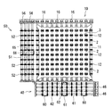
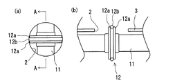
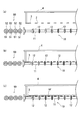
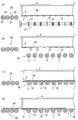
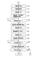
以下、本発明の一実施形態である物品搬送装置について、図1乃至図9に基づいて説明する。本実施形態では、物品搬送装置を、上流側の直進型の搬送装置によって搬送されて来る物品を搬入し、搬送方向を反時計回りに90度旋回した後、下流側の直進型の搬送装置に物品を搬出するために使用する場合について例示する。ここで、図1は本実施形態の物品搬送装置の構成を示す側面図、図2は物品搬送装置の要部の構成を示す平面図、図3は物品搬送装置の要部を示す拡大図、図4乃至図6は物品搬送装置の動作を示す説明図、図7は物品搬送装置の機能的構成を示すブロック図、図8及び図9は物品搬送装置における処理の流れを示すフローチャートである。 Hereinafter, an article conveying apparatus according to an embodiment of the present invention will be described with reference to FIGS. 1 to 9. In the present embodiment, the article transporting device carries in an article transported by the upstream linear transporting device, turns the transporting direction by 90 degrees counterclockwise, and then moves to the downstream straight transporting device. An example of the case of using for carrying out an article will be described. Here, FIG. 1 is a side view showing the configuration of the article transporting apparatus of the present embodiment, FIG. 2 is a plan view showing the configuration of the main part of the article transporting apparatus, and FIG. 3 is an enlarged view showing the main part of the article transporting apparatus. 4 to 6 are explanatory views showing the operation of the article conveying apparatus, FIG. 7 is a block diagram showing the functional configuration of the article conveying apparatus, and FIGS. 8 and 9 are flowcharts showing the flow of processing in the article conveying apparatus.
本実施形態の物品搬送装置1は、図1に示すように、同一の水平面上に略平行に並設された複数の回転軸11、及び、回転軸11と同心に回転する複数の回転体12を有して構成される搬送路10と、回転軸11を回転駆動する回転駆動モータ15と、搬送路10を略鉛直な旋回軸21を中心として所定角度旋回させる旋回駆動モータ25と、円形の孔部2が形成された穿孔プレート3と、穿孔プレート3を挿通位置及び離隔位置に変位させるプレート駆動シリンダ5と、各構成を制御する制御手段9とを主に具備して構成されている。
As shown in FIG. 1, the
更に詳細に説明すると、搬送路10の回転軸11には、夫々に複数の回転体12が所定間隔で取付けられている。この回転体12は、図3(a)及び図3(b)に示すように、夫々一対の環状体12aと、その間に挟持されたOリング12bを有して構成され、物品Wを搬送する際、このOリング12bの部分で物品Wを支持する。このOリング12bは、摩耗等に応じて適宜取替えが可能である。また、搬送する物品の性質や搬送工程で施される処理等に応じた材質、例えば、耐熱性のあるシリコーンゴム、耐薬品性のあるフッ素系ゴム、耐油性のあるニトリルゴム製のもの等を適宜選択することができる。また、夫々の回転軸11は、スプロケット16とチェーン17によって連結され、チェーン17が掛装された回転駆動モータ15の駆動により、同一方向に回転する。なお、回転駆動モータ15、スプロケット16、及びチェーン17が、本発明の回転駆動手段に相当する。
More specifically, a plurality of
そして、回転軸11及び回転駆動モータ15は、旋回テーブル22の側板に固定されることにより旋回テーブル22に支持されている。そして、旋回駆動モータ25の駆動により旋回テーブル22が旋回することによって、搬送路10が旋回する構成とされている。ここで、旋回駆動モータ25には、インデックス27が取付けられている。このインデックス27は、入力軸に与えられた旋回駆動モータ25の等速回転運動を、所定角度の旋回または停止として出力するものであり、インデックス27の出力軸が旋回テーブル22の旋回中心としての旋回軸21となる。この旋回軸21は、旋回テーブル22の略中央に、略鉛直に設けられている。また、インデックス27には、旋回位置を検知するためのインデックスセンサ67が取付けられている。なお、旋回駆動モータ25及びインデックス27が、本発明の旋回手段に相当する。
The rotating
穿孔プレート3は、本実施形態では、搬送路10の上方で鉛直方向に昇降することにより、挿通位置及び離隔位置に変位する構成とされている。すなわち、穿孔プレート3は、側柱を有するプレート支持板4によって上方から支持され、このプレート支持板4は、プレート駆動シリンダ5の駆動によりピストン運動するピストンロッド6の端部に取付けられている。また、このプレート駆動シリンダ5は、物品搬送装置1のケーシング70の天井部から下方に向かって、ピストンロッド6のピストン運動が鉛直方向となるように取付けられている。更に、プレート駆動シリンダ5に設けられた一対のエア挿入孔5aに連通するエア通路(図示しない)には、通路を開閉するプレート駆動シリンダ電磁弁5b(図7参照)が取付けられている。従って、プレート駆動シリンダ電磁弁5bの開閉によりプレート駆動シリンダ5へ圧縮空気を送入することにより、穿孔プレート3が水平状態を維持しつつ昇降する構成とされている。なお、プレート駆動シリンダ5及びピストンロッド6が、本発明のプレート変位手段に相当する。また、穿孔プレート3には、円形の孔部2が、搬送路10における回転体12の配置と対応する位置に穿設されている。従って、穿孔プレート3が搬送路10に向かって下降し、挿通位置にあるときは、図2及び図3(a)に示すように、回転体12が孔部2に臨むこととなる。そして、その状態では、図3(b)に図3(a)のA−A端面図を示したように、孔部2に回転体12が下方から挿通され、穿孔プレート3の上面から回転体12の上部が突出することとなる。
In this embodiment, the
また、本実施形態の物品搬送装置1は、上記構成に加え、図1及び図2に示すように、物品Wを搬送路10に搬入する入口路40と、所定角度旋回した搬送路10から物品Wを搬出する出口路50と、搬送路10を昇降させる駆動シリンダ35と、搬送路10に搬入される物品Wの幅を検出する一対のワーク幅センサ60とを更に具備している。
Further, in addition to the above configuration, the
更に詳細に説明すると、駆動シリンダ35は、ケーシング70の内側面に対して横架された横桁材72に取付けられている。そして、上記のプレート駆動シリンダ5の場合と同様に、エア通路に取付けられた駆動シリンダ電磁弁35b(図7参照)の開閉により、駆動シリンダ35のエア送入孔35aに圧縮空気を送入することにより、ピストンロッド36が上下動する。このピストンロッド36は、昇降テーブル32の下面に取付けられており、この昇降テーブル32には、旋回テーブル22、旋回駆動モータ25、及びインデックス27が載置されている。更に、旋回テーブル22は、上記のように、搬送路10や回転駆動モータ15等を支持している。すなわち、駆動シリンダ35の駆動により、搬送路10が昇降可能な構成とされている。なお、駆動シリンダ35及びピストンロッド36が、本発明の昇降手段に相当する。また、昇降テーブル32の下面には一対のガイドシャフト37が取付けられ、横桁材72には、このガイドシャフト37を鉛直方向に挿通可能なガイドスリーブ38が一対設けられている。すなわち、昇降テーブル32が昇降する際に、ガイドシャフト37がガイドスリーブ38を挿通した状態で上下動することにより、昇降テーブル32の鉛直方向の昇降が安定したものとなる。なお、図示しないが、同様のガイドスリーブがケーシング70の天井部にも設けられ、プレート支持板4の上面に取付けられたガイドシャフトがこれを挿通して上下動することにより、上記のプレート支持板4を安定して昇降させる構成となっている。
More specifically, the
入口路40は、搬送路10と同様に、同一の水平面上に略平行に並設された複数の第二回転軸41、及び、第二回転軸41と同心に回転する複数の第二回転体42を有して構成され、第二回転軸41は第二駆動モータ45(図7参照)、スプロケット46、及びチェーン(図示しない)によって連動して回転駆動される。また、同様に出口路50も、同一の水平面上に略平行に並設された複数の第三回転軸51、及び、第三回転軸51と同心に回転する複数の第三回転体52を有して構成され、第三回転軸51は第三駆動モータ55、スプロケット56、及びチェーン57によって連動して回転駆動される。この出口路50は、入口路40との間に搬送路10を介在させ、搬送方向が入口路40に対して反時計回りに90度旋回した方向となるように設けられている。また、入口路40及び出口路50の夫々の回転軸41,51は、ケーシング70の内側面に固定され、搬送面が同一の高さとなるように設定されている。なお、第二駆動モータ45、スプロケット46、及びチェーンが、本発明の入口路駆動手段に相当し、第三駆動モータ55、スプロケット56、及びチェーン57が、本発明の出口路駆動手段に相当する。
Similarly to the
入口路40には、搬送される物品Wが最初に到達する最前の回転軸41に、物品の幅を検出する一対のワーク幅センサ60が取付けられている。更に、入口路40には、最前及び最後の回転軸41に、物品Wの通過を検知する入口第一センサ61及び入口第二センサ62が夫々取付けられている。また、出口路50においても、最前及び最後の回転軸51に、物品Wの通過を検知する出口第一センサ65及び出口第二センサ66が夫々取付けられている。
A pair of
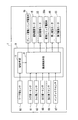
次に、本実施形態における機能的構成について、図7に基づいて説明する。ここで、物品搬送装置1の機能的構成の主たる構成は、演算及び制御を行う中央処理装置(CPU)や、ROM及びRAM等の記憶装置を備えた制御手段9である。そして、制御手段9は、ワーク幅検出センサ60の出力に基づいて、維持搬送及び旋回搬送に切替える切替手段7と、切替手段7による切替に基づいて、搬送路10、入口路40、及び出口路50による搬送動作を制御する搬送制御手段8を備えている。そして、この搬送制御手段8は、入口第一センサ61、入口第二センサ62、出口第一センサ65、出口第二センサ66、及びインデックス67センサからの出力に基づいて、プレート駆動シリンダ5の電磁弁5bの開閉、回転駆動モータ15、旋回駆動モータ25、第二駆動モータ45、第三駆動モータ55の回転及び停止、及び駆動シリンダ電磁弁35bの開閉の制御を行う。
Next, a functional configuration in the present embodiment will be described with reference to FIG. Here, the main configuration of the functional configuration of the
次に、本実施例の物品搬送装置1の動作の概略を図4乃至図6に基づいて説明する。まず、搬入方向に対する物品Wの向きを維持したまま搬送方向を旋回させる維持搬送を行う場合、穿孔プレート3は挿通位置に置かれる。従って、図4(a)に示すように穿孔プレート3が離隔位置にある場合は、入口路40から搬送路10への物品Wの搬入に先立ち、図4(b)に示すように、穿孔プレート3を下降させて挿通位置に変位させる。これにより、回転体12が穿孔プレート3の孔部2に下方から挿通される。その後、入口路40から搬送路10に物品Wが搬入されると、図4(c)に示すように、穿孔プレート3の上面から一部突出した回転体12によって、物品Wが支持され、搬送される。なお、図4における紙面の手前から奥行き方向が、入口路40から搬送路10への搬送方向に相当する。この状態で、穿孔プレート3はその位置のまま搬送路10を下降させると、搬送路10と穿孔プレート3とが離隔し、図5(d)に示すように、物品Wは穿孔プレート3の上面に載置される。従って、図5(e)に示すように、搬送路10を90度旋回させる際には、物品Wは搬送路10から外された状態にあり、物品W自体は旋回しない。その後、旋回を終えた搬送路10を上昇させると、図5(f)に示すように、再び、穿孔プレート3の上面から一部突出した回転体12によって物品Wが支持される。そして、搬送路10及び出口路50の夫々の回転体12、52を回転させることにより、図5(g)に示すように、物品Wが搬送路10から出口路50に搬出される。
Next, the outline of the operation of the
一方、搬送方向と共に物品W自体も旋回させる旋回搬送の際は、穿孔プレート3は使用しない。すなわち、図6(a)に示すように、穿孔プレート3は離隔位置に位置させたまま、入口路40から搬送路10に物品Wを搬入する。その後、図6(b)及び図6(c)に示すように、搬送路10を下降させて旋回させると、物品Wも回転体12に支持されたまま、搬送路10と共に下降し旋回する。その後、図6(d)に示すように、搬送路10を上昇させ、物品Wを搬送路10から出口路50に搬出させる。
On the other hand, the perforating
次に、本実施形態の物品搬送装置1における処理の流れについて、主に図7乃至図9に基づいて説明する。まず、物品搬送装置1を稼働させた後、上流側の搬送装置によって搬送された物品Wが入口路40との境界に達すると、入口第一センサ61によって物品Wが検知され(ステップS1においてYES)、搬入許可信号が送出されているか否かが確認される(ステップS2)。この搬入許可信号は、前に搬送された物品Wの搬送が完了或いは所定の段階まで進行し、物品搬送装置1内に次の物品Wを搬入可能な状態となったときに送出される信号である。搬入許可信号が送出されていない場合は(ステップS2においてNO)、送出されるまで待機する。一方、搬入許可信号が既に送出されている場合は(ステップS2においてYES)、この信号を消去し(ステップS3)、入口路40の第二回転軸41を回転させて、上流側装置から入口路40への物品Wの搬入を開始する(ステップS4)。このとき、第二回転軸41の回転速度を、上流側装置の搬送速度に合致させることができる。この第二回転軸41の回転により、物品Wが入口路40上に進入すると、一対のワーク幅センサ60によって物品Wの幅が検出される。本実施形態では、物品Wの幅によって維持搬送と旋回搬送とを切替えることとし、物品Wの幅が基準値より小のときは維持搬送を、基準値より大のときは旋回搬送を行う設定として例示する。ワーク幅センサ60によりワーク幅が検出されると(ステップS5においてYES)、基準値との比較が行われる(ステップS6)。物品Wの幅が基準値より小のときは(ステップS6においてYES)、穿孔プレート3が挿通位置にあるか否かが確認され(ステップS7)、挿通位置にないときは(ステップS7においてNO)、プレート駆動シリンダ5を駆動させて穿孔プレート3を下降させる(ステップS8)。一方、物品Wの幅が基準値より大のときは(ステップS6においてNO)、穿孔プレート3が離隔位置にあるか否かが確認され(ステップS9)、離隔位置にないときは(ステップS9においてNO)、穿孔プレート3を上昇させる(ステップS10)。
Next, the flow of processing in the
その後、維持搬送の場合は穿孔プレート3が挿通位置にあり、旋回搬送の場合は穿孔プレート3が離隔位置ある状態で、搬送路10の回転軸11を回転させ、物品Wを入口路40から搬送路10上に搬入させる(ステップS11)。このとき、入口路40の第二回転軸41と搬送路10の回転軸11との回転速度を一致させるように制御することができる。そして、入口路40を物品Wが通過し終えるまで、すなわち、入口第二センサ62によって物品Wの後端が検知されないうちは(ステップS12においてNO)、入口路40及び搬送路10による搬送が行われる。
After that, in the case of maintenance conveyance, the
入口第二センサ62によって物品Wの後端が検知されると(ステップS12においてYES)、入口路40の回転軸41が停止される(ステップS13)。また、搬送路10の回転軸11を停止させるタイミングが算出される(ステップS14)。すなわち、入口第二センサ62によって物品Wの前端が検知されてから後端が検知されるまでのモータの回転を、パルス計測することによって物品Wの長さを算出し、物品Wが搬送路10の中央位置より更にその長さの1/2に相当する距離だけ移動するまで、回転軸11を回転させてから停止させるよう、そのタイミングが算出される。この際、停止信号が出されてから実際に回転軸11が停止するまでの誤差が考慮される。この算出結果に基づいて回転軸11が停止されると(ステップS15)、物品Wは搬送路10の中央で静止する。なお、このように、物品Wを搬送路10の中央に位置させることは、維持搬送の場合には、旋回搬送の場合と比べてより重要である。なぜなら、旋回搬送の場合は、搬送路10に搬入された物品Wが中央位置より行き過ぎたり、中央位置より手前で停止したりしても、下流側の搬送路上での幅方向(搬送方向に直交する方向)における位置は、上流側の搬送路上における位置と変わることがない。これに対して、維持搬送の場合は、仮に上流側では物品Wが搬送路の中心線上を搬送されて来たとしても、搬送路10内で中央位置からずれてしまうと、下流側では搬送路の右端或いは左端に偏って位置してしまい、搬送が不安定となるおそれがあるからである。
When the rear end of article W is detected by inlet second sensor 62 (YES in step S12),
上記のように、物品Wが中央に位置する状態で搬送路10の回転軸11を停止させた後、旋回の際の入口路40及び出口路50との干渉を回避するため、搬送路10を下降させる(ステップS16)。このとき、維持搬送であれば物品Wは穿孔プレート3上に載置され、旋回搬送であれば物品Wは搬送路10上に載置されている。そして、搬送路10を反時計回りに90度旋回させ(ステップS17)、更に出口路50と同じ高さまで上昇させる(ステップS18)。これにより、維持搬送であれば、物品Wは孔部2に挿通された回転体12によって再び支持されることとなる。
As described above, after the
次に、搬送路10及び出口路50の夫々の回転軸11,51を回転させることにより、搬送路10から出口路50に物品Wを搬出させる(ステップS19)。すなわち、維持搬送された物品Wは搬入方向に対する向きを維持したまま、反時計回りに90度の方向に搬送される。一方、旋回搬送された物品Wは、搬送方向と共にその向きが反時計回りに90度旋回されて搬送される。その後、搬送路10から物品Wが搬出されるまで、すなわち、出口第一センサ65によって物品Wの後端が検知されないうちは(ステップS20においてNO)、搬送路10及び出口路50の回転軸11,51の回転が継続される。出口第一センサ65によって物品Wの後端が検知されると(ステップS20においてYES)、搬送路10の回転軸11を停止させ(ステップS21)、搬送路10を下降させ(ステップS22)、元の位置まで戻すために、時計回りに90度旋回させ(ステップS23)、更に入口路40と同じ高さまで上昇させる(ステップS24)。これにより、次の物品Wを搬送路10に搬入可能な状態となるため、搬入許可信号が送出される(ステップS25)。また、物品Wが出口路50を通過し終えたか否か、すなわち出口第二センサ66が物品Wの後端を検知したかが確認され、通過していれば(ステップS26においてYES)、出口路50の回転軸51を停止させる(ステップS27)。その後、一連の搬送を終了させる停止命令がなければ(ステップS28においてNO)、ステップS1に戻り、上記の処理の流れにより物品Wの搬送が継続される。一方、手動操作等により停止命令を受けたときは(ステップS28においてYES)、これに応じて搬送動作を終了する。
Next, the articles W are transported from the
上記の処理の流れは例示であり、入口路40、搬送路10、及び出口路50の回転軸41,11,51の回転や停止、搬送路10の旋回や昇降等の各動作を、別のタイミングに制御することもできる。例えば、本実施形態では、搬送路10が旋回する際に下降するために、搬送路10と入口路40、出口路10との境界上に物品Wの一部が存在することが許容される。そのため、例えば、搬送路10から物品Wが完全に搬出されなくても、物品Wが所定の長さだけ通過したことが出口第一センサによって検出された段階で、搬送路10が下降するように制御することもできる。また、搬送路10が元の位置に戻るための旋回及び上昇を終える前に搬入許可信号が送出される設定とし、次に搬送路に搬入されるべき物品を、搬送路10上にある程度進入させるよう制御することもできる。そして、このような処理の流れとすることにより、搬送効率を高めることができる。
The above processing flow is an example, and each operation such as rotation and stop of the
上記に説明したように、本実施形態の物品搬送装置1によれば、単一の装置でありながら、物品Wの搬入方向に対する向きを変えずに搬送方向のみを旋回させる維持搬送、及び、搬送方向と共に物品Wを旋回させる旋回搬送を、共に行うことが可能となる。
As described above, according to the
また、維持搬送すべき物品Wと旋回搬送すべき物品Wとを同一ラインに混在させて搬送しても、ワーク幅センサ60による物品Wの検出に基づいて、自動的に維持搬送及び旋回搬送の何れかに切替えて搬送することができる。
Further, even if the article W to be maintained and the article W to be swiveled are mixed and conveyed on the same line, the maintenance and swirl conveyance are automatically performed based on the detection of the article W by the
更に、搬送方向の異なる入口路40及び出口路50を具備することにより、上流側の搬送装置から搬送されて来る物品Wを搬送路10に搬入し、搬送方向を旋回させた後に、下流側の搬送装置に搬出するという一連の動作のタイミングを合わせることが容易となり、物品Wを円滑に搬送することが可能となる。
Furthermore, by providing the
また、搬送路10を旋回させる際に下降させる構成とすることにより、搬送路10が入口路40及び出口路50と干渉することを回避することができる。更に、搬送路10が下降して旋回している間に、次に搬送路10に搬入されるべき物品Wを、入口路40からある程度搬送路10上に進入させ、或いは、搬送路10から出口路50に物品Wが完全に搬出される前に、搬送路10を旋回させる等の設定が可能となるため、物品Wの搬送効率の向上を図ることできる。加えて、維持搬送の際、挿通位置にある穿孔プレート3を変位させなくても、搬送路10が下降することによって、搬送路10と穿孔プレート3を離隔させることができるため、少ない動作で効率良く維持搬送を行うことが可能となる。
Moreover, it can avoid that the
以上、本発明について好適な実施形態を挙げて説明したが、本発明は上記の実施形態に限定されるものではなく、以下に示すように、本発明の要旨を逸脱しない範囲において、種々の改良及び設計の変更が可能である。 The present invention has been described with reference to the preferred embodiments. However, the present invention is not limited to the above-described embodiments, and various improvements can be made without departing from the scope of the present invention as described below. And design changes are possible.
例えば、本実施形態では、搬送方向を反時計回りに90度旋回させる場合を例示したが、旋回させる角度はこれに限定されない。例えば、旋回角度を180度とすることにより、同一ラインで搬送される物品について、ある物品はその向きを反転させ、ある物品は向きを維持したまま、共に直進搬送することが可能となる。また、本実施形態では、入口路及び出口路を夫々一つずつ備える場合を例示したが、複数備える構成とすることもできる。例えば、入口路に対して時計回りに90度の出口路と、反時計回りに90度の出口路を具備する構成とし、夫々の方向に維持搬送または旋回搬送させることができる。また、入口路及び出口路を共に複数備えるものとし、物品の搬送工程におけるターミナル的な装置として使用することもできる。 For example, in this embodiment, the case where the conveyance direction is turned 90 degrees counterclockwise is illustrated, but the turning angle is not limited to this. For example, by setting the turning angle to 180 degrees, it is possible to reverse the direction of an article that is conveyed on the same line, and to carry the article straightly while maintaining the orientation. Further, in the present embodiment, the case where one entrance path and one exit path are provided is illustrated, but a configuration including a plurality of entrance paths and exit paths may be employed. For example, a 90-degree exit path clockwise with respect to the entrance path and a 90-degree exit path counterclockwise can be provided, and can be maintained or swiveled in each direction. In addition, it is possible to provide a plurality of inlet passages and outlet passages, and it can be used as a terminal-like device in the article transporting process.
また、本実施形態では、維持搬送及び旋回搬送の何れを行う物品であるかを、物品の幅で判断する場合を例示したが、判断の対象は物品のサイズには限定されない。例えば、物品の重さ、形状、色、物品に施された識別マーク等を判断材料として検出するものとすることができる。 Further, in the present embodiment, the case where it is determined by the width of the article whether the article is to be maintained or swiveled is exemplified, but the determination target is not limited to the size of the article. For example, the weight, shape, color, and identification mark on the article can be detected as the judgment material.
また、本実施例では、穿孔プレートが昇降することにより挿通位置と離隔位置に変位する場合を例示したが、かかる構成に限定されるものではない。例えば、挿通位置にある穿孔プレートが、水平方向にスライドすることにより離隔位置に変位する構成とすることができる。或いは、本実施形態と同様に、搬送路が下降して旋回する構成を採用した場合は、穿孔プレートは、物品を載置した状態では変位する必要がなく、物品を載置することがない旋回搬送のときのみ変位して離隔位置を取ればよいため、穿孔プレートの一辺に沿った水平な軸回りに回動することにより、離隔位置に変位する構成とすることもできる。 In the present embodiment, the case where the perforated plate is moved up and down to be displaced between the insertion position and the separation position is illustrated, but the present invention is not limited to this configuration. For example, the perforated plate in the insertion position can be displaced to the separation position by sliding in the horizontal direction. Alternatively, as in the present embodiment, when a configuration is adopted in which the conveyance path is lowered and swiveled, the perforation plate does not need to be displaced in a state where the article is placed, and does not place the article. Since it is only necessary to displace and take a separation position only at the time of conveyance, it can also be configured to be displaced to the separation position by rotating around a horizontal axis along one side of the perforation plate.
1 物品搬送装置
2 孔部
3 穿孔プレート
5 プレート駆動シリンダ(プレート変位手段)
6 ピストンロッド(プレート変位手段)
9 制御手段
10 搬送路
11 回転軸
12 回転体
12a 環状体(回転体)
12b Oリング(回転体)
15 回転駆動モータ(回転駆動手段)
16 スプロケット(回転駆動手段)
17 チェーン(回転駆動手段)
21 旋回軸
25 旋回駆動モータ(旋回手段)
27 インデックス(旋回手段)
35 駆動シリンダ(昇降手段)
36 ピストンロッド(昇降手段)
40 入口路
45 第二駆動モータ(入口路駆動手段)
46 スプロケット(入口路駆動手段)
50 出口路
55 第三駆動モータ(出口路駆動手段)
56 スプロケット(出口路駆動手段)
57 チェーン(出口路駆動手段)
60 ワーク幅センサ(検出手段)
W 物品
DESCRIPTION OF
6 Piston rod (plate displacement means)
9 Control means 10
12b O-ring (Rotating body)
15 Rotation drive motor (Rotation drive means)
16 Sprocket (Rotary drive means)
17 Chain (Rotary drive means)
21 Rotating
27 Index (turning means)
35 Drive cylinder (lifting means)
36 Piston rod (lifting means)
40
46 Sprocket (inlet path drive means)
50
56 Sprocket (exit path drive means)
57 Chain (exit path drive means)
60 Work width sensor (detection means)
W goods
Claims (3)
前記回転軸を回転駆動する回転駆動手段と、
前記搬送路を略鉛直な旋回軸を中心として所定角度旋回させる旋回手段と、
前記回転体の一部を挿通可能な孔部が形成され、該孔部以外の部分で物品を載置可能な穿孔プレートと、
該穿孔プレートを、前記孔部に前記回転体の一部を下方から挿通させる挿通位置、及び前記搬送路から離隔した離隔位置に変位させるプレート変位手段と、
前記物品の搬入方向に対する向きを維持して搬送方向のみを旋回させる維持搬送、及び搬送方向と共に前記物品を旋回させる旋回搬送の何れかに切替えると共に、
前記回転駆動手段、前記旋回手段、及び前記プレート変位手段を制御し、
前記維持搬送の場合は、前記穿孔プレートを挿通位置に変位させ、前記孔部に一部挿通された前記回転体の回転によって、前記物品を前記搬送路外から前記搬送路上に搬入させ、前記搬送路及び前記穿孔プレートを離隔させ、前記穿孔プレートの上面に前記物品が載置された状態で前記搬送路を旋回させ、前記孔部に前記回転体の一部を下方から再度挿通させ、前記回転体の回転によって前記物品を前記搬送路外へ搬送させ、
前記旋回搬送の場合は、前記穿孔プレートを離隔位置に変位させ、前記回転体の回転によって前記物品を前記搬送路外から前記搬送路上に搬入させ、前記物品が載置された状態で前記搬送路を旋回させ、前記回転体の回転によって前記物品を前記搬送路外へ搬出させる制御手段と
を具備することを特徴とする物品搬送装置。 A plurality of rotating shafts arranged in parallel on the same horizontal plane, and a plurality of rotating bodies that protrude from the peripheral surface of the rotating shaft and rotate concentrically with the rotating shaft. Road,
A rotation drive means for rotating the rotation shaft;
Turning means for turning the transport path by a predetermined angle around a substantially vertical turning axis;
A hole part through which a part of the rotating body can be inserted is formed, and a perforated plate on which an article can be placed at a part other than the hole part;
A plate displacing means for displacing the perforated plate to the insertion position where a part of the rotating body is inserted into the hole portion from below and the separation position separated from the transport path;
While maintaining the direction with respect to the carry-in direction of the article, switching to one of maintenance conveyance that turns only the conveyance direction, and turning conveyance that turns the article together with the conveyance direction,
Controlling the rotation driving means, the turning means, and the plate displacement means;
In the case of the maintenance conveyance, the perforation plate is displaced to the insertion position, and the article is carried from the outside of the conveyance path onto the conveyance path by the rotation of the rotating body partially inserted through the hole, and the conveyance The path and the perforation plate are separated from each other, the conveyance path is swung in a state where the article is placed on the upper surface of the perforation plate, and a part of the rotating body is reinserted into the hole portion from below, and the rotation is performed. Transporting the article out of the transport path by rotating the body,
In the case of the swivel conveyance, the perforation plate is displaced to a separation position, and the article is carried from the outside of the conveyance path onto the conveyance path by the rotation of the rotating body, and the conveyance path is in a state where the article is placed. And a control means for carrying out the article out of the conveyance path by the rotation of the rotating body.
前記物品を前記搬送路に搬入する入口路と、
所定角度旋回した前記搬送路から前記物品を搬出する出口路と、
前記入口路を駆動する入口路駆動手段と、
前記出口路を駆動する出口路駆動手段と、
前記搬送路を昇降させる昇降手段と
を更に具備し、
前記制御手段は、
前記検出手段の検出に基づいて前記維持搬送及び前記旋回搬送の何れかに切替え、
前記入口路駆動手段及び前記出口路駆動手段を制御して、前記入口路及び前記出口路を前記搬送路と協働させると共に、
前記昇降手段を制御し、旋回の際は前記搬送路を前記入口路及び前記出口路の何れの高さとも異なる高さまで下降させ、前記物品の搬入及び搬出の際は、夫々前記入口路及び前記出口路と同じ高さまで前記搬送路を上昇させる
ことを特徴とする請求項1に記載の物品搬送装置。 Detecting means for detecting the type of the article carried into the transport path;
An entrance path for carrying the article into the transport path;
An exit path for unloading the article from the transport path rotated by a predetermined angle;
An inlet path driving means for driving the inlet path;
Exit path driving means for driving the exit path;
Elevating means for elevating and lowering the conveyance path;
The control means includes
Based on the detection of the detection means, switching to either the maintenance transport and the swivel transport,
Controlling the inlet path driving means and the outlet path driving means so that the inlet path and the outlet path cooperate with the transport path;
Controlling the elevating means, and lowering the conveying path to a height different from any of the inlet path and the outlet path when turning, and when carrying the article in and out, respectively the inlet path and the The article conveying apparatus according to claim 1, wherein the conveying path is raised to the same height as the exit path.
Priority Applications (1)
| Application Number | Priority Date | Filing Date | Title |
|---|---|---|---|
| JP2005254377A JP4633581B2 (en) | 2005-09-02 | 2005-09-02 | Article conveying device |
Applications Claiming Priority (1)
| Application Number | Priority Date | Filing Date | Title |
|---|---|---|---|
| JP2005254377A JP4633581B2 (en) | 2005-09-02 | 2005-09-02 | Article conveying device |
Publications (2)
| Publication Number | Publication Date |
|---|---|
| JP2007062995A true JP2007062995A (en) | 2007-03-15 |
| JP4633581B2 JP4633581B2 (en) | 2011-02-16 |
Family
ID=37925614
Family Applications (1)
| Application Number | Title | Priority Date | Filing Date |
|---|---|---|---|
| JP2005254377A Expired - Lifetime JP4633581B2 (en) | 2005-09-02 | 2005-09-02 | Article conveying device |
Country Status (1)
| Country | Link |
|---|---|
| JP (1) | JP4633581B2 (en) |
Cited By (5)
| Publication number | Priority date | Publication date | Assignee | Title |
|---|---|---|---|---|
| JP2009083995A (en) * | 2007-09-28 | 2009-04-23 | Toyo Kiki Kogyo Kk | Roller member for conveying device and conveying device |
| CN102211712A (en) * | 2010-04-12 | 2011-10-12 | 株式会社大福 | Conveyance device and conveyance method |
| CN103303659A (en) * | 2013-06-18 | 2013-09-18 | 衡水英利新能源有限公司 | Transmission component reforming device |
| CN105109979A (en) * | 2015-08-26 | 2015-12-02 | 卓达新材料科技集团有限公司 | Automatic plate turning and conveying device |
| CN122166495A (en) * | 2026-05-11 | 2026-06-09 | 西安航天化学动力有限公司 | Lateral locking devices, methods, and conveying systems that accommodate operating containers of different sizes |
Families Citing this family (1)
| Publication number | Priority date | Publication date | Assignee | Title |
|---|---|---|---|---|
| CN109879021B (en) * | 2019-03-29 | 2021-03-16 | 阳兴造机(昆山)有限公司 | A tooling plate overturning device and its working method |
Citations (3)
| Publication number | Priority date | Publication date | Assignee | Title |
|---|---|---|---|---|
| JPS6259640U (en) * | 1985-10-02 | 1987-04-13 | ||
| JPH051731U (en) * | 1991-06-26 | 1993-01-14 | レンゴー株式会社 | Turntable equipment |
| JPH061334U (en) * | 1992-06-04 | 1994-01-11 | 株式会社内田製作所 | Article orientation changer |
-
2005
- 2005-09-02 JP JP2005254377A patent/JP4633581B2/en not_active Expired - Lifetime
Patent Citations (3)
| Publication number | Priority date | Publication date | Assignee | Title |
|---|---|---|---|---|
| JPS6259640U (en) * | 1985-10-02 | 1987-04-13 | ||
| JPH051731U (en) * | 1991-06-26 | 1993-01-14 | レンゴー株式会社 | Turntable equipment |
| JPH061334U (en) * | 1992-06-04 | 1994-01-11 | 株式会社内田製作所 | Article orientation changer |
Cited By (6)
| Publication number | Priority date | Publication date | Assignee | Title |
|---|---|---|---|---|
| JP2009083995A (en) * | 2007-09-28 | 2009-04-23 | Toyo Kiki Kogyo Kk | Roller member for conveying device and conveying device |
| CN102211712A (en) * | 2010-04-12 | 2011-10-12 | 株式会社大福 | Conveyance device and conveyance method |
| KR101331106B1 (en) * | 2010-04-12 | 2013-11-19 | 가부시키가이샤 다이후쿠 | Transport device and transport method |
| CN103303659A (en) * | 2013-06-18 | 2013-09-18 | 衡水英利新能源有限公司 | Transmission component reforming device |
| CN105109979A (en) * | 2015-08-26 | 2015-12-02 | 卓达新材料科技集团有限公司 | Automatic plate turning and conveying device |
| CN122166495A (en) * | 2026-05-11 | 2026-06-09 | 西安航天化学动力有限公司 | Lateral locking devices, methods, and conveying systems that accommodate operating containers of different sizes |
Also Published As
| Publication number | Publication date |
|---|---|
| JP4633581B2 (en) | 2011-02-16 |
Similar Documents
| Publication | Publication Date | Title |
|---|---|---|
| KR101787356B1 (en) | Transfer system | |
| US4631812A (en) | Programmable substrate transport for electronic assembly | |
| KR101732449B1 (en) | Conveying system | |
| JP4633581B2 (en) | Article conveying device | |
| JP4349222B2 (en) | Laser marking device, laser marking method, and processing method in laser marking device | |
| JPH1148046A (en) | A method of continuously processing a continuous workpiece along a production line | |
| US20190039839A1 (en) | Method and apparatus for transport of a glass substrate | |
| WO2005055312A1 (en) | Substrate positioning system | |
| WO2006137249A1 (en) | Work transfer system | |
| JP5149074B2 (en) | Paper transport device and paper transport system | |
| JP2009081364A (en) | Component mounting system and component mounting method | |
| JP2007530296A (en) | Panel cutter for quilt fabric | |
| JP2007277004A (en) | Article positioning device | |
| TWI556880B (en) | Sorting machine | |
| JP6421323B2 (en) | Component mounting equipment | |
| JP2018012590A (en) | Conveyor with alternative cutting mechanism | |
| JP5012466B2 (en) | Paper sheet processing equipment | |
| CN112827852A (en) | Metal parts automatic transport and detection device and its operation method | |
| JP2007308264A (en) | Direction changing device | |
| WO2009113160A1 (en) | Substrate conveyor and substrate conveyance method | |
| US6702280B2 (en) | Apparatus and process for transporting sheet-shaped print materials | |
| JP4827573B2 (en) | A substrate positioning method, a substrate positioning device, and a plasma display back plate manufacturing apparatus. | |
| JP2009128102A (en) | Rod-shaped article diameter measuring system and its measuring method | |
| KR101238497B1 (en) | Apparatus for cutting circuit board | |
| JP2016520435A (en) | Surface processing equipment |
Legal Events
| Date | Code | Title | Description |
|---|---|---|---|
| A621 | Written request for application examination |
Free format text: JAPANESE INTERMEDIATE CODE: A621 Effective date: 20070502 |
|
| A977 | Report on retrieval |
Free format text: JAPANESE INTERMEDIATE CODE: A971007 Effective date: 20100210 |
|
| A131 | Notification of reasons for refusal |
Free format text: JAPANESE INTERMEDIATE CODE: A131 Effective date: 20100223 |
|
| A521 | Request for written amendment filed |
Free format text: JAPANESE INTERMEDIATE CODE: A523 Effective date: 20100421 |
|
| TRDD | Decision of grant or rejection written | ||
| A01 | Written decision to grant a patent or to grant a registration (utility model) |
Free format text: JAPANESE INTERMEDIATE CODE: A01 Effective date: 20101109 |
|
| A01 | Written decision to grant a patent or to grant a registration (utility model) |
Free format text: JAPANESE INTERMEDIATE CODE: A01 |
|
| A61 | First payment of annual fees (during grant procedure) |
Free format text: JAPANESE INTERMEDIATE CODE: A61 Effective date: 20101117 |
|
| R150 | Certificate of patent or registration of utility model |
Ref document number: 4633581 Country of ref document: JP Free format text: JAPANESE INTERMEDIATE CODE: R150 Free format text: JAPANESE INTERMEDIATE CODE: R150 |
|
| FPAY | Renewal fee payment (event date is renewal date of database) |
Free format text: PAYMENT UNTIL: 20131126 Year of fee payment: 3 |
|
| R250 | Receipt of annual fees |
Free format text: JAPANESE INTERMEDIATE CODE: R250 |
|
| R250 | Receipt of annual fees |
Free format text: JAPANESE INTERMEDIATE CODE: R250 |
|
| S531 | Written request for registration of change of domicile |
Free format text: JAPANESE INTERMEDIATE CODE: R313531 |
|
| R350 | Written notification of registration of transfer |
Free format text: JAPANESE INTERMEDIATE CODE: R350 |
|
| R250 | Receipt of annual fees |
Free format text: JAPANESE INTERMEDIATE CODE: R250 |
|
| R250 | Receipt of annual fees |
Free format text: JAPANESE INTERMEDIATE CODE: R250 |
|
| S531 | Written request for registration of change of domicile |
Free format text: JAPANESE INTERMEDIATE CODE: R313531 |
|
| R350 | Written notification of registration of transfer |
Free format text: JAPANESE INTERMEDIATE CODE: R350 |
|
| EXPY | Cancellation because of completion of term |