JP2007100331A - Rain gutter water collection basin - Google Patents
Rain gutter water collection basin Download PDFInfo
- Publication number
- JP2007100331A JP2007100331A JP2005289579A JP2005289579A JP2007100331A JP 2007100331 A JP2007100331 A JP 2007100331A JP 2005289579 A JP2005289579 A JP 2005289579A JP 2005289579 A JP2005289579 A JP 2005289579A JP 2007100331 A JP2007100331 A JP 2007100331A
- Authority
- JP
- Japan
- Prior art keywords
- lid
- rain gutter
- main body
- piece
- gutter water
- Prior art date
- Legal status (The legal status is an assumption and is not a legal conclusion. Google has not performed a legal analysis and makes no representation as to the accuracy of the status listed.)
- Pending
Links
- XLYOFNOQVPJJNP-UHFFFAOYSA-N water Substances O XLYOFNOQVPJJNP-UHFFFAOYSA-N 0.000 title claims abstract description 12
- 230000037431 insertion Effects 0.000 claims abstract description 19
- 238000003780 insertion Methods 0.000 claims abstract description 19
- 230000000903 blocking effect Effects 0.000 abstract 1
- 238000010276 construction Methods 0.000 description 9
- 229920003002 synthetic resin Polymers 0.000 description 2
- 239000000057 synthetic resin Substances 0.000 description 2
- 241000277269 Oncorhynchus masou Species 0.000 description 1
- 238000005452 bending Methods 0.000 description 1
- 238000001746 injection moulding Methods 0.000 description 1
- 238000004080 punching Methods 0.000 description 1
Images




Landscapes
- Sewage (AREA)
Abstract
Description
本願発明は、上方へ開口した器状のます本体と、このます本体の上方開口を塞ぐ蓋体とを備え、蓋体に対します本体が下方から係止して取り付けられる雨樋集水ますに関するものである。 The invention of the present application relates to a rain gutter collecting device that has a vessel-shaped main body that opens upward and a lid that closes the upper opening of the main body. Is.
従来から、実開平5−62617号公報(特許文献1)に示されるように、上方へ開口して底部に落とし口が形成された器状のます本体と、ます本体の上方開口を塞ぐ板状で中程に排水管挿入口が形成された蓋体と、を備え、蓋体に対します本体が下方から係止して取り付けられる雨樋集水ますは知られている。この場合、蓋体の排水管挿入口の周囲に天井面取付用の取付孔が配設されており、この取付孔に挿通されるビスにて蓋体は玄関ポーチ屋根の下面や軒天井面等の天井面に固定され、そして、同蓋体に対します本体が下方から係止して取り付けられる。 Conventionally, as shown in Japanese Utility Model Laid-Open No. 5-62617 (Patent Document 1), a bowl-shaped main body that opens upward and has a drop opening formed at the bottom, and a plate shape that closes the upper opening of the main body. And a lid body in which a drainage pipe insertion opening is formed in the middle, and a rain gutter collecting masquer that is attached to the lid body by being locked from below is known. In this case, a mounting hole for mounting the ceiling surface is provided around the drainage pipe insertion port of the lid, and the lid is screwed through the mounting hole so that the lid is the lower surface of the entrance porch roof, the eaves ceiling surface, etc. The main body is fixed to the lid from below and attached to the lid.
しかしながら、上記の雨樋集水ますは、建物の外壁面等の壁面に取り付けることができないものであった。また、特開平9−25691号公報(特許文献2)や特開平10−46765号公報(特許文献3)等に示される雨樋集水ますは、建物の外壁面等の壁面に取り付けられるものであって、玄関ポーチ屋根の下面や軒天井面等の天井面には取り付けることができないものであった。このように、従来にあっては、天井面に取り付けられる雨樋集水ますと壁面に取り付けられる雨樋集水ますとは全く別異のものであり、共用し得ないものであった。
本願発明は、上記背景技術に鑑みてなされたものであり、その課題は、天井面、壁面のいずれにも適合させて取り付けることができる使い勝手の良い雨樋集水ますを提供することである。 This invention is made | formed in view of the said background art, The subject is providing the easy-to-use rain gutter water collection system which can be fitted and attached to both a ceiling surface and a wall surface.
上記課題を解決するために、本願発明の雨樋集水ますは、上方へ開口して底部に落とし口が形成された器状のます本体と、ます本体の上方開口を塞ぐ板状で中程に排水管挿入口が形成された蓋体と、を備え、蓋体に対します本体が下方から係止して取り付けられる雨樋集水ますであり、蓋体の排水管挿入口の周囲に天井面取付用の上方取付孔を配設し、同蓋体の後縁に壁面取付用の側方取付孔を有する固定片を垂設してなる。 In order to solve the above-mentioned problems, the rain gutter collecting basin of the present invention has a bowl-shaped main body that opens upward and has a drop mouth formed at the bottom, and a plate-like middle that closes the upper opening of the main body. And a lid body having a drain pipe insertion opening formed therein, and a rain gutter water collecting body attached to the lid body by locking from below, and a ceiling around the drain pipe insertion opening of the lid body. An upper mounting hole for surface mounting is provided, and a fixing piece having side mounting holes for wall mounting is suspended from the rear edge of the lid.
本願発明の雨樋集水ますにおいては、蓋体の排水管挿入口の周囲に天井面取付用の上方取付孔が配設されているので、この上方取付孔に挿通されるビス等の固定具にて蓋体を玄関ポーチ屋根の下面や軒天井面等の天井面に安定させて固定することができ、また、同蓋体の後縁に壁面取付用の側方取付孔を有する固定片が垂設されているので、この側方取付孔に挿通されるビス等の固定具にて蓋体を建物の外壁面等の壁面に固定片を介し安定させて固定することもでき、いずれにあっても、前記固定された蓋体に対します本体が下方から係止して簡単に取り付けられ、このように、天井面、壁面のいずれにも適合させて簡単に取り付けることができ、使い勝手は良好である。 In the rain gutter collecting basin of the present invention, since an upper mounting hole for mounting the ceiling surface is provided around the drainage pipe insertion opening of the lid, a fixing tool such as a screw inserted through the upper mounting hole The lid body can be stably fixed to the ceiling surface such as the lower surface of the entrance porch roof or the eaves ceiling surface, and a fixing piece having a side mounting hole for wall mounting on the rear edge of the lid body is provided. Since it is installed vertically, the lid can be stably fixed to the wall surface such as the outer wall surface of the building with a fixing piece with a fixing tool such as a screw inserted into the side mounting hole. However, the main body can be easily attached to the fixed lid from below, and thus it can be easily fitted to both the ceiling and wall surfaces, making it easy to use. It is.
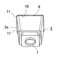
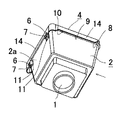
図1〜8は、本願請求項1〜4全てに対応した一実施形態である雨樋集水ますを示している。この実施形態の雨樋集水ますは、図1〜3に示すように、上方へ開口して底部に落とし口1が形成された器状のます本体2と、ます本体2の上方開口を塞ぐ板状で中程に排水管挿入口3が形成された蓋体4と、を備え、蓋体4に対します本体2が下方から係止して取り付けられるものである。そして、この雨樋集水ますにおいて、蓋体4の排水管挿入口3の周囲に天井面取付用の上方取付孔5を配設し、同蓋体4の後縁に壁面取付用の側方取付孔6を有する固定片7を垂設したものである。
FIGS. 1-8 has shown the rain gutter collecting basin which is one Embodiment corresponding to all Claims 1-4 of this application. As shown in FIGS. 1 to 3, the rain gutter collecting basin of this embodiment closes the upper opening of the
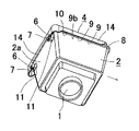
この実施形態の雨樋集水ますでは、図4にも示すように、ます本体2の上方開口の両側口縁に外方へ突出したフランジ片8を形成し、蓋体4の両側縁に下方内側へと屈曲した受け片9を形成し、受け片9にフランジ片8を前後方向スライド自在に係止して蓋体4にます本体2が取り付けられるようになしている。そして、この場合に、フランジ片8が受け片9から前方へと抜け外れるのを防止するストッパー手段(凸起10)を備えている。また、この実施形態の雨樋集水ますでは、図3に示すように、固定片7が有する側方取付孔6を蓋体4の後縁の両端部に配設し、両側方取付孔6を各々その中心軸線Xが後方内側へと傾斜するように形成している。
In the rain gutter collecting basin of this embodiment, as shown in FIG. 4,
以下、この実施形態の雨樋集水ますを、より具体的詳細に説明する。図1、2に示すように、この実施形態の雨樋集水ますは角ますであり、ます本体2が上方へ開口した平面視四角形状の箱型器状に形成されている。ます本体2は合成樹脂で一体に射出成型されたものであり、その上方開口の両側口縁に外方へ突出したフランジ片8が形成されている。両側のフランジ片8の下側には凸起10が突設されており、この両凸起10は、後述する蓋体4の受け片9の端部がこれに当止されて、この受け片9から同フランジ片8が前方へと抜け外れるのを防止するストッパー手段となる。なお、フランジ片8はます本体2の上方開口の両側口縁だけでなく、上方開口の口縁全周に亘って延設されている。
Hereinafter, the rain gutter collecting basin of this embodiment will be described in more detail. As shown in FIGS. 1 and 2, the rain gutter collecting basin of this embodiment is square, and the
ます本体2の後壁部2aの上部両側には、内側へ略V字状に屈曲してその外側部分に凹所11が形成されており、この凹所11には後述する蓋体4の固定片7の内側へ突出した傾斜部分が適合して納められる。ます本体2の底部には、図2に示すように、短円筒状の落とし口1が一体に垂設されており、この落とし口1には後述する鎖状樋17(図5)や竪樋18(図7)等が接続垂下される。
Further, on both sides of the upper portion of the
図1、3に示すように、蓋体4は前記ます本体2の上方開口に適合した四角形状で、合成樹脂にて一体に射出成型されたものである。蓋体4の中程には大きく四角形状に開口した排水管挿入口3が形成されており、この排水管挿入口3の内周には湾曲ガイド片12が全周に亘って垂設され、同排水管挿入口3には上方から排水管(図示せず)が挿入接続される。排水管挿入口3の周囲である蓋体4の四隅部分には、天井面取付用の上方取付孔5が穿設されており、この上方取付孔5に下方から挿通されるビス等の固定具によって、同蓋体4は後述(図5)する天井面Aに固定される。
As shown in FIGS. 1 and 3, the
蓋体4の両側縁には、図4にも示すように、下方内側へと屈曲した受け片9が形成されており、この受け片9には前記フランジ片8が前後方向スライド自在に係止されるものである。受け片9は略L字状に屈曲し、垂下する縦片部9aと内側へ突出する横片部9bとでなり、図3に示すように、蓋体4の両側縁の各中程で前後に別けて配設されている。また、射出成型時の型抜きのために、受け片9の横片部9bに対応させて蓋体4には抜き口13が形成されている。
As shown in FIG. 4, a receiving
前記受け片9の縦片部9aだけは蓋体4の両側縁の各中程だけでなく、蓋体4の両側縁及び後縁の全長に亘りカバー片14として延設されている。そして、後縁のカバー片14の両側端部分が更に下方へ延設されて固定片7となり、この固定片7には壁面取付用の側方取付孔6が穿設されている。両固定片7の前面は各々斜め外側を向くように傾斜しており、各固定片7に穿設される側方取付孔6は各々その中心軸線Xが後方内側へと傾斜するように形成されていて、両側方取付孔6に前方斜め外側から挿通されるビス等の固定具によって、蓋体4は同固定片7を介して後述(図7)する壁面Bに固定される。
Only the
また、図1に示すように、前記上方取付孔5及び抜き口13の各周囲には、蓋体4の上面に突出した厚肉部15が形成され、同蓋体4の外周縁には全周に亘って上方へ突出した凸リブ16が形成されており、これ等厚肉部15及び凸リブ16によって蓋体4は補強されている。そして、厚肉部15及び凸リブ16の各上端は同一高さに設定されており、蓋体4を後述(図5)する天井面Aに固定した際に、厚肉部15及び凸リブ16の各上端が天井面Aに当接されて、蓋体4は安定した状態で確実に固定される。
Further, as shown in FIG. 1, a
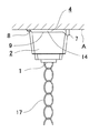
したがって、この実施形態の雨樋集水ますにおいては、蓋体4の排水管挿入口3の周囲に天井面取付用の上方取付孔5が配設されているので、この上方取付孔5に挿通されるビス(図示せず)によって、蓋体4を玄関ポーチ屋根やバルコニー等の下面、軒天井面等の天井面Aに安定させて固定することができるものであり、この施工形態を図5に示す。この場合、ます本体2の落とし口1には鎖状樋17が接続垂下されており、蓋体4の排水管挿入口3には屋上やバルコニー等から配管垂設される排水管(図示せず)が挿入接続される。なお、ます本体2の落とし口1には、後述する図7と同様に、竪樋18が接続垂下されてもよい。
Therefore, in the rain gutter collecting basin of this embodiment, since the upper mounting
そして、この施工形態では、図6に示すように、ます本体2を蓋体4に対し最後端位置までスライドさせてやることで、両者が違和感なくコンパクトに組み合わされて外観良く納まる。この場合、固定片7の傾斜して突出した前面部分はます本体2の後壁部2aの両凹所11に各々適合して納められ、ます本体2の上方開口における両側縁及び後縁の外側が蓋体4のカバー片14で覆い隠されて体裁良く納まるものである。
In this construction mode, as shown in FIG. 6, the
また別に、蓋体4の後縁には壁面取付用の側方取付孔6を有する固定片7が垂設されているので、この側方取付孔6に挿通されるビス(図示せず)によって、蓋体4を建物の外壁面等の壁面Bに固定片7を介し安定させて固定することができるものであり、この施工形態を図7に示す。この場合、ます本体2の落とし口1には竪樋18が接続垂下されており、この竪樋18は壁面Bに樋保持具19で固定され、同壁面Bに対し所定の距離を隔てて支持されている。蓋体4の排水管挿入口3には、屋根上や屋上から配管される等して壁面Bに突設される排水管(図示せず)が挿入接続される。
In addition, since a fixing
そして、この施工形態では、図8に示すように、ます本体2を蓋体4に対し前方へスライドさせて施工現場に適合した出具合にしてやることで、前述した図7のように、ます本体2が竪樋18と共に壁面Bに対して距離を隔てた所定の位置で確実に支持される。この場合、ます本体2が前方へスライド移動し過ぎて蓋体4から外れようとしても、ます本体2のフランジ片8の凸起10が蓋体4の受け片9の端部(後側の受け片9の横片部9bの後端)に当止してストッパー作用をなすので、フランジ片8の前方への抜け外れは防止され、ます本体2の蓋体4からの脱落が防止されて安全である。
In this construction mode, as shown in FIG. 8, the
また、ます本体2の上方開口の両側口縁に外方へ突出したフランジ片8が形成され、蓋体4の両側縁に下方内側へと屈曲した受け片9が形成され、受け片9にフランジ片8が前後方向スライド自在に係止されているので、前記出具合の調整作業におけるスライド操作はスムーズに行われるものであり、この場合、摺動するフランジ片8がその外側を受け片9で覆われる形で係止されているので、同スライド操作は蓋体4が固定された後でも支障なく行われるものである。
In addition,
更に、図3にて説明したように、固定片7の側方取付孔6はその中心軸線Xが後方内側へと傾斜するように形成されているので、両側方取付孔6にはその前方斜め外側からビス等の固定具を容易に挿通させることができ、この固定具による蓋体4の固定作業は行い易くなる。そして、上記いずれの施工形態にあっても、固定された蓋体4に対します本体2が下方からスライド操作により係止して簡単に取り付けられ、このように、天井面A、壁面Bのいずれにも適合させて簡単に取り付けることができ、使い勝手は良好である。
Further, as described with reference to FIG. 3, the
1 落とし口
2 ます本体
3 排水管挿入口
4 蓋体
5 上方取付孔
6 側方取付孔
7 固定片
8 フランジ片
9 受け片
10 凸起(ストッパー手段)
X 中心軸線
A 天井面
B 壁面
DESCRIPTION OF
X Center axis A Ceiling surface B Wall surface
Claims (4)
Priority Applications (1)
| Application Number | Priority Date | Filing Date | Title |
|---|---|---|---|
| JP2005289579A JP2007100331A (en) | 2005-10-03 | 2005-10-03 | Rain gutter water collection basin |
Applications Claiming Priority (1)
| Application Number | Priority Date | Filing Date | Title |
|---|---|---|---|
| JP2005289579A JP2007100331A (en) | 2005-10-03 | 2005-10-03 | Rain gutter water collection basin |
Publications (1)
| Publication Number | Publication Date |
|---|---|
| JP2007100331A true JP2007100331A (en) | 2007-04-19 |
Family
ID=38027538
Family Applications (1)
| Application Number | Title | Priority Date | Filing Date |
|---|---|---|---|
| JP2005289579A Pending JP2007100331A (en) | 2005-10-03 | 2005-10-03 | Rain gutter water collection basin |
Country Status (1)
| Country | Link |
|---|---|
| JP (1) | JP2007100331A (en) |
Cited By (1)
| Publication number | Priority date | Publication date | Assignee | Title |
|---|---|---|---|---|
| JP2014002663A (en) * | 2012-06-20 | 2014-01-09 | New Cosmos Electric Corp | Drain structure of electrical apparatus |
Citations (3)
| Publication number | Priority date | Publication date | Assignee | Title |
|---|---|---|---|---|
| JPS6450527U (en) * | 1987-09-25 | 1989-03-29 | ||
| JPH0428538U (en) * | 1990-06-29 | 1992-03-06 | ||
| JP2003227219A (en) * | 2002-02-01 | 2003-08-15 | Wakai & Co Ltd | Hanging device for painting etc. |
-
2005
- 2005-10-03 JP JP2005289579A patent/JP2007100331A/en active Pending
Patent Citations (3)
| Publication number | Priority date | Publication date | Assignee | Title |
|---|---|---|---|---|
| JPS6450527U (en) * | 1987-09-25 | 1989-03-29 | ||
| JPH0428538U (en) * | 1990-06-29 | 1992-03-06 | ||
| JP2003227219A (en) * | 2002-02-01 | 2003-08-15 | Wakai & Co Ltd | Hanging device for painting etc. |
Cited By (1)
| Publication number | Priority date | Publication date | Assignee | Title |
|---|---|---|---|---|
| JP2014002663A (en) * | 2012-06-20 | 2014-01-09 | New Cosmos Electric Corp | Drain structure of electrical apparatus |
Similar Documents
| Publication | Publication Date | Title |
|---|---|---|
| US9009880B2 (en) | Cover box for a shower flow system | |
| JP2007100331A (en) | Rain gutter water collection basin | |
| KR200480099Y1 (en) | Apparatus For Receiving Rainwater For Window Frame | |
| KR20140088429A (en) | a drain trap | |
| JP2534151Y2 (en) | Rain gutter collecting | |
| KR101863137B1 (en) | Base for handrail support | |
| US20160115680A1 (en) | Air Gap Cover | |
| JP4821631B2 (en) | Gutter collection | |
| EP3014029B1 (en) | Siphon unit | |
| GB2365765A (en) | Divider means for walk-in bath | |
| JP5904462B2 (en) | Pushbutton guide member having a metal plate flange member for a remotely operated drain plug device | |
| CN201891221U (en) | roof drain receiver | |
| JP2516922Y2 (en) | Drain trap and drain unit using it | |
| CN114052540A (en) | Can realize bathroom cabinet that pipeline is hidden | |
| JP4419974B2 (en) | Drain valve operation device | |
| JP2006316532A (en) | Rain gutter catchment basin | |
| JPS5915996Y2 (en) | washbasin unit | |
| JPS5812678Y2 (en) | Air pot spout structure | |
| JPH088177Y2 (en) | Eaves gutter drainage system | |
| JP2558342Y2 (en) | Rain gutter collecting | |
| JP2007002539A (en) | Structure of mounting catch basin to wall surface | |
| JP4807233B2 (en) | Dredge equipment | |
| CN205865502U (en) | Novel dog lavatory | |
| JP2006063518A (en) | Washstand | |
| JP2008127861A (en) | Rain-gutter catch basin |
Legal Events
| Date | Code | Title | Description |
|---|---|---|---|
| A621 | Written request for application examination |
Free format text: JAPANESE INTERMEDIATE CODE: A621 Effective date: 20080123 |
|
| A977 | Report on retrieval |
Free format text: JAPANESE INTERMEDIATE CODE: A971007 Effective date: 20100830 |
|
| A131 | Notification of reasons for refusal |
Free format text: JAPANESE INTERMEDIATE CODE: A131 Effective date: 20100907 |
|
| A02 | Decision of refusal |
Free format text: JAPANESE INTERMEDIATE CODE: A02 Effective date: 20110105 |