JP2007106930A - Film-forming composition, antireflection film, polarizing plate, and image display device - Google Patents
Film-forming composition, antireflection film, polarizing plate, and image display device Download PDFInfo
- Publication number
- JP2007106930A JP2007106930A JP2005300395A JP2005300395A JP2007106930A JP 2007106930 A JP2007106930 A JP 2007106930A JP 2005300395 A JP2005300395 A JP 2005300395A JP 2005300395 A JP2005300395 A JP 2005300395A JP 2007106930 A JP2007106930 A JP 2007106930A
- Authority
- JP
- Japan
- Prior art keywords
- film
- refractive index
- fluorine
- layer
- index layer
- Prior art date
- Legal status (The legal status is an assumption and is not a legal conclusion. Google has not performed a legal analysis and makes no representation as to the accuracy of the status listed.)
- Pending
Links
- 0 *OCCC(C1C(C(N2CO*)N3CO*)N(CO*)C2=O)C1C3=O Chemical compound *OCCC(C1C(C(N2CO*)N3CO*)N(CO*)C2=O)C1C3=O 0.000 description 1
Images

Landscapes
- Surface Treatment Of Optical Elements (AREA)
- Laminated Bodies (AREA)
- Compositions Of Macromolecular Compounds (AREA)
- Paints Or Removers (AREA)
- Addition Polymer Or Copolymer, Post-Treatments, Or Chemical Modifications (AREA)
- Polarising Elements (AREA)
Abstract
【課題】大量生産に適した塗布型の反射防止フィルム作製のための皮膜形成用組成物、この皮膜形成用組成物を用いた、十分な反射防止能、耐擦傷性を有すると共に、防汚性の向上した反射防止フィルム、及びこの反射防止フィルムを用いた偏光板や画像表示装置を提供する。
【解決手段】主鎖にポリシロキサンセグメントを有するフッ素含有共重合体と、主鎖が炭素原子のみからなるフッ素含有共重合体とを、それぞれ少なくとも一種含み、かつ、主鎖にポリシロキサンセグメントを有するフッ素含有共重合体の含有率が共重合体全体に対して30質量%以下である皮膜形成用組成物。この皮膜形成用組成物を、透明支持体上に塗設することにより形成される低屈折率層を含む反射防止フィルム。この反射防止フィルムが偏光膜の2枚の保護フィルムのうち、一方に用いられている偏光板。これら反射防止フィルム又は偏光板がディスプレイの最表面に用いられている画像表示装置。
【選択図】なし[PROBLEMS] To provide a film-forming composition for preparing a coating-type anti-reflection film suitable for mass production, and having sufficient anti-reflection ability, scratch resistance and antifouling property using this film-forming composition. Improved antireflection film, and a polarizing plate and an image display device using the antireflection film are provided.
The main chain contains at least one fluorine-containing copolymer having a polysiloxane segment in the main chain and a fluorine-containing copolymer having a main chain composed of only carbon atoms, and has a polysiloxane segment in the main chain. The composition for film formation whose content rate of a fluorine-containing copolymer is 30 mass% or less with respect to the whole copolymer. An antireflection film comprising a low refractive index layer formed by coating the film-forming composition on a transparent support. A polarizing plate in which this antireflection film is used for one of two protective films of a polarizing film. An image display device in which these antireflection films or polarizing plates are used on the outermost surface of the display.
[Selection figure] None
Description
本発明は、主鎖が炭素原子のみからなるフッ素含有共重合体と、主鎖にポリシロキサンセグメントを有するフッ素含有共重合体とを含有する皮膜形成用組成物、及び該皮膜形成用組成物を用いた反射防止フィルム、並びに該反射防止フィルムを用いた偏光板及び画像表示装置に関する。 The present invention relates to a film-forming composition comprising a fluorine-containing copolymer having a main chain composed only of carbon atoms, and a fluorine-containing copolymer having a polysiloxane segment in the main chain, and the film-forming composition. The present invention relates to an antireflection film used, and a polarizing plate and an image display device using the antireflection film.
反射防止フィルムは、一般に、陰極管表示装置(CRT)、プラズマディスプレイ(PDP)、エレクトロルミネッセンスディスプレイ(ELD)や液晶表示装置(LCD)などのような画像表示装置において、外光の反射によるコントラスト低下や像の映り込みを防止するために、光学干渉の原理を用いて反射率を低減する様ディスプレイの最表面に配置される。 In general, an antireflection film is used for an image display device such as a cathode ray tube display (CRT), a plasma display (PDP), an electroluminescence display (ELD), a liquid crystal display (LCD), etc. In order to prevent reflection of images and images, it is arranged on the outermost surface of the display so as to reduce the reflectance by using the principle of optical interference.
このような反射防止フィルムは、一般的には、支持体又はその上に形成されている高屈折率層の上に、適切な膜厚の低屈折率層を形成することにより作製できる。低屈折率層の素材としては、反射防止性能の観点から可能な限り屈折率の低い素材が望まれ、同時にディスプレイの最表面に用いられるため高い耐擦傷性が要求される。厚さ100nm前後の薄膜において高い耐擦傷性を実現するためには、皮膜自体の強度、及び下層への密着性を高めることが重要である。 Such an antireflection film can be generally produced by forming a low refractive index layer having an appropriate thickness on a support or a high refractive index layer formed thereon. As a material for the low refractive index layer, a material having a refractive index as low as possible is desired from the viewpoint of antireflection performance, and at the same time, since it is used for the outermost surface of the display, high scratch resistance is required. In order to realize high scratch resistance in a thin film having a thickness of around 100 nm, it is important to increase the strength of the coating itself and the adhesion to the lower layer.
材料の屈折率を下げるには、(1)フッ素原子を導入する、(2)密度を下げる(空隙を導入する)などの手段があるが、いずれも皮膜強度や界面の密着性が低下し、耐擦傷性が低下する方向であり、低い屈折率と高い耐傷性の両立は困難な課題であった。また反射防止フィルムはディスプレイなどの最表面に設置することから、汚れを付着しにくくしたり、付着した汚れを拭き取りやすくしたりといった、防汚性向上も課題であった。 In order to lower the refractive index of the material, there are means such as (1) introducing fluorine atoms, (2) lowering the density (introducing voids), etc., both of which decrease the film strength and interface adhesion, The scratch resistance is in the direction of decreasing, and it has been a difficult task to achieve both low refractive index and high scratch resistance. In addition, since the antireflection film is installed on the outermost surface of a display or the like, improvement of antifouling properties such as making it difficult to adhere dirt and facilitating wiping off the attached dirt has been a problem.
特許文献1及び特許文献2には、含フッ素ポリマーを塗布後硬化させて低屈折率層を形成する技術が提案されている。
特許文献3及び特許文献4には、含フッ素ポリマー中にポリシロキサン構造を導入することにより滑り性を付与し、耐擦傷性を改良する技術が提案されている。
特許文献5には、フッ素含有ポリマー中にポリシロキサン構造を導入し、且つ水酸基の含率を高くする技術が提案されている。
特許文献1及び特許文献2の技術では、耐擦傷性も防汚性も不十分であった。
The techniques of Patent Document 1 and
特許文献3及び特許文献4の技術を用いると、皮膜表面の摩擦係数が下がり、耐擦傷性改良に対してある程度有効であるが、本質的な皮膜強度及び界面密着性が不足しているよ
うな皮膜に対しては、該技術のみでは十分な耐擦傷性が得られない。
When the techniques of
耐擦傷性については、特許文献5の技術によって改善されている。
The scratch resistance is improved by the technique of
しかしながら、防汚性については、特許文献3〜5の技術において、ポリシロキサン構造を導入することで付与されるものの、さらに改良が必要なレベルであった。しかも、導入するポリシロキサン構造の含有量を制御するには、製造段階において対処する必要があり、諸性能とのバランスを調整するのは必ずしも容易ではない。
However, the antifouling property was provided by introducing a polysiloxane structure in the techniques of
本発明は、第1に大量生産に適した塗布型の反射防止フィルム作製のための皮膜形成用組成物を提供することであり、第2にこのような皮膜形成用組成物を用いて、十分な反射防止能、耐擦傷性を有する反射防止フィルムを提供することであり、第3に防汚性の向上した反射防止フィルムを提供することであり、さらにはそのような反射防止フィルムを用いた偏光板や画像表示装置を提供することにある。 The present invention firstly provides a film-forming composition for producing a coating-type antireflection film suitable for mass production, and secondly, using such a film-forming composition, Providing an antireflection film having excellent antireflection performance and scratch resistance, and thirdly, providing an antireflection film with improved antifouling properties, and further using such an antireflection film. The object is to provide a polarizing plate and an image display device.
本発明者らは鋭意検討の結果、ポリシロキサンセグメントを有する含フッ素共重合体と、ポリシロキサンセグメントを含まない含フッ素共重合体とを特定の割合で含んでなる低屈折率層を用いることにより、反射率が低く、耐擦傷性、防汚性に優れた反射防止膜を得た。
すなわち本発明の上記課題は、以下の手段によって達成された。
As a result of intensive studies, the present inventors have used a low refractive index layer comprising a fluorine-containing copolymer having a polysiloxane segment and a fluorine-containing copolymer not containing a polysiloxane segment in a specific ratio. Thus, an antireflection film having low reflectivity and excellent scratch resistance and antifouling properties was obtained.
That is, the said subject of this invention was achieved by the following means.
[1]主鎖にポリシロキサンセグメントを有するフッ素含有共重合体と、主鎖が炭素原子のみからなるフッ素含有共重合体とを、それぞれ少なくとも一種含み、かつ、主鎖にポリシロキサンセグメントを有するフッ素含有共重合体の含有率が共重合体全体に対して30質量%以下であることを特徴とする皮膜形成用組成物。 [1] Fluorine containing at least one fluorine-containing copolymer having a polysiloxane segment in the main chain and a fluorine-containing copolymer having a main chain consisting of only carbon atoms, and having a polysiloxane segment in the main chain A film-forming composition, wherein the content of the containing copolymer is 30% by mass or less based on the entire copolymer.
[2]主鎖にポリシロキサンセグメントを有するフッ素含有共重合体が、下記一般式(1)で表される構造を含む上記[1]に記載の皮膜形成用組成物。
一般式(1):
[2] The film forming composition according to [1], wherein the fluorine-containing copolymer having a polysiloxane segment in the main chain includes a structure represented by the following general formula (1).
General formula (1):
一般式(1)において、Rf11は炭素数1〜5のペルフルオロアルキル基を表し、Rf12は炭素数1〜30の含フッ素アルキル基を表し、Aは水酸基含有ビニルモノマー重合単位を表し、Bは任意の構成成分を表し、R11、R12は同一であっても異なっていてもよく、アルキル基又はアリール基を表す。a1〜e1はそれぞれ各構成成分のモル分率(%)を表し、それぞれ0<a1<50、0≦b1≦40、0<c1≦10、0≦d1<50、10≦e1<100の関係を満たす。 In the general formula (1), Rf 11 represents a perfluoroalkyl group having 1 to 5 carbon atoms, Rf 12 represents a fluorine-containing alkyl group having 1 to 30 carbon atoms, A represents a hydroxyl group-containing vinyl monomer polymerization unit, B Represents an optional component, and R 11 and R 12 may be the same or different and each represents an alkyl group or an aryl group. a1 to e1 each represent a mole fraction (%) of each constituent component, and relationships of 0 <a1 <50, 0 ≦ b1 ≦ 40, 0 <c1 ≦ 10, 0 ≦ d1 <50, 10 ≦ e1 <100, respectively. Meet.
[3]主鎖が炭素原子のみからなるフッ素含有共重合体が、下記一般式(2)で表される構造を含む上記[1]に記載の皮膜形成用組成物。
一般式(2):
[3] The film-forming composition as described in [1] above, wherein the fluorine-containing copolymer whose main chain consists only of carbon atoms includes a structure represented by the following general formula (2).
General formula (2):
一般式(2)において、Rf11は炭素数1〜5のペルフルオロアルキル基を表し、Rf12は炭素数1〜30の含フッ素アルキル基を表し、Aは水酸基含有ビニルモノマー重合単位を表し、Bは任意の構成成分を表す。a2〜d2はそれぞれ各構成成分のモル分率(%)を表し、それぞれ30≦a2≦70、0≦b2≦40、0<c2≦70、0≦d2≦40の関係を満たす。 In the general formula (2), Rf 11 represents a perfluoroalkyl group having 1 to 5 carbon atoms, Rf 12 represents a fluorine-containing alkyl group having 1 to 30 carbon atoms, A represents a hydroxyl group-containing vinyl monomer polymerization unit, B Represents an optional component. a2 to d2 each represent a mole fraction (%) of each constituent component, and satisfy the relationships of 30 ≦ a2 ≦ 70, 0 ≦ b2 ≦ 40, 0 <c2 ≦ 70, and 0 ≦ d2 ≦ 40, respectively.
[4]皮膜形成用組成物がさらに、いずれかのフッ素含有共重合体に含まれる水酸基と反応可能な架橋剤を含む上記[1]〜[3]のいずれかに記載の皮膜形成用組成物。 [4] The film-forming composition according to any one of [1] to [3], wherein the film-forming composition further comprises a crosslinking agent capable of reacting with a hydroxyl group contained in any of the fluorine-containing copolymers. .
[5]皮膜形成用組成物がさらに無機微粒子を含有する上記[1]〜[4]のいずれかに記載の皮膜形成用組成物。 [5] The film forming composition according to any one of [1] to [4], wherein the film forming composition further contains inorganic fine particles.
[6]透明支持体上に、低屈折率層を有する反射防止フィルムであって、該低屈折率層が上記[1]〜[5]のいずれかに記載の皮膜形成用組成物から形成されたことを特徴とする反射防止フィルム。 [6] An antireflection film having a low refractive index layer on a transparent support, wherein the low refractive index layer is formed from the film forming composition according to any one of [1] to [5]. An antireflection film characterized by that.
[7]上記[6]に記載の反射防止フィルムが、偏光板における偏光膜の2枚の保護フィルムのうち、一方に用いられていることを特徴とする偏光板。 [7] A polarizing plate, wherein the antireflection film according to [6] is used for one of the two protective films of the polarizing film in the polarizing plate.
[8]上記[6]に記載の反射防止フィルム又は、上記[7]に記載の偏光板がディスプレイの最表面に用いられていることを特徴とする画像表示装置。 [8] An image display device, wherein the antireflection film according to [6] or the polarizing plate according to [7] is used on the outermost surface of the display.
本発明の皮膜形成用組成物は、フッ素含率が高いため得られる皮膜の屈折率が低い。また該皮膜形成用組成物により形成された反射防止フィルムは、反射防止能が高く、耐擦傷性に優れている。またポリシロキサンセグメントを含有するため、滑り性が付与されており、耐擦傷性が向上し、さらに防汚性にも優れている。この反射防止フィルムを用いた偏光板及び液晶表示装置は、外光の映り込みが十分に防止されているうえ、耐擦傷性が高く、さらに優れた防汚性をも有する。 Since the film forming composition of the present invention has a high fluorine content, the refractive index of the film obtained is low. Moreover, the antireflection film formed from the film forming composition has high antireflection ability and excellent scratch resistance. In addition, since it contains a polysiloxane segment, it is given slipperiness, improved scratch resistance, and excellent antifouling properties. A polarizing plate and a liquid crystal display device using this antireflection film are sufficiently prevented from reflecting external light, have high scratch resistance, and have excellent antifouling properties.
本明細書において「〜」とは、その前後に記載される数値を下限値及び上限値として含む意味で使用される。また、本発明でいう「重合」には、共重合も含む趣旨である。さらに、本発明でいう「支持体上」には、該支持体等の直接の表面をいう場合と、該支持体等の上に何らかの層(膜)を設けた表面をいう場合の両方を含む趣旨である。 In the present specification, “to” is used to mean that the numerical values described before and after it are included as a lower limit value and an upper limit value. The term “polymerization” as used in the present invention is intended to include copolymerization. Furthermore, “on the support” as used in the present invention includes both the case where it refers to the direct surface of the support and the like and the case where it refers to the surface provided with any layer (film) on the support or the like. It is the purpose.
<皮膜形成用組成物>
本発明の皮膜形成用組成物は、主鎖にポリシロキサンセグメントを有するフッ素含有共重合体と、主鎖が炭素原子のみからなるフッ素含有共重合体とをそれぞれ少なくとも1種ずつ含み、かつ、主鎖にポリシロキサンセグメントを有するフッ素含有共重合体の含有率が、フッ素含有共重合体の総量に対して30質量%以下であることを特徴とする。
以下、それぞれのフッ素含有共重合体について説明する。
<Film-forming composition>
The film-forming composition of the present invention comprises at least one fluorine-containing copolymer having a polysiloxane segment in the main chain and at least one fluorine-containing copolymer having a main chain composed only of carbon atoms. The content of the fluorine-containing copolymer having a polysiloxane segment in the chain is 30% by mass or less based on the total amount of the fluorine-containing copolymer.
Hereinafter, each fluorine-containing copolymer will be described.
〔フッ素含有共重合体〕
[主鎖にポリシロキサンセグメントを有するフッ素含有共重合体]
主鎖にポリシロキサンセグメントを有するフッ素含有共重合体の構成する重合単位の構造は、ポリシロキサンセグメントとフッ素原子とを必須成分として有していれば特に制限なく、フッ素原子を含むモノマーとして、例えば含フッ素オレフィン、ペルフルオロアルキルビニルエーテル、含フッ素アルキル基を有するビニルエーテルや(メタ)アクリレートなどに基づく重合単位を挙げることができる。
[Fluorine-containing copolymer]
[Fluorine-containing copolymer having polysiloxane segments in the main chain]
The structure of the polymerization unit constituting the fluorine-containing copolymer having a polysiloxane segment in the main chain is not particularly limited as long as it has a polysiloxane segment and a fluorine atom as essential components. Examples thereof include polymerized units based on fluorine-containing olefins, perfluoroalkyl vinyl ethers, vinyl ethers having fluorine-containing alkyl groups, (meth) acrylates, and the like.
中でも、主鎖にポリシロキサンセグメントを有するフッ素含有共重合体としては、下記一般式(1)で表される共重合体であることが好ましい。
一般式(1):
Especially, as a fluorine-containing copolymer which has a polysiloxane segment in a principal chain, it is preferable that it is a copolymer represented by following General formula (1).
General formula (1):
一般式(1)において、Rf11は炭素数1〜5のペルフルオロアルキル基を表し、Rf12は炭素数1〜30の含フッ素アルキル基を表し、Aは水酸基含有ビニルモノマー重合単位を表し、Bは任意の構成成分を表し、R11、R12は同一であっても異なっていてもよく、アルキル基又はアリール基を表す。a1〜e1はそれぞれ各構成成分のモル分率(%)を表し、それぞれ0<a1<50、0≦b1≦40、0<c1≦10、0≦d1<50、10≦e1<100の関係を満たす。 In the general formula (1), Rf 11 represents a perfluoroalkyl group having 1 to 5 carbon atoms, Rf 12 represents a fluorine-containing alkyl group having 1 to 30 carbon atoms, A represents a hydroxyl group-containing vinyl monomer polymerization unit, B Represents an optional component, and R 11 and R 12 may be the same or different and each represents an alkyl group or an aryl group. a1 to e1 each represent a mole fraction (%) of each constituent component, and relationships of 0 <a1 <50, 0 ≦ b1 ≦ 40, 0 <c1 ≦ 10, 0 ≦ d1 <50, 10 ≦ e1 <100, respectively. Meet.
(一般式M1又はM2で表されるフッ素含有モノマー成分)
上記一般式(1)の共重合体は、下記一般式M1又はM2で表されるフッ素含有モノマー成分と、水酸基含有ビニルモノマー重合単位A及び任意の構成成分Bを形成するモノマー成分、及び主鎖にポリシロキサンセグメントを含む構成成分からなるランダム共重合体である。これらそれぞれの一般式で表される構成成分は、それぞれ1種類で構成されていても、複数のモノマーによって構成されていてもよい。
(Fluorine-containing monomer component represented by general formula M1 or M2)
The copolymer of the general formula (1) includes a fluorine-containing monomer component represented by the following general formula M1 or M2, a monomer component that forms a hydroxyl group-containing vinyl monomer polymerization unit A and an optional component B, and a main chain. The random copolymer which consists of a structural component containing a polysiloxane segment. Each of the constituent components represented by the respective general formulas may be composed of one kind or a plurality of monomers.
一般式M1中、Rf11は炭素数1〜5のペルフルオロアルキル基を表し、重合反応性の観点からはペルフルオロメチル基又はペルフルオロエチル基が好ましく、入手性の観点からペルフルオロメチル基{一般式M1で表されるペルフルオロオレフィンモノマーとしては、ヘキサフルオロプロピレン(HFP)を表す}であることが特に好ましい。 In the general formula M1, Rf 11 represents a C 1-5 perfluoroalkyl group, preferably a perfluoromethyl group or a perfluoroethyl group from the viewpoint of polymerization reactivity, and a perfluoromethyl group {in the general formula M1 from the viewpoint of availability. The perfluoroolefin monomer represented is particularly preferably hexafluoropropylene (HFP)}.
これら一般式M1で表されるモノマーの導入量、すなわち前記一般式(1)におけるa1の値は、0<a1<50モル%の範囲であり、0<a1<25モル%の範囲であることが好ましく、共重合体のポリシロキサンセグメントの導入率を高めるために、0<a1<15モル%の範囲であることがより好ましい。 The introduction amount of the monomer represented by the general formula M1, that is, the value of a1 in the general formula (1) is in the range of 0 <a1 <50 mol% and 0 <a1 <25 mol%. In order to increase the introduction rate of the polysiloxane segment of the copolymer, it is more preferable that the range is 0 <a1 <15 mol%.
一般式M2中、Rf12は炭素数1〜30の含フッ素アルキル基を表し、好ましくは炭素数1〜20、特に好ましくは炭素数1〜10の含フッ化アルキル基であり、炭素数1〜10のペルフルオロアルキル基であることがさらに好ましい。また、該フッ化アルキル基は置換基を有していてもよい。Rf12の具体例としては、−CF3[M2−(1)]、−CF2CF3[M2−(2)]、−CF2CF2CF3[M2−(3)]、−CF2CF(OCF2CF2CF3)CF3[M2−(4)]などが挙げられる。
In the Formula M2, Rf 12 represents a fluorine-containing alkyl group having 1 to 30 carbon atoms, preferably 1 to 20 carbon atoms, particularly preferably containing fluorinated alkyl group having 1 to 10 carbon atoms, 1 to carbon atoms More preferably, it is 10 perfluoroalkyl groups. The fluorinated alkyl group may have a substituent. Specific examples of Rf 12, -CF 3 [M2- ( 1)], -
これら一般式M2で表されるモノマーの導入量、すなわち一般式(1)におけるb1の値は、0≦b1≦40モル%の範囲であり、0≦b1<20モル%の範囲であることが好ましく、M1と同様、共重合体のポリシロキサンセグメントの導入率を高めるために、0≦b1<10モル%の範囲であることがより好ましい。 The introduction amount of the monomer represented by the general formula M2, that is, the value of b1 in the general formula (1) is in the range of 0 ≦ b1 ≦ 40 mol% and 0 ≦ b1 <20 mol%. Preferably, similarly to M1, in order to increase the introduction rate of the polysiloxane segment of the copolymer, it is more preferable that the range is 0 ≦ b1 <10 mol%.
(水酸基含有ビニルモノマー重合単位A)
水酸基含有ビニルモノマーは、前述した含フッ素ビニルモノマー重合単位と共重合可能なものであれば、ビニルエーテル類、(メタ)アクリレート類、スチレン類など、特に制限なく使用することができる。例えば含フッ素ビニルモノマーとしてペルフルオロオレフィン(ヘキサフルオロプロピレンなど)を用いた場合には、共重合性が良好な水酸基含有ビニルエーテルを用いることが好ましく、具体的には2−ヒドロキシエチルビニルエーテル、4−ヒドロキシブチルビニルエーテル、6−ヒドロキシヘキシルビニルエーテル、8−ヒドロキシオクチルビニルエーテル、ジエチレングリコールビニルエーテル、トリエチレングリコールビニルエーテル、4−(ヒドロキシメチル)シクロヘキシルメチルビニルエーテルなどが挙げられるが、これらに限定されるものではない。
(Hydroxyl group-containing vinyl monomer polymerization unit A)
As the hydroxyl group-containing vinyl monomer, any vinyl ethers, (meth) acrylates, styrenes and the like can be used as long as they are copolymerizable with the above-described fluorine-containing vinyl monomer polymerization unit. For example, when a perfluoroolefin (such as hexafluoropropylene) is used as the fluorine-containing vinyl monomer, it is preferable to use a hydroxyl group-containing vinyl ether having good copolymerization properties, specifically 2-hydroxyethyl vinyl ether, 4-hydroxybutyl. Examples include, but are not limited to, vinyl ether, 6-hydroxyhexyl vinyl ether, 8-hydroxyoctyl vinyl ether, diethylene glycol vinyl ether, triethylene glycol vinyl ether, 4- (hydroxymethyl) cyclohexyl methyl vinyl ether, and the like.
これら重合単位Aの導入量、すなわち一般式(1)におけるc1の値は、0<c1≦10モル%の範囲であり、2≦c1≦10モル%の範囲であることが好ましく、皮膜の硬度を高め、かつ、共重合体のポリシロキサンセグメントの導入率を高めるために4≦c1≦10モル%の範囲であることがより好ましい。 The introduction amount of these polymerization units A, that is, the value of c1 in the general formula (1) is in the range of 0 <c1 ≦ 10 mol%, preferably in the range of 2 ≦ c1 ≦ 10 mol%, and the hardness of the film In order to increase the ratio and increase the introduction rate of the polysiloxane segment of the copolymer, it is more preferable that the range is 4 ≦ c1 ≦ 10 mol%.
(任意の構成成分B)
上記以外の共重合成分、すなわち一般式(1)における構成成分Bで表したものとしては、硬度、基材への密着性、溶媒への溶解性、透明性等種々の観点から適宜選択することができる。例えば、メチルビニルエーテル、エチルビニルエーテル、t−ブチルビニルエーテル、n−ブチルビニルエーテル、シクロへキシルビニルエーテル、イソプロピルビニルエーテル等のビニルエーテル類、酢酸ビニル、プロピオン酸ビニル、酪酸ビニル、シクロヘキサンカルボン酸ビニル等のビニルエステル類を例として挙げることができる。
(Optional component B)
Copolymerization components other than those described above, that is, those represented by the component B in the general formula (1), are appropriately selected from various viewpoints such as hardness, adhesion to a substrate, solubility in a solvent, and transparency. Can do. For example, vinyl ethers such as methyl vinyl ether, ethyl vinyl ether, t-butyl vinyl ether, n-butyl vinyl ether, cyclohexyl vinyl ether, isopropyl vinyl ether, vinyl esters such as vinyl acetate, vinyl propionate, vinyl butyrate, vinyl cyclohexanecarboxylate, etc. As an example.
また、本発明では任意の構成成分Bとして、得られる皮膜形成用組成物を低屈折率層の形成に用いる場合には、形成皮膜の低屈折率化のため、下記一般式M3で表される含フッ素ビニルエーテルを共重合させてもよい。 In the present invention, when the obtained film-forming composition is used as the optional component B for forming the low refractive index layer, it is represented by the following general formula M3 in order to reduce the refractive index of the formed film. Fluorine-containing vinyl ether may be copolymerized.
一般式M3中、Rf13は炭素数1〜30の含フッ素アルキル基を表し、好ましくは炭素数1〜20、特に好ましくは炭素数1〜15の含フッ素アルキル基であり、直鎖{例えば−CF2CF3、−CH2(CF2)4H、−CH2(CF2)8CF3、−CH2CH2(CF2)4Hなど}であっても、分岐構造{例えばCH(CF3)2、CH2CF(CF3)2、−CH(CH3)CF2CF3、−CH(CH3)(CF2)5CF2Hなど}を有していてもよく、また脂環式構造(好ましくは5員環又は6員環、例えばペルフルオロシクロへキシル基、ペルフルオロシクロペンチル基又はこれらで置換されたアルキル基等)を有していてもよく、エーテル結合(例えばCH2OCH2CF2CF3、CH2CH2OCH2C4F8H、CH2CH2OCH2C6F12H、CH2CH2OCH2CH2C4F9、CH2CH2OCH2CH2C6F13、CH2CH2OCF2CF2OCF2CF2Hなど)を有していてもよい。
In the general formula M3, Rf 13 represents a fluorine-containing alkyl group having 1 to 30 carbon atoms, preferably a fluorine-containing alkyl group having 1 to 20 carbon atoms, particularly preferably 1 to 15 carbon atoms, CF 2 CF 3 , —CH 2 (CF 2 ) 4 H, —CH 2 (CF 2 ) 8 CF 3 , —CH 2 CH 2 (CF 2 ) 4 H, etc.} CF 3 ) 2 , CH 2 CF (CF 3 ) 2 , —CH (CH 3 ) CF 2 CF 3 , —CH (CH 3 ) (CF 2 ) 5 CF 2 H, etc.} It may have an alicyclic structure (preferably a 5- or 6-membered ring such as a perfluorocyclohexyl group, a perfluorocyclopentyl group or an alkyl group substituted with these), and an ether bond (for example, CH 2 OCH 2 CF 2 CF 3, CH 2 CH 2 OCH 2 C 4 F 8 H, H 2 CH 2 OCH 2 C 6 F 12 H,
一般式M3で表わされる上記単量体は、例えば、"Macromolecules",32巻(21)、p.7122(1999年)、特開平2−721号公報等に記載のごとくビニロキシアルキルスルホネート、ビニロキシアルキルクロリド等の離脱基置換アルキルビニルエーテル類に対して、塩基触媒存在下含フッ素アルコールを作用させる方法;国際出願特許第92/05135号パンフレット記載のごとく、含フッ素アルコールとブチルビニルエーテル等のビニルエーテル類をパラジウム触媒存在下混合してビニル基の交換を行う方法;米国特許第3420793号明細書記載のごとく、含フッ素ケトンとジブロモエタンをフッ化カリウム触媒存在化で反応させた後アルカリ触媒により脱HBr反応を行う方法;等により合成することができる。 Examples of the monomer represented by the general formula M3 include “Macromolecules”, Vol. 32 (21), p. 7122 (1999), a method in which a fluorine-containing alcohol is allowed to act on a leaving group-substituted alkyl vinyl ether such as vinyloxyalkyl sulfonate and vinyloxyalkyl chloride as described in JP-A-2-721. A method of exchanging vinyl groups by mixing a fluorine-containing alcohol and a vinyl ether such as butyl vinyl ether in the presence of a palladium catalyst as described in International Patent Application No. 92/05135; as described in US Pat. No. 3,420,793. , A method in which a fluorine-containing ketone and dibromoethane are reacted in the presence of a potassium fluoride catalyst, followed by a de-HBr reaction with an alkali catalyst;
これら構成成分Bの導入量、すなわち前記一般式(1)におけるd1の値は、0≦d1<50モル%の範囲であり、0≦d1≦30モル%の範囲であることが好ましく、共重合体のポリシロキサンセグメントの導入率を高めるために0≦d1≦20モル%の範囲であることがより好ましい。 The amount of component B introduced, that is, the value of d1 in the general formula (1) is in the range of 0 ≦ d1 <50 mol%, preferably in the range of 0 ≦ d1 ≦ 30 mol%. In order to increase the introduction rate of the polysiloxane segment of the coalescence, it is more preferable that the range is 0 ≦ d1 ≦ 20 mol%.
(ポリシロキサンセグメント)
前記一般式(1)におけるポリシロキサンセグメントのR11、R12は、同一であっても
異なっていてもよく、アルキル基又はアリール基を表す。主鎖骨格に導入されていればその導入法は限定されない。すなわち、ポリシロキサンセグメントの他に任意の構造を有してもよいが、操作の簡便さなどの観点から、高分子重合開始剤を用いることが好ましく、アゾ基やペルオキシ基等のラジカル発生可能な基を有するポリシロキサン化合物がこれにあたる。特に下記一般式(3)で表されるポリシロキサン構造を含むことがより好ましい。
一般式(3):
(Polysiloxane segment)
R 11 and R 12 of the polysiloxane segment in the general formula (1) may be the same or different and each represents an alkyl group or an aryl group. The introduction method is not limited as long as it is introduced into the main chain skeleton. That is, it may have an arbitrary structure in addition to the polysiloxane segment, but from the viewpoint of ease of operation, it is preferable to use a polymer polymerization initiator, and radicals such as azo groups and peroxy groups can be generated. This is the case with polysiloxane compounds having groups. In particular, it preferably contains a polysiloxane structure represented by the following general formula (3).
General formula (3):
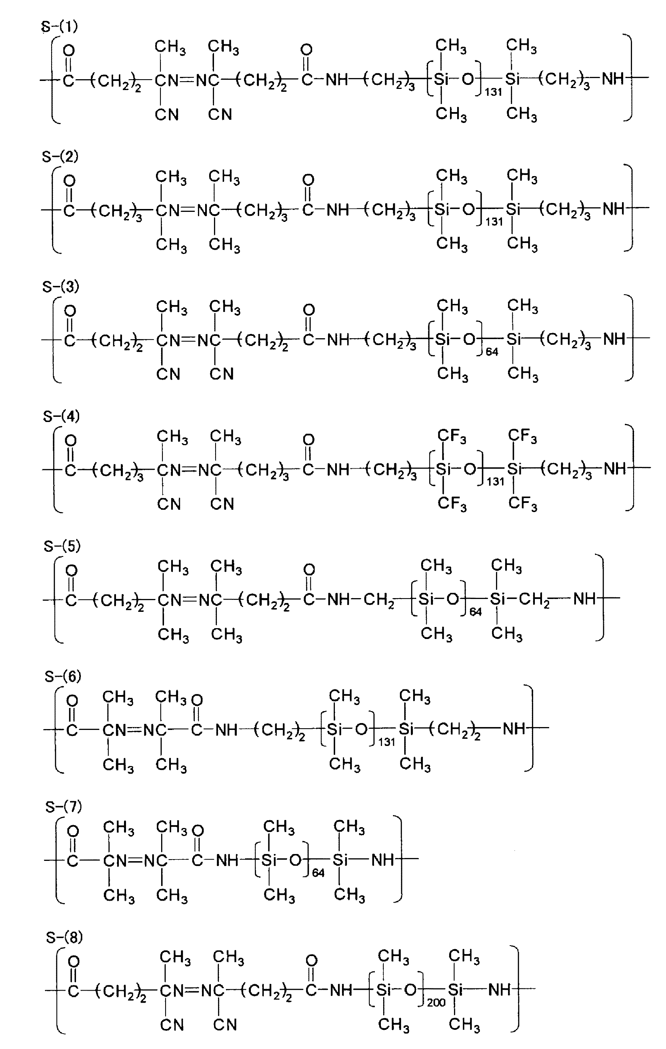
一般式(3)中、R11及びR12は、それぞれ独立して、アルキル基又はアリール基を表し、R13及びR14は、それぞれ独立して、水素原子、アルキル基、ハロアルキル基又はアリール基(好ましくはフェニル基)を表し、R15〜R18は、それぞれ独立して、水素原子、アルキル基、アリール基、アルコキシカルボニル基又はシアノ基を表す。q1、q2はそれぞれ独立して1〜10の整数を表す。q3、q4はそれぞれ独立して0〜10の整数を表す。pは10〜1000の整数を表す。 In General Formula (3), R 11 and R 12 each independently represent an alkyl group or an aryl group, and R 13 and R 14 each independently represent a hydrogen atom, an alkyl group, a haloalkyl group, or an aryl group. (Preferably a phenyl group), and R 15 to R 18 each independently represents a hydrogen atom, an alkyl group, an aryl group, an alkoxycarbonyl group or a cyano group. q1 and q2 each independently represents an integer of 1 to 10. q3 and q4 each independently represents an integer of 0 to 10. p represents an integer of 10 to 1000.
上記一般式(3)で表される重合開始剤は、例えば特公平6−104711号公報、特開平6−93100号公報等に記載のごとくに合成できる。 The polymerization initiator represented by the general formula (3) can be synthesized as described in, for example, JP-B-6-104711, JP-A-6-93100, and the like.
こうした高分子重合開始剤のうち好ましいものの例を以下に示すが、本発明はこれらによって何ら限定されるものではない。 Examples of preferred polymer polymerization initiators are shown below, but the present invention is not limited thereto.
ポリシロキサンセグメントの導入量、すなわち前記一般式(1)におけるe1の値は、10≦e1<100モル%の範囲であり、30≦e1<100モル%の範囲であることが好ましく、該共重合体を含んで成る皮膜に滑り性能、防汚性能を十分に付与するためには、50≦e1<100モル%の範囲であることがより好ましい。 The amount of polysiloxane segment introduced, that is, the value of e1 in the general formula (1) is in the range of 10 ≦ e1 <100 mol%, preferably in the range of 30 ≦ e1 <100 mol%. In order to sufficiently impart slipping performance and antifouling performance to the film comprising the coalescence, it is more preferable that the range is 50 ≦ e1 <100 mol%.
本発明における主鎖にポリシロキサンセグメントを有するフッ素含有共重合体の数平均分子量は1,000〜1,000,000の範囲にあることが好ましく、5,000〜500,000がより好ましい。さらに好ましくは10,000〜100,000の範囲である。 The number average molecular weight of the fluorine-containing copolymer having a polysiloxane segment in the main chain in the present invention is preferably in the range of 1,000 to 1,000,000, more preferably 5,000 to 500,000. More preferably, it is the range of 10,000-100,000.
表1に本発明で有用な主鎖にポリシロキサンセグメントを有するフッ素含有共重合体の具体例を示すが、本発明はこれらに限定されるものではない。なお、表1には重合単位のモル分率(%)を示した。 Although the specific example of the fluorine-containing copolymer which has a polysiloxane segment in the principal chain useful in this invention in Table 1 is shown, this invention is not limited to these. Table 1 shows the molar fraction (%) of the polymerized units.
なお、表1中の略号は以下の通り。
HFP:ヘキサフルオロプロピレン、
HEVE:2−ヒドロキシエチルビニルエーテル、
HBVE:4−ヒドロキシブチルビニルエーテル、
DEGVE:ジエチレングリコールビニルエーテル、
HMcHVE:4−(ヒドロキシメチル)シクロヘキシルメチルビニルエーテル、
EVE:エチルビニルエーテル、
cHVE:シクロヘキシルビニルエーテル、
tBVE:t−ブチルビニルエーテル、
VAc:酢酸ビニル、
C4F9VE:2−(1H,1H,2H,2H−ペルフルオロヘキシルオキシ)エチルビニルエーテル。
The abbreviations in Table 1 are as follows.
HFP: hexafluoropropylene,
HEVE: 2-hydroxyethyl vinyl ether,
HBVE: 4-hydroxybutyl vinyl ether,
DEGVE: Diethylene glycol vinyl ether,
HMcHVE: 4- (hydroxymethyl) cyclohexylmethyl vinyl ether,
EVE: ethyl vinyl ether,
cHVE: cyclohexyl vinyl ether,
tBVE: t-butyl vinyl ether,
VAc: vinyl acetate,
C 4 F 9 VE: 2- ( 1H, 1H, 2H, 2H- perfluoro hexyloxy) ethyl vinyl ether.
[主鎖が炭素原子のみからなるフッ素含有共重合体]
主鎖が炭素原子のみからなるフッ素含有共重合体を構成する重合単位の構造は、フッ素を含む構造単位を少なくとも一種含んでいれば、特に制限はない。例えば含フッ素オレフィン、ペルフルオロアルキルビニルエーテル、含フッ素アルキル基を有するビニルエーテルや(メタ)アクリレートなどに基づく重合単位を挙げることができる。製造適性と、屈折率や膜強度など低屈折率層に必要とされる性質から、該含フッ素ポリマーは、含フッ素オレフィンとビニルエーテルとの共重合体であることが好ましく、ペルフルオロオレフィンとビニルエーテルとの共重合体であることがより好ましい。また、共重合成分として屈折率を低下させる目的でペルフルオロアルキルビニルエーテル、含フッ素アルキル基を有するビニルエーテルや(メタ)アクリレートなどを含んでいてもよい。
中でも一般式(2)で表される共重合体が好ましい。
一般式(2):
[Fluorine-containing copolymer whose main chain consists only of carbon atoms]
The structure of the polymer unit constituting the fluorine-containing copolymer whose main chain is composed of only carbon atoms is not particularly limited as long as it includes at least one structural unit containing fluorine. Examples include polymerized units based on fluorine-containing olefins, perfluoroalkyl vinyl ethers, vinyl ethers having fluorine-containing alkyl groups, and (meth) acrylates. The fluorine-containing polymer is preferably a copolymer of a fluorine-containing olefin and a vinyl ether because of suitability for production and properties required for a low refractive index layer such as a refractive index and film strength. More preferably, it is a copolymer. Further, as a copolymer component, perfluoroalkyl vinyl ether, vinyl ether having a fluorine-containing alkyl group, (meth) acrylate, or the like may be included for the purpose of reducing the refractive index.
Among these, a copolymer represented by the general formula (2) is preferable.
General formula (2):
一般式(2)において、Rf11は炭素数1〜5のペルフルオロアルキル基を表し、―CF2CF(Rf11)―で表される重合単位を構成するモノマーについては、前記で一般式M1としたものの説明が当てはまる。―CF2CF(ORf12)―で表される重合単位を構成するモノマーは、前記で一般式M2として説明したものと同様であり、Rf12の定義、好ましい範囲も同様に適応できる。Aは水酸基含有ビニルモノマー重合単位を表し、Bは任意の構成成分を表す。Aは前記した水酸基含有ビニルモノマー重合単位の定義と同様であり、Bは特に制限はないが、共重合性の観点から、ビニルエーテル類、及びビニルエステル類が好ましい。具体的には前記〔任意の構成成分B〕において例示したモノマーや前記の式M3で表されるモノマーなどが挙げられる。また、ポリシロキサン構造を有するモノマーも防汚性付与の観点から好ましい。例えば、チッソ(株)製の「サイラプレーンFM−0711」、「サイラプレーンFM−0721」、「サイラプレーンFM−0725」などが挙げられる。 In the general formula (2), Rf 11 represents a perfluoroalkyl group having 1 to 5 carbon atoms, and the monomer constituting the polymer unit represented by —CF 2 CF (Rf 11 ) — The explanation of what was done applies. The monomer constituting the polymer unit represented by —CF 2 CF (ORf 12 ) — is the same as that described above as the general formula M2, and the definition and preferred range of Rf 12 can be similarly applied. A represents a hydroxyl group-containing vinyl monomer polymerization unit, and B represents an optional component. A is the same as the definition of the hydroxyl group-containing vinyl monomer polymerization unit described above, and B is not particularly limited, but vinyl ethers and vinyl esters are preferable from the viewpoint of copolymerization. Specific examples include the monomers exemplified in [Optional Component B] and the monomer represented by Formula M3. A monomer having a polysiloxane structure is also preferable from the viewpoint of imparting antifouling properties. For example, “Silaplane FM-0711”, “Silaplane FM-0721”, “Silaplane FM-0725” manufactured by Chisso Corporation may be used.
a2〜d2はそれぞれの各構成成分のモル分率(%)を表し、それぞれ30≦a2≦70(より好ましくは30≦a2≦60、さらに好ましくは35≦a2≦60)、0≦b2≦40(0≦b2≦30、さらに好ましくは0≦b2≦20)、0<c2≦70(より好ましくは10<c2≦60、更に好ましくは20≦c2≦55、特に好ましくは25≦c2≦50)、0≦d2≦40(より好ましくは0≦d≦30)の関係を満たす値を表す。 a2 to d2 represent the mole fraction (%) of each constituent component, and 30 ≦ a2 ≦ 70 (more preferably 30 ≦ a2 ≦ 60, more preferably 35 ≦ a2 ≦ 60) and 0 ≦ b2 ≦ 40, respectively. (0 ≦ b2 ≦ 30, more preferably 0 ≦ b2 ≦ 20), 0 <c2 ≦ 70 (more preferably 10 <c2 ≦ 60, still more preferably 20 ≦ c2 ≦ 55, particularly preferably 25 ≦ c2 ≦ 50) , 0 ≦ d2 ≦ 40 (more preferably 0 ≦ d ≦ 30).
本発明におけるフッ素含有共重合体の数平均分子量は、5,000〜1,000,000が好ましく、より好ましくは8,000〜500,000であり、特に好ましくは10,000〜100,000である。 The number average molecular weight of the fluorine-containing copolymer in the present invention is preferably 5,000 to 1,000,000, more preferably 8,000 to 500,000, and particularly preferably 10,000 to 100,000. is there.
表2に本発明で有用なポリマーの具体例を示すが、本発明はこれらに限定されるものではない。なお、表2には重合単位のモル分率(%)を示す。また、表2中のFM0721とは、ポリシロキサン構造を有するマクロモノマーで、「サイラプレーンFM−0721」(数平均分子量5,000){チッソ(株)製}を指す。 Specific examples of polymers useful in the present invention are shown in Table 2, but the present invention is not limited thereto. Table 2 shows the molar fraction (%) of the polymerized units. Further, FM0721 in Table 2 is a macromonomer having a polysiloxane structure, and refers to “Silaplane FM-0721” (number average molecular weight 5,000) {manufactured by Chisso Corporation}.
本発明に用いられる2種のフッ素含有共重合体(主鎖にポリシロキサンセグメントを有するフッ素含有共重合体及び、主鎖が炭素原子のみからなるフッ素含有共重合体)は、それぞれ1種類ずつを用いてもよいし、複数の共重合体を併用することもよい。ただし、主鎖にポリシロキサンセグメントを有するフッ素含有共重合体の含有率が、フッ素含有共重合体の総量に対して30質量%を超えてはならない。また、フッ素含有共重合体に対し、ポリシロキサンセグメントは0.1〜20質量%になるように添加されることが好ましく、0.5〜15質量%であることがより好ましく、1.0〜10質量%になるよう添加されることがさらに好ましい。 Two types of fluorine-containing copolymers used in the present invention (a fluorine-containing copolymer having a polysiloxane segment in the main chain and a fluorine-containing copolymer having a main chain composed only of carbon atoms) are each one type. It may be used, or a plurality of copolymers may be used in combination. However, the content of the fluorine-containing copolymer having a polysiloxane segment in the main chain should not exceed 30% by mass with respect to the total amount of the fluorine-containing copolymer. Moreover, it is preferable that a polysiloxane segment is added so that it may become 0.1-20 mass% with respect to a fluorine-containing copolymer, It is more preferable that it is 0.5-15 mass%, 1.0- More preferably, it is added so that it may become 10 mass%.
[フッ素含有共重合体の合成]
本発明に用いられる二種のフッ素含有共重合体の合成は、両者とも、種々の重合方法、例えば溶液重合、沈澱重合、懸濁重合、塊状重合、乳化重合によって行うことができる。また回分式、半連続式、連続式等の公知の操作で合成することができる。
[Synthesis of fluorine-containing copolymer]
The two fluorine-containing copolymers used in the present invention can be synthesized by various polymerization methods such as solution polymerization, precipitation polymerization, suspension polymerization, bulk polymerization, and emulsion polymerization. Moreover, it is compoundable by well-known operations, such as a batch type, a semi-continuous type, and a continuous type.
重合の開始方法はラジカル開始剤を用いる方法、光又は放射線を照射する方法等がある。これらの重合方法、重合の開始方法は、例えば鶴田禎二「高分子合成方法」改定版(日刊工業新聞社刊、1971)や大津隆行、木下雅悦共著「高分子合成の実験法」化学同人、昭和47年刊、124〜154頁に記載されている。 The polymerization initiation method includes a method using a radical initiator, a method of irradiating light or radiation, and the like. These polymerization methods and polymerization initiation methods are, for example, the revised version of Tsuruta Junji “Polymer Synthesis Method” (published by Nikkan Kogyo Shimbun, 1971), Takatsu Otsu, Masato Kinoshita, “Experimental Methods for Polymer Synthesis” It is described in pp. 47-154 published in 1972.
上記重合方法のうち、特にラジカル開始剤を用いた溶液重合法が好ましい。
溶液重合法で用いられる溶媒は、例えば酢酸エチル、酢酸ブチル、アセトン、メチルエチルケトン、メチルイソブチルケトン、シクロヘキサノン、テトラヒドロフラン、ジオキサン、N,N−ジメチルホルムアミド、N,N−ジメチルアセトアミド、ベンゼン、トルエン、アセトニトリル、塩化メチレン、クロロホルム、ジクロロエタン、メタノール、エタノール、1−プロパノール、2−プロパノール、1−ブタノールのような種々の有機溶媒の単独あるいは2種以上の混合物でもよいし、水との混合溶媒としてもよい。
Among the above polymerization methods, a solution polymerization method using a radical initiator is particularly preferable.
Solvents used in the solution polymerization method are, for example, ethyl acetate, butyl acetate, acetone, methyl ethyl ketone, methyl isobutyl ketone, cyclohexanone, tetrahydrofuran, dioxane, N, N-dimethylformamide, N, N-dimethylacetamide, benzene, toluene, acetonitrile, A single organic solvent such as methylene chloride, chloroform, dichloroethane, methanol, ethanol, 1-propanol, 2-propanol, 1-butanol, or a mixture of two or more thereof may be used, or a mixed solvent with water may be used.
重合温度は、生成するポリマーの分子量、開始剤の種類などと関連して設定する必要があり0℃以下から100℃以上まで可能であるが、40〜100℃の範囲で重合を行うことが好ましい。 The polymerization temperature needs to be set in relation to the molecular weight of the polymer to be produced, the type of initiator, etc., and can be from 0 ° C. or lower to 100 ° C. or higher, but it is preferable to perform polymerization in the range of 40 to 100 ° C. .
ポリシロキサンセグメントを導入する好ましい方法として高分子重合開始剤(シリコンマクロマー)の利用を挙げたが、その際、共重合反応性が悪い場合には、適宜モノマーを滴下又は分割して添加してもよい。 The use of a polymer polymerization initiator (silicone macromer) was cited as a preferred method for introducing the polysiloxane segment. However, if the copolymerization reactivity is poor, the monomer may be added dropwise or divided as appropriate. Good.
反応圧力は、適宜選定可能であるが、通常は0.01〜10MPa、好ましくは0.05〜5MPa、より好ましくは0.1〜2MPa程度が望ましい。反応時間は、5〜30時間程度である。 The reaction pressure can be appropriately selected, but is usually 0.01 to 10 MPa, preferably 0.05 to 5 MPa, more preferably about 0.1 to 2 MPa. The reaction time is about 5 to 30 hours.
得られたポリマーは反応液をそのまま本発明の用途に用いることもできるし、再沈殿や分液操作によって精製して用いることもできる。 The obtained polymer can be used as it is for the application of the present invention, or can be purified by reprecipitation or liquid separation operation.
本発明の皮膜形成用組成物は、以上に述べた主鎖にポリシロキサンセグメントを有する
フッ素含有共重合体と、主鎖が炭素原子のみからなるフッ素含有共重合体とをそれぞれ少なくとも1種ずつ含んでなる。皮膜形成用組成物中のポリシロキサンセグメントの含率が大きくなりすぎると、共重合体の相溶性や、皮膜を形成した際の面状悪化及び透明性の欠如などが問題になるので、ポリシロキサンセグメントを有するフッ素含有共重合体中のポリシロキサンセグメントの含率にもよるが、ポリシロキサンセグメントを有するフッ素含有共重合体は、皮膜形成用組成物中の共重合体に対して30質量%以下の範囲で用いることが必要である。ポリシロキサンセグメントを有するフッ素含有共重合体中のポリシロキサンセグメントの含率が大きければ、より少ない割合で用いることができる。
The film-forming composition of the present invention contains at least one fluorine-containing copolymer having a polysiloxane segment in the main chain described above and a fluorine-containing copolymer having a main chain composed of only carbon atoms. It becomes. If the content of the polysiloxane segment in the film-forming composition becomes too large, the compatibility of the copolymer, the deterioration of the surface condition when the film is formed, and the lack of transparency become problems. Although depending on the content of the polysiloxane segment in the fluorine-containing copolymer having a segment, the fluorine-containing copolymer having a polysiloxane segment is 30% by mass or less based on the copolymer in the film-forming composition. It is necessary to use within the range. If the content of the polysiloxane segment in the fluorine-containing copolymer having a polysiloxane segment is large, it can be used in a smaller proportion.
〔硬化性樹脂組成物〕
[硬化剤(架橋剤)]
本発明における皮膜形成用組成物は、上記の主鎖にポリシロキサンセグメントを有するフッ素含有共重合体、主鎖が炭素原子のみからなるフッ素含有共重合体と共に、これらフッ素含有共重合体中の水酸基と反応し得る化合物(硬化剤)を含む硬化可能な組成物、いわゆる硬化性樹脂組成物であることが好ましい。硬化剤は水酸基と反応する部位を2個以上有することが好ましく、4個以上有することが更に好ましい。
[Curable resin composition]
[Curing agent (crosslinking agent)]
The film-forming composition of the present invention includes a fluorine-containing copolymer having a polysiloxane segment in the main chain, a fluorine-containing copolymer having a main chain composed only of carbon atoms, and a hydroxyl group in these fluorine-containing copolymers. It is preferable that it is a curable composition containing a compound (curing agent) that can react with the curable resin, that is, a so-called curable resin composition. The curing agent preferably has two or more sites that react with a hydroxyl group, and more preferably has four or more sites.
硬化剤の構造は、水酸基と反応しうる官能基を前記個数有するものであれば特に限定はなく、例えばポリイソシアネート類、イソシアネート化合物の部分縮合物、多量体や、多価アルコール、低分子量ポリエステル皮膜などとの付加物、イソシアネート基をフェノールなどのブロック化剤でブロックしたブロックポリイソシアネート化合物、アミノプラスト類、多塩基酸又はその無水物などを挙げることができる。 The structure of the curing agent is not particularly limited as long as it has the above number of functional groups capable of reacting with hydroxyl groups. For example, polyisocyanates, partial condensates of isocyanate compounds, multimers, polyhydric alcohols, low molecular weight polyester films And the like, block polyisocyanate compounds in which isocyanate groups are blocked with a blocking agent such as phenol, aminoplasts, polybasic acids or anhydrides thereof.
(アミノプラスト類)
中でも、本発明では、保存時の安定性と架橋反応の活性の両立の観点、及び形成される膜の強度の観点から、酸性条件下で水酸基含有化合物と架橋反応するアミノプラスト類が好ましい。アミノプラスト類は、含フッ素ポリマー中に存在する水酸基と反応可能なアミノ基、すなわちヒドロキシアルキルアミノ基もしくはアルコキシアルキルアミノ基、又は窒素原子に隣接し、且つアルコキシ基で置換された炭素原子を含有する化合物である。具体的には、例えばメラミン系化合物、尿素系化合物、ベンゾグアナミン系化合物等を挙げることができる。
(Aminoplasts)
Among these, in the present invention, aminoplasts that undergo a crosslinking reaction with a hydroxyl group-containing compound under acidic conditions are preferable from the viewpoints of both stability during storage and the activity of the crosslinking reaction, and the strength of the formed film. Aminoplasts contain an amino group capable of reacting with a hydroxyl group present in the fluorine-containing polymer, that is, a hydroxyalkylamino group or an alkoxyalkylamino group, or a carbon atom adjacent to a nitrogen atom and substituted with an alkoxy group. A compound. Specific examples include melamine compounds, urea compounds, benzoguanamine compounds, and the like.
上記メラミン系化合物は、一般にトリアジン環に窒素原子が結合した骨格を有する化合物として知られているもので、具体的にはメラミン、アルキル化メラミン、メチロールメラミン、アルコキシ化メチルメラミン等を挙げることができる。特に、メラミンとホルムアルデヒドを塩基性条件下で反応して得られるメチロール化メラミン及びアルコキシ化メチルメラミン、並びにその誘導体が好ましく、特に保存安定性からアルコキシ化メチルメラミンが特に好ましい。またメチロール化メラミン及びアルコシ化メチルメラミンについて特に制約はなく、例えば「プラスチック材料講座[8]ユリア・メラミン樹脂」(日刊工業新聞社)に記載されているような方法で得られる、各種樹脂の使用も可能である。 The melamine compounds are generally known as compounds having a skeleton in which a nitrogen atom is bonded to a triazine ring, and specific examples include melamine, alkylated melamine, methylol melamine, and alkoxylated methyl melamine. . In particular, methylolated melamine and alkoxylated methyl melamine obtained by reacting melamine and formaldehyde under basic conditions and derivatives thereof are preferable, and alkoxylated methyl melamine is particularly preferable in view of storage stability. There are no particular restrictions on methylolated melamine and alkoxylated methylmelamine. For example, use of various resins obtained by the method described in “Plastic Materials Course [8] Urea Melamine Resin” (Nikkan Kogyo Shimbun) Is also possible.
また上記尿素化合物としては、尿素の他、ポリメチロール化尿素その誘導体であるアルコキシ化メチル尿素、さらには環状尿素構造であるグリコールウリル骨格や2−イミダゾリジノン骨格を有する化合物も好ましい。前記尿素誘導体等のアミノ化合物についても前記「ユリア・メラミン樹脂」等に記載の各種樹脂の使用が可能である。 As the urea compound, in addition to urea, an alkoxylated methylurea which is a polymethylolated urea derivative thereof, and a compound having a glycoluril skeleton or a 2-imidazolidinone skeleton having a cyclic urea structure are also preferable. As for the amino compounds such as the urea derivatives, various resins described in the above-mentioned “Yurea / Melamine resin” can be used.
本発明において架橋剤として好適に用いられる化合物としては、フッ素含有共重合体との相溶性の点から、特にメラミン化合物又はグリコールウリル化合物が好ましく、その中でも反応性の観点から、架橋剤が分子中に窒素原子を含有し、且つ該窒素原子に隣接するアルコキシ基で置換された炭素原子を2個以上含有する化合物であることが好ましい。特
に好ましい化合物は下記構造式(H−1)及び(H−2)で表される構造を有する化合物、及びそれらの部分縮合体である。式中Rは炭素数1〜6のアルキル基又は水酸基を表す。
構造式(H−1)及び(H−2):
As a compound suitably used as a crosslinking agent in the present invention, a melamine compound or a glycoluril compound is particularly preferable from the viewpoint of compatibility with a fluorine-containing copolymer, and among these, from the viewpoint of reactivity, the crosslinking agent is in the molecule. The compound preferably contains a nitrogen atom and contains two or more carbon atoms substituted with an alkoxy group adjacent to the nitrogen atom. Particularly preferred compounds are compounds having structures represented by the following structural formulas (H-1) and (H-2), and partial condensates thereof. In the formula, R represents an alkyl group having 1 to 6 carbon atoms or a hydroxyl group.
Structural formulas (H-1) and (H-2):
フッ素含有共重合体に対するアミノプラスト類の添加量としては、共重合体100質量部当たり、1〜50質量部であり、好ましくは3〜40質量部であり、さらに好ましくは5〜30質量部である。1質量部以上であれば、本発明の特徴である薄膜としての耐久性を十分に発揮することができ、50質量部以下であれば、光学用途に利用する際に本発明における低屈折率層の特徴である低屈折率を維持できるので好ましい。硬化剤を添加しても屈折率を低く保つという観点からは、添加しても屈折率の上昇が少ない硬化剤が好ましく、その観点では上記化合物のうち、H−2で表される骨格を有する化合物がより好ましい。 As addition amount of aminoplasts with respect to a fluorine-containing copolymer, it is 1-50 mass parts per 100 mass parts of copolymers, Preferably it is 3-40 mass parts, More preferably, it is 5-30 mass parts. is there. If it is 1 part by mass or more, the durability as a thin film that is a feature of the present invention can be sufficiently exhibited, and if it is 50 parts by mass or less, the low refractive index layer in the present invention when used for optical applications. This is preferable because the low refractive index, which is a characteristic of the above, can be maintained. From the viewpoint of keeping the refractive index low even when a curing agent is added, a curing agent that has a small increase in refractive index even when added is preferable, and from this viewpoint, the above compound has a skeleton represented by H-2. Compounds are more preferred.
[硬化触媒]
本発明の皮膜形成用組成物における好ましい態様である、硬化性樹脂組成物に硬化剤として好ましく用いられるアミノプラスト類は、酸触媒により硬化が促進されるため、該硬化性樹脂組成物には、酸性物質を添加することが望ましい。保存安定性と硬化活性を両立するために、加熱及び/又は光照射により酸を発生する化合物を添加することがより好ましい。
[Curing catalyst]
Since aminoplasts that are preferably used as a curing agent in the curable resin composition, which is a preferred embodiment of the film-forming composition of the present invention, are cured by an acid catalyst, the curable resin composition includes: It is desirable to add acidic substances. In order to achieve both storage stability and curing activity, it is more preferable to add a compound that generates an acid by heating and / or light irradiation.
(熱酸発生剤)
上記の加熱により酸を発生する化合物、すなわち熱酸発生剤は、当該硬化性樹脂組成物の塗膜等を加熱して硬化させる場合に、その加熱条件を、より穏和なものに改善することができる物質である。
(Thermal acid generator)
The compound that generates an acid by heating, that is, a thermal acid generator, can improve the heating conditions to be milder when the coating film of the curable resin composition is heated and cured. It is a possible substance.
この熱酸発生剤の具体例としては、例えば、各種脂肪族スルホン酸とその塩;クエン酸、酢酸、マレイン酸等の各種脂肪族カルボン酸とその塩;安息香酸、フタル酸等の各種芳香族カルボン酸とその塩、アルキルベンゼンスルホン酸とそのアンモニウム塩、種金属塩;リン酸や有機酸のエステル等を挙げることができる。この熱酸発生剤の使用割合は、上記硬化性樹脂組成物中の含フッ素ポリマー100質量部に対して、好ましくは0〜10質量部、さらに好ましくは0.1〜5質量部である。熱酸発生剤の割合が該上限値以下であれば、該硬化性樹脂組成物の保存安定性が悪くなるなどの不都合が生じないので好ましい。 Specific examples of the thermal acid generator include, for example, various aliphatic sulfonic acids and salts thereof; various aliphatic carboxylic acids such as citric acid, acetic acid, and maleic acid; and salts thereof; various aromatics such as benzoic acid and phthalic acid. Examples thereof include carboxylic acids and salts thereof, alkylbenzene sulfonic acids and ammonium salts thereof, seed metal salts; esters of phosphoric acid and organic acids, and the like. The use ratio of the thermal acid generator is preferably 0 to 10 parts by mass, more preferably 0.1 to 5 parts by mass with respect to 100 parts by mass of the fluoropolymer in the curable resin composition. If the ratio of the thermal acid generator is less than or equal to the upper limit value, there is no inconvenience such as poor storage stability of the curable resin composition, which is preferable.
(感光性酸発生剤)
本発明で用いられる前記硬化性樹脂組成物に配合することができる光照射により酸を発生する化合物、すなわち感光性酸発生剤は、当該硬化性樹脂組成物の塗膜に感光性を付与し、例えば、光等の放射線を照射することによって当該塗膜を光硬化させることを可能にする物質である。
(Photosensitive acid generator)
The compound that generates an acid by light irradiation that can be blended in the curable resin composition used in the present invention, that is, a photosensitive acid generator, imparts photosensitivity to the coating film of the curable resin composition, For example, it is a substance that enables the coating film to be photocured by irradiation with radiation such as light.
代表的な感光性酸発生剤としては、例えば、(1)ヨードニウム塩、スルホニウム塩、ホスホニウム塩、ジアゾニウム塩、アンモニウム塩、ピリジニウム塩等の各種オニウム塩;(2)β−ケトエステル、β−スルホニルスルホンとこれらのα−ジアゾ化合物等のスルホン化合物;(3)アルキルスルホン酸エステル、ハロアルキルスルホン酸エステル、アリールスルホン酸エステル、イミノスルホネート等のスルホン酸エステル類;(4)下記一般式(4)で示されるスルホンイミド化合物類;(5)下記一般式(5)で示されるジアゾメタン化合物類;その他を挙げることができる。
一般式(4):
Typical photosensitive acid generators include, for example, (1) various onium salts such as iodonium salt, sulfonium salt, phosphonium salt, diazonium salt, ammonium salt, pyridinium salt; (2) β-ketoester, β-sulfonylsulfone And sulfone compounds such as α-diazo compounds; (3) sulfonate esters such as alkyl sulfonate, haloalkyl sulfonate, aryl sulfonate, and imino sulfonate; (4) represented by the following general formula (4) (5) diazomethane compounds represented by the following general formula (5); and the like.
General formula (4):
一般式(4)中、Y41は、アルキレン基、アリレーン基、アルコキシレン基等の2価の基を示し、R41は、アルキル基、アリール基、ハロゲン置換アルキル基、ハロゲン置換アリール基等の1価の基を示す。 In the general formula (4), Y 41 represents a divalent group such as an alkylene group, an arylene group, or an alkoxylen group, and R 41 represents an alkyl group, an aryl group, a halogen-substituted alkyl group, a halogen-substituted aryl group, or the like. A monovalent group is shown.
一般式(5): General formula (5):
一般式(5)中、R51は、互いに同一でも異なってもよく、アルキル基、アリール基、ハロゲン置換アルキル基、ハロゲン置換アリール基等の1価の基を示す。 In the general formula (5), R 51 may be the same or different and represents a monovalent group such as an alkyl group, an aryl group, a halogen-substituted alkyl group, or a halogen-substituted aryl group.
感光性酸発生剤は、単独で、又は2種以上を併用することができ、さらに前記熱酸発生剤と併用することもできる。感光性酸発生剤の使用割合は、硬化性樹脂組成物中のフッ素含有共重合体100質量部に対して、好ましくは0〜20質量部、さらに好ましくは0.1〜10質量部である。感光性酸発生剤の割合が該上限値以下であれば、得られる硬化膜の強度が優れたものとなり、透明性も良好なので好ましい。 The photosensitive acid generator can be used alone or in combination of two or more, and can also be used in combination with the thermal acid generator. The use ratio of the photosensitive acid generator is preferably 0 to 20 parts by mass, more preferably 0.1 to 10 parts by mass with respect to 100 parts by mass of the fluorine-containing copolymer in the curable resin composition. If the ratio of the photosensitive acid generator is less than or equal to the upper limit, it is preferable because the resulting cured film has excellent strength and good transparency.
[溶媒]
本発明の皮膜形成用組成物は、通常、フッ素含有共重合体を適当な溶媒に溶解して作製される。この際、該共重合体の濃度は、用途に応じて適宜選択されるが、一般的には0.01〜60質量%程度であり、好ましくは0.5〜50質量%、特に好ましくは1〜20質量%程度である。
[solvent]
The film-forming composition of the present invention is usually prepared by dissolving a fluorine-containing copolymer in a suitable solvent. Under the present circumstances, although the density | concentration of this copolymer is suitably selected according to a use, generally it is about 0.01-60 mass%, Preferably it is 0.5-50 mass%, Most preferably, it is 1 About 20% by mass.
上記溶媒としては、フッ素含有共重合体を含む組成物が沈殿を生じることなく、均一に溶解又は分散されるものであれば特に制限はなく、2種類以上の溶媒を併用することもできる。好ましい例としては、ケトン類(例えばアセトン、メチルエチルケトン、メチルイソブチルケトン等)、エステル類(例えば酢酸エチル、酢酸ブチル等)、エーテル類(例えばテトラヒドロフラン、1,4−ジオキサン等)、アルコール類(例えばメタノール、エタノール、イソプロピルアルコール、ブタノール、エチレングリコール等)、芳香族炭化水素類(例えばトルエン、キシレン等)、及び水などを挙げることができる。 The solvent is not particularly limited as long as the composition containing the fluorine-containing copolymer is uniformly dissolved or dispersed without causing precipitation, and two or more kinds of solvents can be used in combination. Preferred examples include ketones (eg, acetone, methyl ethyl ketone, methyl isobutyl ketone, etc.), esters (eg, ethyl acetate, butyl acetate, etc.), ethers (eg, tetrahydrofuran, 1,4-dioxane, etc.), alcohols (eg, methanol) Ethanol, isopropyl alcohol, butanol, ethylene glycol, etc.), aromatic hydrocarbons (eg, toluene, xylene, etc.), and water.
<反射防止フィルム>
次に、以上のべた皮膜形成用組成物を用いて低屈折率層が形成される、反射防止フィルムについて説明する。
<Antireflection film>
Next, an antireflection film in which a low refractive index layer is formed using the above solid film forming composition will be described.
〔反射防止フィルムの基本的構成〕
本発明の実施の一形態として、好適な反射防止フィルムの基本的な構成を、図面を参照しながら説明する。
[Basic structure of antireflection film]
As an embodiment of the present invention, a basic configuration of a suitable antireflection film will be described with reference to the drawings.
図1(a)に模式的に示される断面図は、本発明の反射防止フィルムの一例である。反射防止フィルム1aは、透明支持体2、ハードコート層3、防眩ハードコート層4、そして低屈折率層5の順序の層構成を有する。
The cross-sectional view schematically shown in FIG. 1A is an example of the antireflection film of the present invention. The
防眩性ハードコート層4には、マット粒子(不図示)が分散しており、防眩性ハードコート層4のマット粒子以外の部分の素材の屈折率は1.48〜2.00の範囲にあることが好ましく、低屈折率層5の屈折率は1.20〜1.47の範囲にあることが好ましい。
Matte particles (not shown) are dispersed in the antiglare hard coat layer 4, and the refractive index of the material other than the matte particles of the antiglare hard coat layer 4 is in the range of 1.48 to 2.00. The refractive index of the low
本発明においてハードコート層は、このように防眩性を有するハードコート層でもよいし、防眩性を有しないハードコート層でもよく、1層でもよいし、複数層、例えば2層〜4層で構成されていてもよい。又はハードコート層はなくてもよい。従って、図1に示したハードコート層3及び防眩性ハードコート層4は必須ではないが、フィルム強度付与のためにこれらのハードコート層のいずれかが塗設されることが好ましい。低屈折率層は最外層に塗設される。
In the present invention, the hard coat layer may be a hard coat layer having an antiglare property as described above, a hard coat layer having no antiglare property, or a single layer, or a plurality of layers, for example, 2 to 4 layers. It may be comprised. Alternatively, there may be no hard coat layer. Accordingly, the
図1(b)に模式的に示される断面図は、本発明の反射防止フィルムの一例であり、反射防止フィルム1bは、透明支持体2、ハードコート層3、中屈折率7、高屈折率層8、低屈折率層(最外層)5の順序の層構成を有する。透明支持体2、中屈折率層7、高屈折率層8及び低屈折率層5は、以下の関係を満足する屈折率を有する。
高屈折率層の屈折率>中屈折率層の屈折率>透明支持体の屈折率>低屈折率層の屈折率。
The cross-sectional view schematically shown in FIG. 1B is an example of the antireflection film of the present invention. The
The refractive index of the high refractive index layer> the refractive index of the medium refractive index layer> the refractive index of the transparent support> the refractive index of the low refractive index layer.
図1(b)のような層構成では、特開昭59−50401号公報に記載されているように、中屈折率層が下記数式(1)、高屈折率層が下記数式(2)、低屈折率層が下記数式(3)をそれぞれ満足することがより優れた反射防止性能を有する反射防止フィルムを作製できる点で好ましい。 In the layer structure as shown in FIG. 1B, as described in JP-A-59-50401, the medium refractive index layer is represented by the following mathematical formula (1), and the high refractive index layer is represented by the following mathematical formula (2). It is preferable that the low refractive index layer satisfies the following formula (3) in that an antireflection film having more excellent antireflection performance can be produced.
数式(1):(hλ/4)×0.7<n1d1<(hλ/4)×1.3
数式(2):(iλ/4)×0.7<n2d2<(iλ/4)×1.3
数式(3):(jλ/4)×0.7<n3d3<(jλ/4)×1.3
Formula (1): (hλ / 4) × 0.7 <n 1 d 1 <(hλ / 4) × 1.3
Formula (2): (iλ / 4) × 0.7 <n 2 d 2 <(iλ / 4) × 1.3
Formula (3): (jλ / 4) × 0.7 <n 3 d 3 <(jλ / 4) × 1.3
数式(1)〜(3)において、h及びiは正の整数(一般に1、2又は3)であり、jは正の奇数(一般に1)である。n1、n2及びn3は、それぞれ中屈折率層、高屈折率層及び低屈折率層の屈折率であり、そして、d1、d2及びd3は、それぞれ中屈折率層、高屈折率層及び低屈折率層の層厚(nm)である。ここでλは反射率を低下させたい設計波長である。反射防止フィルムを通常のディスプレイ表面に用いる場合には、λは可視光線の波長(nm)であり、380〜680nmの範囲の値である。特に人間の視感度の高い500〜550nmの範囲にλを設定することで、視感反射率の低い反射防止フィルムを設計することが出来る。 In formulas (1) to (3), h and i are positive integers (generally 1, 2 or 3), and j is a positive odd number (generally 1). n 1 , n 2 and n 3 are the refractive indexes of the medium refractive index layer, the high refractive index layer and the low refractive index layer, respectively, and d 1 , d 2 and d 3 are the medium refractive index layer, the high refractive index layer and the high refractive index layer, respectively. It is the layer thickness (nm) of the refractive index layer and the low refractive index layer. Here, λ is a design wavelength for which the reflectance is desired to be reduced. When the antireflection film is used for a normal display surface, λ is the wavelength (nm) of visible light, and is a value in the range of 380 to 680 nm. In particular, an antireflection film having a low luminous reflectance can be designed by setting λ in the range of 500 to 550 nm, which has a high human visual sensitivity.
図1(b)のような層構成では、中屈折率層が下記数式(1−1)、高屈折率層が下記数式(2−1)、低屈折率層が下記数式(3−1)をそれぞれ満足することが、特に好ましい。ここで、λは500nm、hは1、iは2、jは1である。 In the layer configuration as shown in FIG. 1B, the medium refractive index layer is represented by the following mathematical formula (1-1), the high refractive index layer is represented by the following mathematical formula (2-1), and the low refractive index layer is represented by the following mathematical formula (3-1). It is particularly preferable that each of these is satisfied. Here, λ is 500 nm, h is 1, i is 2, and j is 1.
数式(1−1):(hλ/4)×0.80<n1d1<(hλ/4)×1.00
数式(2−1):(iλ/4)×0.75<n2d2<(iλ/4)×0.95
数式(3−1):(jλ/4)×0.95<n3d3<(jλ/4)×1.05
Formula (1-1): (hλ / 4) × 0.80 <n 1 d 1 <(hλ / 4) × 1.00
Formula (2-1): (iλ / 4) × 0.75 <n 2 d 2 <(iλ / 4) × 0.95
Formula (3-1): (jλ / 4) × 0.95 <n 3 d 3 <(jλ / 4) × 1.05
なお、ここで記載した高屈折率、中屈折率、低屈折率とは層相互の相対的な屈折率の高低をいう。また、図1(b)では、高屈折率層を光干渉層として用いており、極めて優れた反射防止性能を有する反射防止フィルムを作製できる。 The high refractive index, medium refractive index, and low refractive index described here refer to the relative refractive index between layers. Moreover, in FIG.1 (b), the high refractive index layer is used as a light interference layer, and the antireflection film which has the very outstanding antireflection performance can be produced.
〔低屈折率層〕
次ぎに、本発明の反射防止フィルムにおける低屈折率層について以下に説明する。
本発明における低屈折率層の屈折率は、1.20〜1.47であることが好ましく、より好ましくは1.30〜1.44の範囲にある。
本発明における低屈折率層の厚みは、50nm以上400nm以下が好ましく、更に好
ましくは、60nm以上150nm以下、最も好ましくは60nm以上130nm以下である。
(Low refractive index layer)
Next, the low refractive index layer in the antireflection film of the present invention will be described below.
The refractive index of the low refractive index layer in the present invention is preferably 1.20 to 1.47, more preferably 1.30 to 1.44.
The thickness of the low refractive index layer in the invention is preferably from 50 nm to 400 nm, more preferably from 60 nm to 150 nm, and most preferably from 60 nm to 130 nm.
さらに、低屈折率層は前記のように数式(3)を満たすことが低反射率化の点で好ましい。
数式(3):(jλ/4)×0.7<n3d3<(jλ/4)×1.3
数式(3)中、jは正の奇数であり、n3及びd3は、前記のとおり、それぞれ低屈折率層の屈折率及び膜厚(nm)である。ここでλは反射率を低下させたい設計波長である。特に人間の視感度の高い500〜550nmの範囲にλを設定することで、視感反射率の低い反射防止フィルムを設計することが出来る。
なお、上記数式(3)を満たすとは、上記波長の範囲において数式(3)を満たすj(正の奇数、通常1である)が存在することを意味している。
Furthermore, the low refractive index layer preferably satisfies the formula (3) as described above from the viewpoint of reducing the reflectance.
Formula (3): (jλ / 4) × 0.7 <n 3 d 3 <(jλ / 4) × 1.3
In Equation (3), j is a positive odd number, and n 3 and d 3 are the refractive index and film thickness (nm) of the low refractive index layer, respectively, as described above. Here, λ is a design wavelength for which the reflectance is desired to be reduced. In particular, an antireflection film having a low luminous reflectance can be designed by setting λ in the range of 500 to 550 nm, which has a high human visual sensitivity.
In addition, satisfy | filling said Numerical formula (3) means that j (positive odd number, usually 1) which satisfy | fills Numerical formula (3) exists in the said wavelength range.
[低屈折率層用材料]
(皮膜形成用組成物)
本発明においては、以上述べた含フッ素共重合体を含む皮膜形成用組成物を低屈折率層形成用組成物として用い、これを透明支持体上に塗設して、低屈折率層を形成することにより、反射防止フィルムを作製することができる。
[Material for low refractive index layer]
(Film-forming composition)
In the present invention, the film forming composition containing the fluorine-containing copolymer described above is used as a low refractive index layer forming composition, and this is coated on a transparent support to form a low refractive index layer. By doing so, an antireflection film can be produced.
本発明においては、低屈折率層は、上述の皮膜形成用組成物における好ましい態様である、硬化剤及び硬化触媒を含む硬化性樹脂組成物に、さらに無機微粒子や、後述するオルガノシラン化合物を含有させることも好ましい。 In the present invention, the low refractive index layer is a preferred embodiment in the above-mentioned film forming composition, and further contains inorganic fine particles and an organosilane compound described later, in the curable resin composition containing a curing agent and a curing catalyst. It is also preferable that
(低屈折率層用無機微粒子)
低屈折率層中への無機微粒子の配合量は、1mg/m2〜100mg/m2が好ましく、より好ましくは5mg/m2〜80mg/m2、更に好ましくは10mg/m2〜60mg/m2である。無機微粒子の配合量が該下限値以上であれば、耐擦傷性の改良効果が顕著であり、該上限値以下であれば、低屈折率層表面に微細な凹凸ができて、黒の締まりなどの外観や積分反射率が悪化するなどの不具合が生じないので、上述の範囲内とするのが好ましい。
(Inorganic fine particles for low refractive index layer)
The amount of the inorganic fine particles to a low refractive index layer is preferably, 1mg / m 2 ~100mg / m 2 , more preferably 5mg / m 2 ~80mg / m 2 , more preferably 10mg / m 2 ~60mg / m 2 . If the blending amount of the inorganic fine particles is equal to or higher than the lower limit value, the effect of improving the scratch resistance is remarkable, and if it is equal to or lower than the upper limit value, fine irregularities are formed on the surface of the low refractive index layer, black tightening, etc. Therefore, it is preferable to be within the above-mentioned range.
上記無機微粒子は、低屈折率層に含有させることから、低屈折率であることが望ましい。例えば、フッ化マグネシウムやシリカの微粒子が挙げられる。特に、屈折率、分散安定性、コストの点で、シリカ微粒子が好ましい。 Since the inorganic fine particles are contained in the low refractive index layer, it is desirable that the inorganic fine particles have a low refractive index. Examples thereof include fine particles of magnesium fluoride and silica. In particular, silica fine particles are preferable in terms of refractive index, dispersion stability, and cost.
これら無機微粒子のサイズは、好ましくは1〜200nm、更に好ましくは5〜90nmである。該無機微粒子の粒径が該下限値以上であれば、耐擦傷性の改良効果が大きくなり、該上限値以下であれば、低屈折率層表面に微細な凹凸ができて、黒の締まりなどの外観や積分反射率が悪化するなどの不具合が生じないので、上述の範囲内とするのが好ましい。 The size of these inorganic fine particles is preferably 1 to 200 nm, more preferably 5 to 90 nm. If the particle size of the inorganic fine particle is equal to or greater than the lower limit, the effect of improving the scratch resistance is increased. If the particle size is equal to or smaller than the upper limit, fine irregularities are formed on the surface of the low refractive index layer, and black tightening, etc. Therefore, it is preferable to be within the above-mentioned range.
無機微粒子は、結晶質でも、アモルファスのいずれでもよく、また単分散粒子でも、所定の粒径を満たすならば凝集粒子でも構わない。形状は、球径が最も好ましいが、不定形であっても問題ない。 The inorganic fine particles may be either crystalline or amorphous, and may be monodispersed particles or aggregated particles as long as a predetermined particle size is satisfied. The shape is most preferably a spherical diameter, but there is no problem even if the shape is indefinite.
(オルガノシラン化合物)
本発明においては、低屈折率層はさらにオルガノシラン化合物を含んでなる硬化性組成物から形成されてもよい。オルガノシラン化合物の定義や好ましい化合物の構造などは特開2004−331812号公報の[0059]〜[0085]に記載されている内容と同じである。
(Organosilane compound)
In the present invention, the low refractive index layer may be formed from a curable composition further comprising an organosilane compound. The definition of the organosilane compound and the structure of the preferred compound are the same as those described in JP-A-2004-331812, [0059] to [0085].
(その他の添加剤)
本発明の反射防止フィルムにおいて、硬化性樹脂組成物を低屈折率層形成用組成物として用いるとき、該組成物は前述の、主鎖にポリシロキサンセグメントを有するフッ素含有共重合体及び、主鎖が炭素原子のみからなるフッ素含有共重合体に、必要に応じて、硬化剤、無機微粒子、オルガノシラン化合物、各種添加剤及びラジカル重合開始剤、カチオン重合開始剤を添加し、更にこれらを適当な溶媒に溶解して作製される。この際固形分の濃度は、用途に応じて適宜選択されるが一般的には0.01〜60質量%程度であり、好ましくは0.5〜50質量%、特に好ましくは1%〜20質量%程度である。
(Other additives)
In the antireflection film of the present invention, when the curable resin composition is used as a composition for forming a low refractive index layer, the composition contains the above-described fluorine-containing copolymer having a polysiloxane segment in the main chain, and the main chain. If necessary, a curing agent, inorganic fine particles, an organosilane compound, various additives, a radical polymerization initiator, and a cationic polymerization initiator are added to a fluorine-containing copolymer consisting of only carbon atoms. It is prepared by dissolving in a solvent. At this time, the concentration of the solid content is appropriately selected according to the use, but is generally about 0.01 to 60% by mass, preferably 0.5 to 50% by mass, particularly preferably 1% to 20% by mass. %.
低屈折率層と直接接する下層との界面密着性等の観点からは、多官能(メタ)アクリレート化合物、多官能エポキシ化合物、ポリイソシアネート化合物、アミノプラスト、多塩基酸又はその無水物等の硬化剤を少量添加することもできる。これらを添加する場合には低屈折率層皮膜の全固形分に対して30質量%以下の範囲とすることが好ましく、20質量%以下の範囲とすることがより好ましく、10質量%以下の範囲とすることが特に好ましい。 From the viewpoint of interfacial adhesion between the lower refractive index layer and the lower layer that is in direct contact, a curing agent such as a polyfunctional (meth) acrylate compound, polyfunctional epoxy compound, polyisocyanate compound, aminoplast, polybasic acid, or an anhydride thereof. Can also be added in small amounts. When adding these, it is preferable to set it as the range of 30 mass% or less with respect to the total solid of a low refractive index layer film | membrane, It is more preferable to set it as the range of 20 mass% or less, The range of 10 mass% or less It is particularly preferable that
また、防汚性、耐水性、耐薬品性、滑り性等の特性を付与する目的で、公知のシリコーン系化合物又はフッ素系化合物の防汚剤、滑り剤等を適宜添加することもできる。これらの添加剤を添加する場合には硬化性樹脂組成物全固形分の0.01〜20質量%の範囲で添加されることが好ましく、より好ましくは0.05〜10質量%の範囲で添加される場合であり、特に好ましくは0.1〜5質量%の場合である。 In addition, for the purpose of imparting properties such as antifouling property, water resistance, chemical resistance, and slipping property, a known silicone compound or fluorine compound antifouling agent, slipping agent, and the like may be appropriately added. When these additives are added, it is preferably added in the range of 0.01 to 20% by mass of the total solid content of the curable resin composition, more preferably in the range of 0.05 to 10% by mass. Particularly preferably 0.1 to 5% by mass.
シリコーン系化合物の好ましい例としては、ジメチルシリルオキシ単位を繰り返し単位として複数個含む、化合物鎖の末端及び/又は側鎖に置換基を有するものが挙げられる。また、ジメチルシリルオキシを繰り返し単位として含む化合物鎖中にはジメチルシリルオキシ以外の構造単位を含んでもよい。 Preferable examples of the silicone compound include those having a substituent at the end of the compound chain and / or the side chain, containing a plurality of dimethylsilyloxy units as repeating units. The compound chain containing dimethylsilyloxy as a repeating unit may contain a structural unit other than dimethylsilyloxy.
シリコーン系化合物の分子量には特に制限はないが、100,000以下であることが好ましく、50,000以下であることが特に好ましく、3,000〜30,000であることが最も好ましい。 The molecular weight of the silicone compound is not particularly limited, but is preferably 100,000 or less, particularly preferably 50,000 or less, and most preferably 3,000 to 30,000.
シリコーン系化合物は、その転写を防ぐという観点で、水酸基又は水酸基と反応して結合を形成する官能基を含有することが好ましい。この結合形成反応は、加熱条件下及び/又は触媒存在下で速やかに進行することが好ましい。そのような置換基としては、エポキシ基やカルボキシル基などが挙げられる。好ましい化合物の例としては以下のものが挙げられるが、これらに限定されるものではない。 The silicone compound preferably contains a hydroxyl group or a functional group that reacts with the hydroxyl group to form a bond from the viewpoint of preventing the transfer. This bond formation reaction preferably proceeds rapidly under heating conditions and / or in the presence of a catalyst. Examples of such a substituent include an epoxy group and a carboxyl group. Although the following are mentioned as an example of a preferable compound, It is not limited to these.
(水酸基を含むもの)
"X−22−160AS"、"KF−6001"、"KF−6002"、"KF−6003"、"X−22−170DX"、"X−22−176DX"、"X−22−176D"、"X−22−176F"{以上、信越化学工業(株)製};"FM−4411"、"FM−4421"、"FM−4425"、"FM−0411"、"FM−0421"、"FM−0425"、"FM−DA11"、"FM−DA21"、"FM−DA25"{以上、チッソ(株)製};"CMS−626"、"CMS−222"{以上、Gelest社製}。
(Including hydroxyl group)
"X-22-160AS", "KF-6001", "KF-6002", "KF-6003", "X-22-170DX", "X-22-176DX", "X-22-176D", “X-22-176F” {manufactured by Shin-Etsu Chemical Co., Ltd.}; “FM-4411”, “FM-4421”, “FM-4425”, “FM-0411”, “FM-0421”, “ FM-0425 "," FM-DA11 "," FM-DA21 "," FM-DA25 "{above, manufactured by Chisso Corporation};" CMS-626 "," CMS-222 "{above, manufactured by Gelest} .
(水酸基と反応する官能基を含むもの)
"X−22−162C"、"KF−105"{以上、信越化学工業(株)製};"FM−5511"、"FM−5521"、"FM−5525"、"FM−6611"、"FM−6621"、"FM−6625"{以上、チッソ(株)製}。
(Containing functional groups that react with hydroxyl groups)
“X-22-162C”, “KF-105” {manufactured by Shin-Etsu Chemical Co., Ltd.}; “FM-5511”, “FM-5521”, “FM-5525”, “FM-6611”, “ FM-6621 "," FM-6625 "{above, manufactured by Chisso Corporation}.
フッ素系化合物としては、フルオロアルキル基を有する化合物が好ましい。該フルオロアルキル基は炭素数1〜20であることが好ましく、より好ましくは1〜10であり、直鎖{例えば−CF2CF3、−CH2(CF2)4H、−CH2(CF2)8CF3、−CH2CH2(CF2)4H等}であっても、分岐構造{例えば−CH(CF3)2、−CH2CF(CF3)2、−CH(CH3)CF2CF3、−CH(CH3)(CF2)5CF2H等}であっても、脂環式構造(好ましくは5員環又は6員環、例えばペルフルオロシクロへキシル基、ペルフルオロシクロペンチル基又はこれらで置換されたアルキル基等)であってもよく、エーテル結合を有していてもよい(例えば−CH2OCH2CF2CF3、−CH2CH2OCH2C4F8H、−CH2CH2OCH2CH2C8F17、−CH2CH2OCF2CF2OCF2CF2H等)。該フルオロアルキル基は同一分子中に複数含まれていてもよい。
As the fluorine compound, a compound having a fluoroalkyl group is preferable. The fluoroalkyl group preferably has 1 to 20 carbon atoms, more preferably 1 to 10 carbon atoms, and a straight chain {for example, —CF 2 CF 3 , —CH 2 (CF 2 ) 4 H, —CH 2 (CF 2 ) 8 CF 3 , —CH 2 CH 2 (CF 2 ) 4 H, etc.}, branched structures {eg, —CH (CF 3 ) 2 , —CH 2 CF (CF 3 ) 2 , —CH (CH 3 ) CF 2 CF 3 , —CH (CH 3 ) (CF 2 ) 5 CF 2 H, etc.}, an alicyclic structure (preferably a 5- or 6-membered ring such as a perfluorocyclohexyl group, A perfluorocyclopentyl group or an alkyl group substituted with these, and may have an ether bond (for example, —CH 2 OCH 2 CF 2 CF 3 , —CH 2 CH 2 OCH 2 C 4 F). 8 H, -CH 2 CH 2 OCH 2 CH 2 C 8 F 17, -
フッ素系化合物は、さらに低屈折率層皮膜との結合形成又は相溶性に寄与する置換基を有していることが好ましい。該置換基は同一であっても異なっていてもよく、複数個あることが好ましい。好ましい置換基の例としてはアクリロイル基、メタクリロイル基、ビニル基、アリール基、シンナモイル基、エポキシ基、オキセタニル基、水酸基、ポリオキシアルキレン基、カルボキシル基、アミノ基などが挙げられる。フッ素系化合物はフッ素原子を含まない化合物とのポリマーであってもオリゴマーであってもよく、分子量に特に制限はない。 It is preferable that the fluorine-based compound further has a substituent that contributes to bond formation or compatibility with the low refractive index layer film. The substituents may be the same or different, and a plurality of substituents are preferable. Examples of preferred substituents include acryloyl group, methacryloyl group, vinyl group, aryl group, cinnamoyl group, epoxy group, oxetanyl group, hydroxyl group, polyoxyalkylene group, carboxyl group, amino group and the like. The fluorine-based compound may be a polymer or an oligomer with a compound not containing a fluorine atom, and the molecular weight is not particularly limited.
フッ素系化合物中のフッ素原子含有量には特に制限はないが、20質量%以上であることが好ましく、30〜70質量%であることが特に好ましく、40〜70質量%であることが最も好ましい。好ましいフッ素系化合物の例としては、ダイキン工業(株)製、"R−2020"、"M−2020"、"R−3833"、"M−3833"(以上商品名);大日本インキ化学工業(株)製、「メガファックF−171」、「メガファックF−172」、「メガファックF−179A」、「ディフェンサMCF−300」(以上商品名)などが挙げられるが、これらに限定されるものではない。 Although there is no restriction | limiting in particular in fluorine atom content in a fluorine-type compound, It is preferable that it is 20 mass% or more, It is especially preferable that it is 30-70 mass%, It is most preferable that it is 40-70 mass%. . Examples of preferred fluorine-based compounds include "R-2020", "M-2020", "R-3833", "M-3833" (trade names) manufactured by Daikin Industries, Ltd .; Dainippon Ink and Chemicals, Inc. “Megafuck F-171”, “Megafuck F-172”, “Megafuck F-179A”, “Defenser MCF-300” (named above) are available, but are not limited to these. It is not something.
低屈折率層形成用の硬化性樹脂組成物には、防塵性、帯電防止等の特性を付与する目的で、さらに公知のカチオン系界面活性剤又はポリオキシアルキレン系化合物のような防塵剤、帯電防止剤等を適宜添加することもできる。これら防塵剤、帯電防止剤は、上記のシリコーン系化合物やフッ素系化合物に、その構造単位が機能の一部として含まれていてもよい。 The curable resin composition for forming the low refractive index layer is further provided with a dust-proofing agent such as a known cationic surfactant or polyoxyalkylene-based compound for the purpose of imparting properties such as dustproofing and antistatic properties, and charging. An inhibitor or the like can be appropriately added. As for these dustproof agent and antistatic agent, the structural unit may be included in the silicone-based compound or the fluorine-based compound as a part of the function.
これらを添加剤として添加する場合には、硬化性樹脂組成物全固形分の0.01〜20質量%の範囲で添加されることが好ましく、より好ましくは0.05〜10質量%の範囲で添加される場合であり、特に好ましくは0.1〜5質量%の場合である。 When these are added as additives, it is preferably added in the range of 0.01 to 20% by mass of the total solid content of the curable resin composition, more preferably in the range of 0.05 to 10% by mass. It is a case where it is added, and particularly preferably 0.1 to 5% by mass.
好ましい化合物の例としては、大日本インキ化学工業(株)製「メガファックF−150」(商品名)、東レダウコーニング(株)製"SH−3748"(商品名)などが挙げられるが、これらに限定されるわけではない。 Examples of preferred compounds include “Megafac F-150” (trade name) manufactured by Dainippon Ink & Chemicals, Inc., “SH-3748” (trade name) manufactured by Toray Dow Corning Co., Ltd. However, it is not limited to these.
(低屈折率層塗設用の溶媒)
本発明において、低屈折率層を形成するための塗布液(硬化性樹脂組成物)に用いられる溶媒としては、各成分を溶解又は分散可能であること、塗布工程、乾燥工程において均一な面状となり易いこと、液保存性が確保できること、適度な飽和蒸気圧を有すること等の観点で選ばれる各種の溶媒が使用できる。乾燥に掛かる負荷の少なさの観点からは、常圧、室温における沸点が100℃以下の溶媒を主成分とし、乾燥速度の調整のために沸点が100℃以上の溶媒を少量含有することが好ましい。
(Solvent for coating low refractive index layer)
In the present invention, as the solvent used in the coating liquid (curable resin composition) for forming the low refractive index layer, each component can be dissolved or dispersed, and a uniform surface shape in the coating process and the drying process. It is possible to use various solvents selected from the viewpoints of easily becoming liquid, ensuring liquid storage stability, having an appropriate saturated vapor pressure, and the like. From the viewpoint of low load on drying, it is preferable to use a solvent having a boiling point of 100 ° C. or lower at normal pressure and room temperature, and a small amount of solvent having a boiling point of 100 ° C. or higher for adjusting the drying speed. .
沸点が100℃以下の溶媒としては、例えば、ヘキサン(沸点68.7℃)、ヘプタン(98.4℃)、シクロヘキサン(80.7℃)、ベンゼン(80.1℃)などの炭化水素類、ジクロロメタン(39.8℃)、クロロホルム(61.2℃)、四塩化炭素(76.8℃)、1,2−ジクロロエタン(83.5℃)、トリクロロエチレン(87.2℃)などのハロゲン化炭化水素類、ジエチルエーテル(34.6℃)、ジイソプロピルエーテル(68.5℃)、ジプロピルエーテル (90.5℃)、テトラヒドロフラン(66℃)などのエーテル類、ギ酸エチル(54.2℃)、酢酸メチル(57.8℃)、酢酸エチル(77.1℃)、酢酸イソプロピル(89℃)などのエステル類、アセトン(56.1℃)、2−ブタノン(メチルエチルケトンと同じ、79.6℃)などのケトン類、メタノール(64.5℃)、エタノール(78.3℃)、2−プロパノール(82.4℃)、1−プロパノール(97.2℃)などのアルコール類、アセトニトリル(81.6℃)、プロピオニトリル(97.4℃)などのシアノ化合物類、二硫化炭素(46.2℃)などがある。このうちケトン類、エステル類が好ましく、特に好ましくはケトン類である。ケトン類の中では2−ブタノンが特に好ましい。 Examples of the solvent having a boiling point of 100 ° C. or lower include hydrocarbons such as hexane (boiling point 68.7 ° C.), heptane (98.4 ° C.), cyclohexane (80.7 ° C.), benzene (80.1 ° C.), Halogenated carbonization such as dichloromethane (39.8 ° C), chloroform (61.2 ° C), carbon tetrachloride (76.8 ° C), 1,2-dichloroethane (83.5 ° C), trichloroethylene (87.2 ° C) Hydrogens, diethyl ether (34.6 ° C), diisopropyl ether (68.5 ° C), dipropyl ether (90.5 ° C), ethers such as tetrahydrofuran (66 ° C), ethyl formate (54.2 ° C), Esters such as methyl acetate (57.8 ° C.), ethyl acetate (77.1 ° C.), isopropyl acetate (89 ° C.), acetone (56.1 ° C.), 2-butanone (methyl ethyl) Ketones such as Luketone, 79.6 ° C, methanol (64.5 ° C), ethanol (78.3 ° C), 2-propanol (82.4 ° C), 1-propanol (97.2 ° C), etc. Alcohols, cyano compounds such as acetonitrile (81.6 ° C.), propionitrile (97.4 ° C.), carbon disulfide (46.2 ° C.), and the like. Of these, ketones and esters are preferable, and ketones are particularly preferable. Among the ketones, 2-butanone is particularly preferable.
沸点が100℃を以上の溶媒としては、例えば、オクタン(125.7℃)、トルエン(110.6℃)、キシレン(138℃)、テトラクロロエチレン(121.2℃)、クロロベンゼン(131.7℃)、ジオキサン(101.3℃)、ジブチルエーテル(142.4℃)、酢酸イソブチル(118℃)、シクロヘキサノン(155.7℃)、2−メチル−4−ペンタノン{メチルイソブチルケトン(MIBK)と同じ、115.9℃}、1−ブタノール(117.7℃)、N,N−ジメチルホルムアミド(153℃)、N,N−ジメチルアセトアミド(166℃)、ジメチルスルホキシド(189℃)などがある。好ましくは、シクロヘキサノン、2−メチル−4−ペンタノンである。 Examples of the solvent having a boiling point of 100 ° C. or more include, for example, octane (125.7 ° C.), toluene (110.6 ° C.), xylene (138 ° C.), tetrachloroethylene (121.2 ° C.), and chlorobenzene (131.7 ° C.). , Dioxane (101.3 ° C.), dibutyl ether (142.4 ° C.), isobutyl acetate (118 ° C.), cyclohexanone (155.7 ° C.), 2-methyl-4-pentanone {same as methyl isobutyl ketone (MIBK), 115.9 ° C.}, 1-butanol (117.7 ° C.), N, N-dimethylformamide (153 ° C.), N, N-dimethylacetamide (166 ° C.), dimethyl sulfoxide (189 ° C.) and the like. Cyclohexanone and 2-methyl-4-pentanone are preferable.
[低屈折率層の形成方法]
本発明の反射防止フィルムの低屈折率層は、以下の塗布方法により形成することができるが、この方法に制限されるものではない。
[Method of forming low refractive index layer]
The low refractive index layer of the antireflection film of the present invention can be formed by the following coating method, but is not limited to this method.
まず、低屈折率層を形成するための成分を含有した塗布液が調製される。得られた塗布液を用いて、ディップコート法、エアーナイフコート法、カーテンコート法、ローラーコート法、ワイヤーバーコート法、グラビアコート法、エクストルージョンコート法(米国特許第2681294号明細書参照)などにより透明支持体上に塗布し、加熱・乾燥する。これらの塗布方式のうち、グラビアコート法で塗布すると、反射防止膜の各層を形成する場合のように、塗布量の少ない塗布液を膜厚均一性高く塗布することができるので好ましい。グラビアコート法の中でも、マイクログラビア法は膜厚均一性が高く、より好ましい。 First, a coating solution containing components for forming a low refractive index layer is prepared. Using the obtained coating liquid, dip coating method, air knife coating method, curtain coating method, roller coating method, wire bar coating method, gravure coating method, extrusion coating method (see US Pat. No. 2,681,294), etc. Apply on a transparent support by heating and drying. Of these coating methods, the gravure coating method is preferable because a coating solution with a small coating amount can be applied with high film thickness uniformity as in the case of forming each layer of the antireflection film. Among the gravure coating methods, the micro gravure method is more preferable because of high film thickness uniformity.
本発明で用いられるマイクログラビアコート法とは、直径が約10〜100mm、好ましくは約20〜50mmで全周にグラビアパターンが刻印されたグラビアロールを支持体の下方に、且つ支持体の搬送方向に対してグラビアロールを逆回転させると共に、該グラビアロールの表面からドクターブレードによって余剰の塗布液を掻き落として、定量の塗布液を前記支持体の上面が自由状態にある位置におけるその支持体の下面に塗布液を転写させて塗工することを特徴とするコート法である。 The micro gravure coating method used in the present invention is a gravure roll having a diameter of about 10 to 100 mm, preferably about 20 to 50 mm and having a gravure pattern engraved on the entire circumference, below the support and in the transport direction of the support. The gravure roll is rotated in reverse with respect to the gravure roll, the excess coating liquid is scraped off from the surface of the gravure roll by a doctor blade, and a fixed amount of the coating liquid is removed from the support in a position where the upper surface of the support is in a free state. The coating method is characterized in that the coating liquid is transferred onto the lower surface for coating.
マイクログラビアコート法による塗工条件としては、グラビアロールに刻印されたグラビアパターンの線数は50〜800本/inが好ましく、100〜300本/inがより好ましく、グラビアパターンの深度は1〜600μmが好ましく、5〜200μmがより好ましく、グラビアロールの回転数は3〜800rpmであることが好ましく、5〜200rpmであることがより好ましく、支持体の搬送速度は0.5〜100m/分であることが好ましく、1〜50m/分がより好ましい。 As coating conditions by the micro gravure coating method, the number of lines of the gravure pattern engraved on the gravure roll is preferably 50 to 800 lines / in, more preferably 100 to 300 lines / in, and the depth of the gravure pattern is 1 to 600 μm. Is preferable, 5 to 200 μm is more preferable, the rotation speed of the gravure roll is preferably 3 to 800 rpm, more preferably 5 to 200 rpm, and the conveyance speed of the support is 0.5 to 100 m / min. It is preferably 1 to 50 m / min.
本発明の反射防止フィルムを高い生産性で供給するために、エクストルージョン法(ダイコート法)が好ましく用いられる。さらにダイコート法は前計量方式のため、膜厚制御が比較的容易であり、さらに塗布部における溶媒の蒸散が少ないため、好ましい。 In order to supply the antireflection film of the present invention with high productivity, an extrusion method (die coating method) is preferably used. Furthermore, since the die coating method is a pre-measuring method, the film thickness control is relatively easy, and further, there is little evaporation of the solvent in the coating part, which is preferable.
[低屈折率層硬化条件]
本発明における低屈折率層は、溶媒の乾燥の後のウェブの形体で、熱及び/又は電離放射線による塗膜硬化ゾーンを通過させ、低屈折率層を硬化することができる。硬化手段は、使用する素材により任意に選択することができるが、熱硬化単独でも電離照射線照射単独でも、両者を逐次行うことも好ましい。
[Low refractive index layer curing conditions]
The low refractive index layer in the present invention is in the form of a web after drying of the solvent, and can pass through a coating curing zone by heat and / or ionizing radiation to cure the low refractive index layer. The curing means can be arbitrarily selected depending on the material to be used, but it is also preferable to carry out both of them in succession, whether thermosetting alone or ionizing radiation irradiation alone.
熱硬化の条件としては、バインダーが架橋反応を起こす限りにおいて特に制限はないが、好ましくは40〜200℃以下、更に好ましくは60〜130℃、最も好ましくは80〜120℃である。熱硬化の時間は、硬化成分の組成、触媒種・量などにより異なるが、30秒〜24時間、好ましくは60秒〜1時間、最も好ましくは3分〜20分である。 The conditions for thermosetting are not particularly limited as long as the binder causes a crosslinking reaction, but are preferably 40 to 200 ° C or less, more preferably 60 to 130 ° C, and most preferably 80 to 120 ° C. The heat curing time varies depending on the composition of the curing component, catalyst type and amount, etc., but is 30 seconds to 24 hours, preferably 60 seconds to 1 hour, and most preferably 3 minutes to 20 minutes.
フィルムの膜面温度を所望の温度にする方法に特に限定はないが、ロールを加熱してフィルムに接触させる方法、加熱した窒素を吹き付ける方法、遠赤外線あるいは赤外線の照射などが好ましい。特許2523574号に記載の回転金属ロールに温水や蒸気を流して加熱する方法も利用できる。一方、下記で述べる電離放射線の照射時においては、フィルムの膜面温度が上がる場合には、ロールを冷却してフィルムに接触させる方法が利用できる。 Although there is no particular limitation on the method of bringing the film surface temperature of the film to a desired temperature, a method of heating a roll to contact the film, a method of spraying heated nitrogen, irradiation with far infrared rays or infrared rays is preferable. A method of flowing hot water or steam through a rotating metal roll described in Japanese Patent No. 2523574 can also be used. On the other hand, at the time of irradiation of ionizing radiation described below, when the film surface temperature of the film rises, a method of cooling the roll and bringing it into contact with the film can be used.
本発明における電離放射線種は、特に制限されるものではなく、皮膜を形成する硬化性組成物の種類に応じて、紫外線、電子線、近紫外線、可視光、近赤外線、赤外線、X線などから適宜選択することができが、紫外線、電子線が好ましく、特に取り扱いが簡便で高エネルギーが容易に得られるという点で紫外線が好ましい。 The ionizing radiation species in the present invention is not particularly limited, and may be selected from ultraviolet rays, electron beams, near ultraviolet rays, visible light, near infrared rays, infrared rays, X-rays, and the like depending on the type of curable composition forming the film. Although it can be appropriately selected, ultraviolet rays and electron beams are preferred, and ultraviolet rays are particularly preferred because they are easy to handle and high energy can be easily obtained.
紫外線反応性化合物を光重合させる紫外線の光源としては、紫外線を発生する光源であれば何れも使用できる。例えば、低圧水銀灯、中圧水銀灯、高圧水銀灯、超高圧水銀灯、カーボンアーク灯、メタルハライドランプ、キセノンランプ等を用いることができる。また、ArFエキシマレーザ、KrFエキシマレーザ、エキシマランプ又はシンクロトロン放射光等も用いることができる。このうち、超高圧水銀灯、高圧水銀灯、低圧水銀灯、カーボンアーク、キセノンアーク、メタルハライドランプを好ましく利用できる。 As the ultraviolet light source for photopolymerizing the ultraviolet reactive compound, any light source that generates ultraviolet light can be used. For example, a low pressure mercury lamp, a medium pressure mercury lamp, a high pressure mercury lamp, an ultrahigh pressure mercury lamp, a carbon arc lamp, a metal halide lamp, a xenon lamp, or the like can be used. An ArF excimer laser, a KrF excimer laser, an excimer lamp, synchrotron radiation, or the like can also be used. Among these, an ultrahigh pressure mercury lamp, a high pressure mercury lamp, a low pressure mercury lamp, a carbon arc, a xenon arc, and a metal halide lamp can be preferably used.
また、電子線も同様に使用できる。電子線としては、コックロフトワルトン型、バンデグラフ型、共振変圧型、絶縁コア変圧器型、直線型、ダイナミトロン型、高周波型等の各種電子線加速器から放出される50〜1000keV、好ましくは100〜300keVのエネルギーを有する電子線を挙げることができる。 Moreover, an electron beam can be used similarly. As an electron beam, 50 to 1000 keV, preferably 100 to 100, emitted from various electron beam accelerators such as a cockroft Walton type, a bandegraph type, a resonance transformation type, an insulated core transformer type, a linear type, a dynamitron type, and a high frequency type. An electron beam having an energy of 300 keV can be given.
照射条件はそれぞれのランプによって異なるが、照射光量は10mJ/cm2以上が好ましく、更に好ましくは、50mJ/cm2〜10000mJ/cm2であり、特に好ましくは、50mJ/cm2〜2000mJ/cm2である。その際、ウェブの幅方向の照射量分布は中央の最大照射量に対して両端まで含めて50〜100%の分布が好ましく、80〜100%の分布がより好ましい。 Irradiation conditions vary depending on each lamp, but the irradiation light quantity is preferably 10 mJ / cm 2 or more, more preferably 50 mJ / cm 2 to 10000 mJ / cm 2 , and particularly preferably 50 mJ / cm 2 to 2000 mJ / cm 2. It is. At that time, the irradiation distribution in the width direction of the web is preferably 50 to 100%, more preferably 80 to 100%, including both ends with respect to the central maximum irradiation.
本発明では、支持体上に積層された少なくとも一層を、電離放射線を照射しかつ電離放射線照射開始から0.5秒以上の間、膜面温度60℃以上に加熱した状態で、酸素濃度10体積%以下の雰囲気で電離放射線を照射する工程によって硬化することが好ましい。
また電離放射線照射と同時および/または連続して酸素濃度3体積%以下の雰囲気で加
熱されることも好ましい。
特に最外層であり、かつ膜厚が比較的薄い低屈折率層がこの方法で硬化されることが好ましい。硬化反応が熱で加速され、物理強度、耐薬品性に優れた皮膜を形成することができる。
In the present invention, at least one layer laminated on the support is irradiated with ionizing radiation and heated to a film surface temperature of 60 ° C. or more for 0.5 seconds or more from the start of irradiation with ionizing radiation, with an oxygen concentration of 10 volumes. It is preferable to cure by the step of irradiating ionizing radiation in an atmosphere of less than or equal to%.
It is also preferable to heat in an atmosphere having an oxygen concentration of 3% by volume or less simultaneously and / or continuously with ionizing radiation irradiation.
In particular, the low refractive index layer which is the outermost layer and has a relatively thin film thickness is preferably cured by this method. The curing reaction is accelerated by heat, and a film having excellent physical strength and chemical resistance can be formed.
電離放射線を照射する時間については0.7秒以上60秒以下がより好ましく、0.7秒以上10秒以下がさらに好ましい。
0.5秒以上であれば、硬化反応が完了することができ、十分な硬化を行うことができる。また長時間低酸素条件を維持することは、設備が大型化し、多量の不活性ガスが必要であり好ましくない。
The irradiation time of ionizing radiation is more preferably 0.7 seconds or more and 60 seconds or less, and further preferably 0.7 seconds or more and 10 seconds or less.
If it is 0.5 second or more, the curing reaction can be completed and sufficient curing can be performed. Also, maintaining low oxygen conditions for a long time is not preferable because the equipment becomes large and a large amount of inert gas is required.
酸素濃度は6体積%以下の雰囲気で電離放射線硬化性化合物の架橋反応、又は、重合反応により形成することがより好ましく、更に好ましくは酸素濃度が4体積%以下、特に好ましくは酸素濃度が2体積%以下、最も好ましくは1体積%以下である。必要以上に酸素濃度を低減するためには、窒素などの不活性ガスの多量の使用量が必要であり、製造コストの観点から好ましくない。 The oxygen concentration is more preferably formed by a crosslinking reaction or a polymerization reaction of an ionizing radiation curable compound in an atmosphere of 6% by volume or less, more preferably 4% by volume or less, particularly preferably 2% by volume of oxygen. % Or less, most preferably 1% by volume or less. In order to reduce the oxygen concentration more than necessary, a large amount of inert gas such as nitrogen is required, which is not preferable from the viewpoint of production cost.
また、低屈折率層の下の層の硬化率(100−残存官能基含率)が100%未満のある値とし、その上に低屈折率層を設けて電離放射線および/または熱により硬化した際に下層の硬化率が低屈折率層を設ける前よりも高くなると、下層と低屈折率層との間の密着性が改良され、好ましい。 Moreover, the curing rate (100-residual functional group content) of the layer below the low refractive index layer was set to a value less than 100%, and a low refractive index layer was provided thereon and cured by ionizing radiation and / or heat. If the lower layer has a higher curing rate than before the low refractive index layer is provided, the adhesion between the lower layer and the low refractive index layer is improved, which is preferable.
〔反射防止フィルムの層構成〕
本発明の反射防止フィルムは、透明な基材上に、該基材とは屈折率の異なる機能層を有するものである。該機能層は、単層でも、複数層であってもよいが、機能層のうちの少なくとも一層は前記皮膜形成用組成物から形成された低屈折率層である。例えば、反射防止フィルムとして、透明な基材上に、必要に応じて後述のハードコート層を有し、その上に光学干渉によって反射率が減少するように屈折率、膜厚、層の数、層順等を考慮して積層された構成が挙げられる。
[Layer structure of antireflection film]
The antireflection film of the present invention has a functional layer having a refractive index different from that of a base material on a transparent base material. The functional layer may be a single layer or a plurality of layers, but at least one of the functional layers is a low refractive index layer formed from the film-forming composition. For example, as an antireflection film, on a transparent base material, if necessary, it has a hard coat layer to be described later, and the refractive index, the film thickness, the number of layers so that the reflectance is reduced by optical interference thereon, The structure laminated | stacked considering the layer order etc. is mentioned.
低反射性の反射防止フィルムは、最も単純な構成では、基材上に低屈折率層のみを塗設した構成である。更に反射率を低下させるには、反射防止層を、基材よりも屈折率の高い高屈折率層と、基材よりも屈折率の低い低屈折率層を組み合わせて構成することが好ましい。構成例としては、基材側から高屈折率層/低屈折率層の2層のものや、屈折率の異なる3層を、中屈折率層(基材又はハードコート層よりも屈折率が高く、高屈折率層よりも屈折率の低い層)/高屈折率層/低屈折率層の順に積層されているもの等があり、更に多くの反射防止層を積層するものも提案されている。 In the simplest configuration, the low-reflection antireflection film has a configuration in which only a low refractive index layer is coated on a substrate. In order to further reduce the reflectance, the antireflection layer is preferably constituted by combining a high refractive index layer having a higher refractive index than that of the base material and a low refractive index layer having a lower refractive index than that of the base material. Examples of configurations include two layers of a high refractive index layer / low refractive index layer from the base material side, and three layers having different refractive indices, a medium refractive index layer (having a higher refractive index than the base material or the hard coat layer). , A layer having a refractive index lower than that of a high refractive index layer) / a layer having a high refractive index / a layer having a low refractive index, and the like.
本発明の反射防止フィルムの好ましい層構成の例を下記に示す。下記構成において基材フィルムは、支持体として機能している。
・基材フィルム/低屈折率層、
・基材フィルム/帯電防止層/低屈折率層、
・基材フィルム/防眩層/低屈折率層、
・基材フィルム/防眩層/帯電防止層/低屈折率層、
・基材フィルム/帯電防止層/防眩層/低屈折率層、
・基材フィルム/ハードコート層/防眩層/低屈折率層、
・基材フィルム/ハードコート層/防眩層/帯電防止層/低屈折率層、
・基材フィルム/ハードコート層/帯電防止層/防眩層/低屈折率層、
・基材フィルム/ハードコート層/高屈折率層/低屈折率層、
・基材フィルム/ハードコート層/帯電防止層/高屈折率層/低屈折率層、
・基材フィルム/ハードコート層/中屈折率層/高屈折率層/低屈折率層、
・基材フィルム/防眩層/高屈折率層/低屈折率層、
・基材フィルム/防眩層/中屈折率層/高屈折率層/低屈折率層、
・基材フィルム/帯電防止層/ハードコート層/中屈折率層/高屈折率層/低屈折率層、
・帯電防止層/基材フィルム/ハードコート層/中屈折率層/高屈折率層/低屈折率層、
・基材フィルム/帯電防止層/防眩層/中屈折率層/高屈折率層/低屈折率層、
・帯電防止層/基材フィルム/防眩層/中屈折率層/高屈折率層/低屈折率層、
・帯電防止層/基材フィルム/防眩層/高屈折率層/低屈折率層/高屈折率層/低屈折率層。
The example of the preferable layer structure of the antireflection film of this invention is shown below. In the following configuration, the base film functions as a support.
・ Base film / low refractive index layer,
・ Base film / Antistatic layer / Low refractive index layer,
・ Base film / Anti-glare layer / Low refractive index layer,
Base film / antiglare layer / antistatic layer / low refractive index layer,
Base film / antistatic layer / antiglare layer / low refractive index layer,
・ Base film / hard coat layer / antiglare layer / low refractive index layer,
・ Base film / hard coat layer / antiglare layer / antistatic layer / low refractive index layer,
・ Base film / hard coat layer / antistatic layer / antiglare layer / low refractive index layer,
・ Base film / hard coat layer / high refractive index layer / low refractive index layer,
・ Base film / hard coat layer / antistatic layer / high refractive index layer / low refractive index layer,
Base film / hard coat layer / medium refractive index layer / high refractive index layer / low refractive index layer,
Base film / antiglare layer / high refractive index layer / low refractive index layer,
Base film / antiglare layer / medium refractive index layer / high refractive index layer / low refractive index layer,
Base film / antistatic layer / hard coat layer / medium refractive index layer / high refractive index layer / low refractive index layer,
Antistatic layer / base film / hard coat layer / medium refractive index layer / high refractive index layer / low refractive index layer,
Base film / antistatic layer / antiglare layer / medium refractive index layer / high refractive index layer / low refractive index layer,
Antistatic layer / base film / antiglare layer / medium refractive index layer / high refractive index layer / low refractive index layer,
Antistatic layer / base film / antiglare layer / high refractive index layer / low refractive index layer / high refractive index layer / low refractive index layer.
光学干渉により反射率を低減できるものであれば、特にこれらの層構成のみに限定されるものではない。高屈折率層は防眩性のない光拡散性層であってもよい。また、帯電防止層は導電性ポリマー粒子又は金属酸化物微粒子(例えば、ATO、ITO)を含む層であることが好ましく、塗布又は大気圧プラズマ処理等によって設けることができる。 As long as the reflectance can be reduced by optical interference, it is not limited to these layer configurations. The high refractive index layer may be a light diffusing layer having no antiglare property. The antistatic layer is preferably a layer containing conductive polymer particles or metal oxide fine particles (for example, ATO, ITO), and can be provided by coating or atmospheric pressure plasma treatment.
〔低屈折率層以外の層〕
[皮膜形成バインダー]
本発明において、低屈折率層以外の層を形成する皮膜形成組成物の主たる皮膜形成バインダー成分としては、エチレン性不飽和基を有する化合物を用いることが、皮膜強度、塗布液の安定性、塗膜の生産性、などの点で好ましい。主たる皮膜形成バインダーとは、無機粒子を除く皮膜形成成分のうち10質量%以上をしめるものをいう。好ましくは、20質量%以上100質量%以下、更に好ましくは30質量%以上95%以下である。
[Layers other than low refractive index layer]
[Film-forming binder]
In the present invention, as the main film-forming binder component of the film-forming composition for forming a layer other than the low refractive index layer, it is possible to use a compound having an ethylenically unsaturated group to improve film strength, coating solution stability, coating It is preferable in terms of membrane productivity. The main film-forming binder refers to one that accounts for 10% by mass or more of the film-forming components excluding inorganic particles. Preferably, they are 20 mass% or more and 100 mass% or less, More preferably, they are 30 mass% or more and 95% or less.
飽和炭化水素鎖又はポリエーテル鎖を主鎖として有するポリマーであることが好ましく、飽和炭化水素鎖を主鎖として有するポリマーであることがさらに好ましい。飽和炭化水素鎖を主鎖として有し、且つ架橋構造を有するバインダーポリマーとしては、2個以上のエチレン性不飽和基を有するモノマーの(共)重合体が好ましい。 A polymer having a saturated hydrocarbon chain or a polyether chain as a main chain is preferable, and a polymer having a saturated hydrocarbon chain as a main chain is more preferable. As the binder polymer having a saturated hydrocarbon chain as the main chain and having a crosslinked structure, a (co) polymer of monomers having two or more ethylenically unsaturated groups is preferable.
形成される皮膜を高屈折率にするには、このモノマーの構造中に芳香族環や、フッ素以外のハロゲン原子、硫黄原子、リン原子、及び窒素原子から選ばれた少なくとも1種の原子を含むことが好ましい。 In order to make the formed film have a high refractive index, the monomer structure contains an aromatic ring, at least one atom selected from halogen atoms other than fluorine, sulfur atoms, phosphorus atoms, and nitrogen atoms. It is preferable.
2個以上のエチレン性不飽和基を有するモノマーとしては、多価アルコールと(メタ)アクリル酸とのエステル{例えば、エチレングリコールジ(メタ)アクリレート、1,4−シクロヘキサンジアクリレート、ペンタエリスリトールテトラ(メタ)アクリレート、ペンタエリスリトールトリ(メタ)アクリレート、トリメチロールプロパントリ(メタ)アクリレート、トリメチロールエタントリ(メタ)アクリレート、ジペンタエリスリトールテトラ(メタ)アクリレート、ジペンタエリスリトールペンタ(メタ)アクリレート、ジペンタエリスリトールヘキサ(メタ)アクリレート、ペンタエリスリトールヘキサ(メタ)アクリレート、1,2,3−シクロヘキサンテトラメタクリレート、ポリウレタンポリアクリレート、ポリエステルポリアクリレート等}、ビニルベンゼン及びその誘導体(例えば、1,4−ジビニルベンゼン、4−ビニル安息香酸−2−アクリロイルエチルエステル、1,4−ジビニルシクロヘキサノン等)、ビニルスルホン(例えばジビニルスルホン)、アクリルアミド(例えばメチレンビスアクリルアミド)及びメタクリルアミドが挙げられる。上記モノマーは2種以上併用してもよい。
なお本明細書においては、「(メタ)アクリレート」は「アクリレート又はメタクリレート」を表す。
Examples of the monomer having two or more ethylenically unsaturated groups include esters of polyhydric alcohol and (meth) acrylic acid {for example, ethylene glycol di (meth) acrylate, 1,4-cyclohexanediacrylate, pentaerythritol tetra ( (Meth) acrylate, pentaerythritol tri (meth) acrylate, trimethylolpropane tri (meth) acrylate, trimethylolethane tri (meth) acrylate, dipentaerythritol tetra (meth) acrylate, dipentaerythritol penta (meth) acrylate, dipenta Erythritol hexa (meth) acrylate, pentaerythritol hexa (meth) acrylate, 1,2,3-cyclohexanetetramethacrylate, polyurethane polyacrylate, polyester Acrylate, etc.}, vinylbenzene and derivatives thereof (for example, 1,4-divinylbenzene, 4-vinylbenzoic acid-2-acryloylethyl ester, 1,4-divinylcyclohexanone, etc.), vinylsulfone (for example, divinylsulfone), acrylamide (For example, methylenebisacrylamide) and methacrylamide. Two or more of these monomers may be used in combination.
In the present specification, “(meth) acrylate” represents “acrylate or methacrylate”.
高屈折率モノマーの具体例としては、ビス(4−メタクリロイルチオフェニル)スルフィド、ビニルナフタレン、ビニルフェニルスルフィド、4−メタクリロキシフェニル−4'−メトキシフェニルチオエーテル等が挙げられる。これらのモノマーも2種以上併用してもよい。 Specific examples of the high refractive index monomer include bis (4-methacryloylthiophenyl) sulfide, vinyl naphthalene, vinyl phenyl sulfide, 4-methacryloxyphenyl-4′-methoxyphenyl thioether, and the like. Two or more of these monomers may be used in combination.
これらのエチレン性不飽和基を有するモノマーの重合は、光ラジカル開始剤又は熱ラジカル開始剤の存在下、電離放射線の照射又は加熱により行うことができる。 Polymerization of these monomers having an ethylenically unsaturated group can be performed by irradiation with ionizing radiation or heating in the presence of a photo radical initiator or a thermal radical initiator.
光ラジカル重合開始剤としては、アセトフェノン類、ベンゾイン類、ベンゾフェノン類、ホスフィンオキシド類、ケタール類、アントラキノン類、チオキサントン類、アゾ化合物、過酸化物類、2,3−ジアルキルジオン化合物類、ジスルフィド化合物類、フルオロアミン化合物類や芳香族スルホニウム類が挙げられる。 As radical photopolymerization initiators, acetophenones, benzoins, benzophenones, phosphine oxides, ketals, anthraquinones, thioxanthones, azo compounds, peroxides, 2,3-dialkyldione compounds, disulfide compounds And fluoroamine compounds and aromatic sulfoniums.
アセトフェノン類の例には、2,2−ジエトキシアセトフェノン、p−ジメチルアセトフェノン、1−ヒドロキシジメチルフェニルケトン、1−ヒドロキシシクロヘキシルフェニルケトン、2−メチル−4−メチルチオ−2−モルフォリノプロピオフェノン及び2−ベンジル−2−ジメチルアミノ−1−(4−モルフォリノフェニル)−ブタノンが含まれる。 Examples of acetophenones include 2,2-diethoxyacetophenone, p-dimethylacetophenone, 1-hydroxydimethylphenyl ketone, 1-hydroxycyclohexyl phenyl ketone, 2-methyl-4-methylthio-2-morpholinopropiophenone and 2 -Benzyl-2-dimethylamino-1- (4-morpholinophenyl) -butanone is included.
ベンゾイン類の例には、ベンゾインベンゼンスルホン酸エステル、ベンゾイントルエンスルホン酸エステル、ベンゾインメチルエーテル、ベンゾインエチルエーテル及びベンゾインイソプロピルエーテルが含まれる。 Examples of benzoins include benzoin benzene sulfonate, benzoin toluene sulfonate, benzoin methyl ether, benzoin ethyl ether and benzoin isopropyl ether.
ベンゾフェノン類の例には、ベンゾフェノン、2,4−ジクロロベンゾフェノン、4,4−ジクロロベンゾフェノン及びp−クロロベンゾフェノンが含まれる。ホスフィンオキシド類の例には、2,4,6−トリメチルベンゾイルジフェニルフォスフィンオキシドが含まれる。 Examples of benzophenones include benzophenone, 2,4-dichlorobenzophenone, 4,4-dichlorobenzophenone and p-chlorobenzophenone. Examples of phosphine oxides include 2,4,6-trimethylbenzoyldiphenylphosphine oxide.
また、「最新UV硬化技術」のP.159{発行人;高薄一弘、発行所;(株)技術情報協会、1991年発行}にも種々の例が記載されており本発明に有用である。 In addition, P. of “Latest UV Curing Technology”. Various examples are also described in 159 {Issuer: Kazuhiro Takasato, Issuer; Technical Information Association, Inc., published in 1991}, which is useful for the present invention.
市販の光開裂型の光ラジカル重合開始剤としては、チバ・スペシャルティ・ケミカルズ(株)製の「イルガキュア(651,184,907)」等が好ましい例として挙げられる。 Preferable examples of commercially available photocleavable photoradical polymerization initiators include “Irgacure (651, 184, 907)” manufactured by Ciba Specialty Chemicals.
光重合開始剤は、多官能モノマー100質量部に対して、0.1〜15質量部の範囲で使用することが好ましく、より好ましくは1〜10質量部の範囲である。 It is preferable to use a photoinitiator in the range of 0.1-15 mass parts with respect to 100 mass parts of polyfunctional monomers, More preferably, it is the range of 1-10 mass parts.
光重合開始剤に加えて、光増感剤を用いてもよい。光増感剤の具体例として、n−ブチルアミン、トリエチルアミン、トリ−n−ブチルホスフィン、ミヒラーのケトン及びチオキサントンを挙げることができる。 In addition to the photopolymerization initiator, a photosensitizer may be used. Specific examples of the photosensitizer include n-butylamine, triethylamine, tri-n-butylphosphine, Michler's ketone and thioxanthone.
熱ラジカル開始剤としては、有機又は無機過酸化物、有機アゾ及びジアゾ化合物等を用いることができる。具体的には、有機過酸化物として過酸化ベンゾイル、過酸化ハロゲンベンゾイル、過酸化ラウロイル、過酸化アセチル、過酸化ジブチル、クメンヒドロぺルオキシド、ブチルヒドロぺルオキシド;無機過酸化物として、過酸化水素、過硫酸アンモニウム、過硫酸カリウム等;アゾ化合物として2−アゾビスイソブチロニトリル、2−アゾビスプロピオニトリル、2−アゾビスシクロヘキサンジニトリル等、ジアゾ化合物としてジアゾアミノベンゼン、p−ニトロベンゼンジアゾニウム等を挙げることができる。 As the thermal radical initiator, organic or inorganic peroxides, organic azo, diazo compounds, and the like can be used. Specifically, benzoyl peroxide, halogen benzoyl peroxide, lauroyl peroxide, acetyl peroxide, dibutyl peroxide, cumene hydroperoxide, butyl hydroperoxide as organic peroxides; hydrogen peroxide, peroxides as inorganic peroxides Ammonium sulfate, potassium persulfate, etc .; 2-azobisisobutyronitrile, 2-azobispropionitrile, 2-azobiscyclohexanedinitrile, etc. as azo compounds, diazoaminobenzene, p-nitrobenzenediazonium, etc. as diazo compounds be able to.
本発明においてはポリエーテルを主鎖として有するポリマーを使用することもできる。多官能エポシキシ化合物の開環重合体が好ましい。多官能エポシキ化合物の開環重合は、
光酸発生剤又は熱酸発生剤の存在下、電離放射線の照射又は加熱により行うことができる。
In the present invention, a polymer having a polyether as a main chain can also be used. A ring-opening polymer of a polyfunctional epoxy compound is preferred. Ring-opening polymerization of polyfunctional epoxy compounds
It can be carried out by irradiation with ionizing radiation or heating in the presence of a photoacid generator or a thermal acid generator.
2個以上のエチレン性不飽和基を有するモノマーの代わりに、又はそれに加えて、架橋性官能基を有するモノマーを用いてポリマー中に架橋性官能基を導入し、この架橋性官能基の反応により、架橋構造をバインダーポリマーに導入してもよい。 Instead of or in addition to a monomer having two or more ethylenically unsaturated groups, a monomer having a crosslinkable functional group is used to introduce a crosslinkable functional group into the polymer, and this crosslinkable functional group reacts. A crosslinked structure may be introduced into the binder polymer.
架橋性官能基の例には、イソシアナート基、エポキシ基、アジリジン基、オキサゾリン基、アルデヒド基、カルボニル基、ヒドラジン基、カルボキシル基、メチロール基及び活性メチレン基が含まれる。ビニルスルホン酸、酸無水物、シアノアクリレート誘導体、メラミン、エーテル化メチロール、エステル及びウレタン、テトラメトキシシランのような金属アルコキシドも、架橋構造を導入するためのモノマーとして利用できる。ブロックイソシアナート基のように、分解反応の結果として架橋性を示す官能基を用いてもよい。すなわち、本発明において架橋性官能基は、すぐには反応を示すものではなくとも、分解した結果反応性を示すものであってもよい。 Examples of the crosslinkable functional group include an isocyanate group, an epoxy group, an aziridine group, an oxazoline group, an aldehyde group, a carbonyl group, a hydrazine group, a carboxyl group, a methylol group, and an active methylene group. Vinylsulfonic acid, acid anhydride, cyanoacrylate derivative, melamine, etherified methylol, ester and urethane, and metal alkoxide such as tetramethoxysilane can also be used as a monomer for introducing a crosslinked structure. A functional group that exhibits crosslinkability as a result of the decomposition reaction, such as a block isocyanate group, may be used. That is, in the present invention, the crosslinkable functional group may not react immediately but may exhibit reactivity as a result of decomposition.
これら架橋性官能基を有するバインダーポリマーは塗布後、加熱することによって架橋構造を形成することができる。 These binder polymers having a crosslinkable functional group can form a crosslinked structure by heating after coating.
[ハードコート層]
(ハードコート層用材料)
本発明にはハードコート層を設けることが好ましい。ハードコート層は、バインダーに、防眩性を付与するためのマット粒子を添加して防眩層を兼ねることができる。また、高屈折率化、架橋収縮防止、高強度化のための無機フィラーを添加することで高屈折率層を兼ねることができる。さらには〔低屈折率層〕において記載した(オルガノシラン化合物)を添加して形成してもよい。
[Hard coat layer]
(Material for hard coat layer)
In the present invention, it is preferable to provide a hard coat layer. The hard coat layer can also serve as an antiglare layer by adding matte particles for imparting antiglare properties to the binder. Moreover, it can serve as a high refractive index layer by adding an inorganic filler for increasing the refractive index, preventing crosslinking shrinkage, and increasing the strength. Further, (organosilane compound) described in [Low refractive index layer] may be added.
(マット粒子)
ハードコート層には、防眩性付与の目的で、フィラー粒子より大きく、平均粒径が0.1〜5.0μm、好ましくは1.5〜3.5μmのマット粒子、例えば無機化合物の粒子又は樹脂粒子が含有させることができる。
(Matte particles)
In the hard coat layer, for the purpose of imparting antiglare properties, mat particles having an average particle size of 0.1 to 5.0 μm, preferably 1.5 to 3.5 μm, such as inorganic compound particles or larger than filler particles. Resin particles can be contained.
マット粒子とバインダー間の屈折率差は大きすぎるとフィルムが白濁し、小さすぎると十分な光拡散効果をえることができないため、0.02〜0.20であることが好ましく、0.04〜0.10であることが特に好ましい。マット粒子のバインダーに対する添加量も屈折率同様、大きすぎるとフィルムが白濁し、小さすぎると十分な光拡散効果をえることができないため、3〜30質量%であることが好ましく、5〜20質量%であることが特に好ましい。 If the difference in refractive index between the matte particles and the binder is too large, the film becomes cloudy, and if it is too small, a sufficient light diffusion effect cannot be obtained, so 0.02 to 0.20 is preferable, and 0.04 to Particularly preferred is 0.10. Similarly to the refractive index, the amount of addition of the matting particles to the binder is too large, the film becomes cloudy, and if it is too small, a sufficient light diffusion effect cannot be obtained. % Is particularly preferred.
上記マット粒子の具体例としては、例えばシリカ粒子、TiO2粒子等の無機化合物の粒子;アクリル粒子、架橋アクリル粒子、ポリスチレン粒子、架橋スチレン粒子、メラミン樹脂粒子、ベンゾグアナミン樹脂粒子等の樹脂粒子が好ましく挙げられる。なかでも架橋スチレン粒子、架橋アクリル粒子、シリカ粒子が好ましい。
マット粒子の形状は、真球又は不定形のいずれも使用できる。
As specific examples of the mat particles, inorganic particles such as silica particles and TiO 2 particles; resin particles such as acrylic particles, crosslinked acrylic particles, polystyrene particles, crosslinked styrene particles, melamine resin particles, and benzoguanamine resin particles are preferable. Can be mentioned. Of these, crosslinked styrene particles, crosslinked acrylic particles, and silica particles are preferred.
As the shape of the mat particle, either a true sphere or an indefinite shape can be used.
異なる2種以上のマット粒子を併用して用いてもよい。
2種類以上のマット粒子を用いる場合には両者の混合による屈折率制御を効果的に発揮するために屈折率の差が0.02以上、0.10以下であることが好ましく、0.03以上、0.07以下であることが特に好ましい。またより大きな粒子径のマット粒子で防眩性を付与し、より小さな粒子径のマット粒子で別の光学特性を付与することが可能である
。例えば、133ppi以上の高精細ディスプレイに反射防止フィルムを貼り付けた場合に、ギラツキと呼ばれる光学性能上の不具合のないことが要求される。ギラツキは、フィルム表面に存在する凹凸(防眩性に寄与)により、画素が拡大もしくは縮小され、輝度の均一性を失うことに由来するが、防眩性を付与するマット粒子より小さな粒子径で、バインダーの屈折率と異なるマット粒子を併用することにより大きく改善することができる。
Two or more different kinds of mat particles may be used in combination.
When two or more kinds of mat particles are used, the difference in refractive index is preferably 0.02 or more and 0.10 or less in order to effectively exert the refractive index control by mixing the two, and 0.03 or more. Is particularly preferably 0.07 or less. Further, it is possible to impart an antiglare property with mat particles having a larger particle size and to impart another optical characteristic with mat particles having a smaller particle size. For example, when an antireflection film is attached to a high-definition display of 133 ppi or higher, it is required that there is no problem in optical performance called glare. Glare originates from the fact that the pixels are enlarged or reduced due to unevenness existing on the film surface (contributing to anti-glare properties) and lose uniformity of brightness, but with a particle size smaller than that of mat particles that provide anti-glare properties. It can be greatly improved by using mat particles having a different refractive index from the binder.
さらに、上記マット粒子の粒子径分布としては、単分散であることが最も好ましく、各粒子の粒子径は、それぞれ同一に近ければ近いほどよい。例えば平均粒子径よりも20%以上粒子径が大きな粒子を粗大粒子と規定した場合には、この粗大粒子の割合は全粒子数の1%以下であることが好ましく、より好ましくは0.1%以下であり、さらに好ましくは0.01%以下である。このような粒子径分布を持つマット粒子は通常の合成反応後に、分級によって得られ、分級の回数を上げることやその程度を強くすることにより、より好ましい分布のマット剤を得ることができる。 Further, the particle size distribution of the mat particles is most preferably monodisperse, and the particle sizes of the particles are preferably closer to each other. For example, when a particle having a particle size of 20% or more than the average particle size is defined as a coarse particle, the proportion of the coarse particle is preferably 1% or less, more preferably 0.1% of the total number of particles. Or less, more preferably 0.01% or less. Matt particles having such a particle size distribution are obtained by classification after a normal synthesis reaction, and a matting agent having a more preferable distribution can be obtained by increasing the number of classifications or increasing the degree of classification.
上記マット粒子は、形成されたハードコート層中のマット粒子量が好ましくは10〜1000mg/m2、より好ましくは100〜700mg/m2となるようにハードコート層に含有される。 The mat particles are contained in the hard coat layer so that the amount of the mat particles in the formed hard coat layer is preferably 10 to 1000 mg / m 2 , more preferably 100 to 700 mg / m 2 .
マット粒子の粒度分布はコールターカウンター法により測定し、測定された分布を粒子数分布に換算する。 The particle size distribution of the matte particles is measured by a Coulter counter method, and the measured distribution is converted into a particle number distribution.
(無機フィラー)
ハードコート層には、層の屈折率を高めるため、及び硬化収縮を低減するために、上記のマット粒子に加えて、チタン、ジルコニウム、アルミニウム、インジウム、亜鉛、錫、アンチモンのうちより選ばれる少なくとも1種の金属の酸化物からなり、平均粒径が0.2μm以下、好ましくは0.1μm以下、より好ましくは0.06μm以下である無機フィラーが含有されることが好ましい。
(Inorganic filler)
The hard coat layer has at least one selected from titanium, zirconium, aluminum, indium, zinc, tin, and antimony, in addition to the above mat particles, in order to increase the refractive index of the layer and to reduce curing shrinkage. It is preferable to contain an inorganic filler made of one kind of metal oxide and having an average particle size of 0.2 μm or less, preferably 0.1 μm or less, more preferably 0.06 μm or less.
また、マット粒子との屈折率差を大きくするために、高屈折率マット粒子を用いたハードコート層では、層の屈折率を低目に保つためにケイ素の酸化物を用いることも好ましい。好ましい粒径は上記の無機フィラーと同じである。 In order to increase the difference in refractive index from the mat particles, it is also preferable to use a silicon oxide in the hard coat layer using the high refractive index mat particles in order to keep the refractive index of the layer low. The preferred particle size is the same as that of the inorganic filler.
ハードコート層に用いられる無機フィラーの具体例としては、TiO2、ZrO2、Al2O3、In2O3、ZnO、SnO2、Sb2O3、ITO、SiO2等が挙げられる。TiO2及びZrO2が高屈折率化の点で特に好ましい。 Specific examples of the inorganic filler used in the hard coat layer include TiO 2 , ZrO 2 , Al 2 O 3 , In 2 O 3 , ZnO, SnO 2 , Sb 2 O 3 , ITO, SiO 2 and the like. TiO 2 and ZrO 2 are particularly preferable in terms of increasing the refractive index.
無機フィラーは表面をシランカップリング処理又はチタンカップリング処理されることも好ましく、フィラー表面にバインダー種と反応できる官能基を有する表面処理剤が好ましく用いられる。 The surface of the inorganic filler is also preferably subjected to silane coupling treatment or titanium coupling treatment, and a surface treatment agent having a functional group capable of reacting with the binder species on the filler surface is preferably used.
これらの無機フィラーの添加量は、ハードコート層の全質量の10〜90%であることが好ましく、より好ましくは20〜80%であり、特に好ましくは30〜70%である。 The amount of these inorganic fillers added is preferably 10 to 90% of the total mass of the hard coat layer, more preferably 20 to 80%, and particularly preferably 30 to 70%.
なお、このようなフィラーは、粒径が光の波長よりも十分小さいために散乱が生じず、バインダーポリマーに該フィラーが分散した分散体は光学的に均一な物質として振舞う。 Such a filler does not scatter because the particle size is sufficiently smaller than the wavelength of light, and a dispersion in which the filler is dispersed in a binder polymer behaves as an optically uniform substance.
本発明におけるハードコート層の、バインダー及び無機フィラーの混合物のバルクの屈折率は、1.48〜2.00であることが好ましく、より好ましくは1.50〜1.80である。屈折率を上記範囲とするには、バインダー及び無機フィラーの種類及び量割合を適宜選択すればよい。どのように選択するかは、予め実験的に容易に知ることができる。 The bulk refractive index of the mixture of binder and inorganic filler in the hard coat layer in the present invention is preferably 1.48 to 2.00, more preferably 1.50 to 1.80. In order to make the refractive index within the above range, the kind and amount ratio of the binder and the inorganic filler may be appropriately selected. How to select can be easily known experimentally in advance.
このようにして形成された本発明の反射防止フィルムは、ヘイズ値が3〜70%、好ましくは4〜60%の範囲にあり、そして450nmから650nmの平均反射率が3.0%以下、好ましくは2.5%以下である。本発明の反射防止フィルムが該範囲のヘイズ値及び平均反射率であることにより、透過画像の劣化を伴わずに良好な防眩性及び反射防止性が得られる。 The antireflection film of the present invention thus formed has a haze value of 3 to 70%, preferably 4 to 60%, and an average reflectance of 450 nm to 650 nm is preferably 3.0% or less, preferably Is 2.5% or less. When the antireflection film of the present invention has a haze value and an average reflectance within this range, good antiglare properties and antireflection properties can be obtained without causing deterioration of the transmitted image.
〔支持体〕
本発明の反射防止フィルムの透明支持体としては、プラスチックフィルムを用いることが好ましい。プラスチックフィルムを形成するポリマーとしては、セルロースエステル{例えば、トリアセチルセルロース、ジアセチルセルロース、代表的には富士写真フイルム(株)製“TAC−TD80U”、“TAC−TD80UF”等}、ポリアミド、ポリカーボネート、ポリエステル(例えば、ポリエチレンテレフタレート、ポリエチレンナフタレート等)、ポリスチレン、ポリオレフィン、ノルボルネン系樹脂{「アートン」(商品名)、JSR(株)製}、非晶質ポリオレフィン{「ゼオネックス」(商品名)、日本ゼオン(株)製}などが挙げられる。このうちトリアセチルセルロース、ポリエチレンテレフタレート、ポリエチレンナフタレート、が好ましく、特にトリアセチルセルロースが好ましい。
[Support]
As the transparent support of the antireflection film of the present invention, a plastic film is preferably used. As a polymer for forming a plastic film, cellulose ester {for example, triacetyl cellulose, diacetyl cellulose, typically “TAC-TD80U”, “TAC-TD80UF”, etc. manufactured by Fuji Photo Film Co., Ltd.}, polyamide, polycarbonate, Polyester (for example, polyethylene terephthalate, polyethylene naphthalate, etc.), polystyrene, polyolefin, norbornene resin {"Arton" (trade name), manufactured by JSR Corporation}, amorphous polyolefin {"ZEONEX" (trade name), Japan ZEON Co., Ltd.}. Of these, triacetyl cellulose, polyethylene terephthalate, and polyethylene naphthalate are preferable, and triacetyl cellulose is particularly preferable.
また、ジクロロメタン等のハロゲン化炭化水素を実質的に含まないセルロースアシレートフィルム、及びその製造法については、発明協会公開技報(公技番号2001−1745号、2001年3月15日発行、以下公開技報2001−1745号と略す)に記載されており、ここに記載されたセルロースアシレートも本発明に好ましく用いることができる。 In addition, a cellulose acylate film substantially free of halogenated hydrocarbons such as dichloromethane and a method for producing the same are disclosed in JIII Journal of Technical Disclosure No. 2001-1745, published on March 15, 2001, the following. The cellulose acylate described here is also preferably used in the present invention.
[鹸化処理]
本発明の反射防止フィルムを画像表示装置に用いる場合、片面に粘着層を設ける等してディスプレイの最表面に配置する。反射防止フィルムの透明支持体がトリアセチルセルロースの場合は、偏光板の偏光膜を保護する保護フィルムとしてトリアセチルセルロースが用いられるため、本発明の反射防止フィルムをそのまま保護フィルムに用いることがコストの上では好ましい。
[Saponification]
When the antireflection film of the present invention is used in an image display device, it is disposed on the outermost surface of the display by providing an adhesive layer on one side. When the transparent support of the antireflection film is triacetylcellulose, since triacetylcellulose is used as a protective film for protecting the polarizing film of the polarizing plate, it is costly to use the antireflection film of the present invention as it is for the protective film. Preferred above.
本発明の反射防止フィルムは、片面に粘着層を設ける等してディスプレイの最表面に配置したり、そのまま偏光板用保護フィルムとして使用したりする場合には、十分に接着させるため、透明支持体上に含フッ素ポリマーを主体とする最外層を形成した後、鹸化処理を実施することが好ましい。 The antireflective film of the present invention is a transparent support in order to sufficiently adhere it when it is disposed on the outermost surface of a display by providing an adhesive layer on one side or used as it is as a protective film for a polarizing plate. It is preferable to carry out a saponification treatment after an outermost layer mainly composed of a fluoropolymer is formed thereon.
鹸化処理は、公知の手法、例えば、アルカリ液の中に該フィルムを適切な時間浸漬して実施される。アルカリ液に浸漬した後は、該フィルムの中にアルカリ成分が残留しないように、水で十分に水洗し、また希薄な酸に浸漬してアルカリ成分を中和することが好ましい。鹸化処理することにより、最外層を有する側とは反対側の透明支持体の表面が親水化される。 The saponification treatment is performed by a known method, for example, by immersing the film in an alkali solution for an appropriate time. After being immersed in the alkali solution, it is preferable to sufficiently wash with water so that the alkali component does not remain in the film, and to soak in a dilute acid to neutralize the alkali component. By saponification treatment, the surface of the transparent support opposite to the side having the outermost layer is hydrophilized.
親水化された表面は、ポリビニルアルコールを主成分とする偏光膜との接着性を改良するのに特に有効である。また、親水化された表面は、空気中の塵埃が付着しにくくなるため、偏光膜と接着させる際に、偏光膜と反射防止フィルムの間に塵埃が入りにくく、塵埃による点欠陥を防止するのに有効である。 The hydrophilized surface is particularly effective for improving the adhesion with a polarizing film containing polyvinyl alcohol as a main component. In addition, the hydrophilic surface makes it difficult for dust in the air to adhere to it, so when adhering to the polarizing film, it is difficult for dust to enter between the polarizing film and the anti-reflection film, thereby preventing point defects due to dust. It is effective for.
鹸化処理は、最外層を有する側とは反対側の、透明支持体の表面の水に対する接触角が40゜以下になるように実施することが好ましい。更に好ましくは30゜以下、特に好ま
しくは20゜以下である。
The saponification treatment is preferably carried out so that the contact angle of water on the surface of the transparent support on the side opposite to the side having the outermost layer is 40 ° or less. More preferably, it is 30 ° or less, particularly preferably 20 ° or less.
アルカリ鹸化処理の具体的手段としては、以下の(1)及び(2)の2つの手段から選択することができる。汎用のトリアセチルセルロースフィルムと同一の工程で処理できる点で(1)が優れているが、反射防止フィルム面まで鹸化処理されるため、表面がアルカリ加水分解されて膜が劣化する点、鹸化処理液が残ると汚れになる点が問題になり得る。その場合には、特別な工程となるが、(2)が優れている。 Specific means for the alkali saponification treatment can be selected from the following two means (1) and (2). (1) is superior in that it can be processed in the same process as a general-purpose triacetyl cellulose film, but since the surface of the antireflection film is saponified, the surface is alkali-hydrolyzed and the film deteriorates. The point that it becomes dirty when the liquid remains can be a problem. In that case, although it becomes a special process, (2) is excellent.
(1)透明支持体上に反射防止層を形成後に、アルカリ液中に少なくとも1回浸漬することで、該フィルムの裏面を鹸化処理する。
(2)透明支持体上に反射防止層を形成する前又は後に、アルカリ液を反射防止フィルムの反射防止層を形成する面とは反対側の面に塗布し、加熱、水洗及び/又は中和することで、該フィルムの裏面だけを鹸化処理する。
(1) After the antireflection layer is formed on the transparent support, the back surface of the film is saponified by immersing it in an alkaline solution at least once.
(2) Before or after forming the antireflection layer on the transparent support, an alkaline solution is applied to the surface of the antireflection film opposite to the surface on which the antireflection layer is formed, and is heated, washed and / or neutralized. By doing so, only the back surface of the film is saponified.
〔塗膜形成方法〕
本発明の反射防止フィルムは以下の方法で形成することができるが、この方法に制限されない。
[Coating film forming method]
The antireflection film of the present invention can be formed by the following method, but is not limited to this method.
まず、各層を形成するための成分を含有した塗布液が調製される。塗布液を、ディップコート法、エアーナイフコート法、カーテンコート法、ローラーコート法、ワイヤーバーコート法、グラビアコート法、エクストルージョンコート法(米国特許2681294号明細書参照)等により透明支持体上に塗布し、加熱・乾燥する。 First, a coating solution containing components for forming each layer is prepared. The coating solution is applied on the transparent support by the dip coating method, air knife coating method, curtain coating method, roller coating method, wire bar coating method, gravure coating method, extrusion coating method (see US Pat. No. 2,681,294). Apply, heat and dry.
これらの塗布方式のうち、グラビアコート法での塗布では、反射防止フィルムの各層のような、塗布量の少ない塗布液を膜厚均一性高く塗布することができるので好ましい。グラビアコート法の中でも、マイクログラビア法は膜厚均一性が高く、より好ましい。 Among these coating methods, the gravure coating method is preferable because a coating solution with a small coating amount such as each layer of the antireflection film can be applied with high film thickness uniformity. Among the gravure coating methods, the micro gravure method is more preferable because of high film thickness uniformity.
またダイコート法を用いても、塗布量の少ない塗布液を膜厚均一性高く塗布することができ、さらにダイコート法は、前計量方式のため膜厚制御が比較的容易であり、さらに塗布部における溶媒の蒸散が少ないため、好ましい。 Even with the die coating method, it is possible to apply a coating solution with a small coating amount with high film thickness uniformity, and the die coating method is a pre-weighing method, so that the film thickness can be controlled relatively easily. This is preferable because of less evaporation of the solvent.
複数の層からなる反射防止フィルムにおいては、2層以上を同時に塗布してもよい。同時塗布の方法については、米国特許第2,761,791号、同第2,941,898号、同第3,508,947号、同第3,526,528号の各明細書及び原崎勇次著、「コーティング工学」、253頁、{朝倉書店(1973年)}に記載がある。 In the antireflection film consisting of a plurality of layers, two or more layers may be applied simultaneously. Regarding the method of simultaneous application, U.S. Pat. Nos. 2,761,791, 2,941,898, 3,508,947, 3,526,528 and Yuji Harasaki Author, “Coating Engineering”, page 253, {Asakura Shoten (1973)}.
<反射防止フィルムの用途>
〔偏光板〕
偏光板は、偏光膜を両面から挟む2枚の保護フィルムで主に構成される。本発明の反射防止フィルムは、偏光膜を両面から挟む2枚の保護フィルムのうち少なくとも1枚に用いることが好ましい。本発明の反射防止フィルムが保護フィルムを兼ねることで、偏光板の製造コストを低減できる。また、本発明の反射防止フィルムを最表層に使用することにより、外光の映り込み等が防止され、耐傷性、防汚性等も優れた偏光板とすることができる。
<Use of antireflection film>
〔Polarizer〕
The polarizing plate is mainly composed of two protective films that sandwich the polarizing film from both sides. The antireflection film of the present invention is preferably used for at least one of the two protective films sandwiching the polarizing film from both sides. Since the antireflection film of the present invention also serves as a protective film, the production cost of the polarizing plate can be reduced. Further, by using the antireflection film of the present invention as the outermost layer, reflection of external light and the like can be prevented, and a polarizing plate excellent in scratch resistance, antifouling property and the like can be obtained.
[偏光膜]
偏光膜としては、公知の偏光膜や、偏光膜の吸収軸が長手方向に平行でも垂直でもない長尺の偏光膜から切り出された偏光膜を用いてもよい。
[Polarizing film]
As the polarizing film, a known polarizing film or a polarizing film cut out from a long polarizing film whose absorption axis is neither parallel nor perpendicular to the longitudinal direction may be used.
偏光膜の吸収軸が長手方向に平行でも垂直でもない長尺の偏光膜は、以下の方法により
作製される。すなわち、連続的に供給されるポリマーフィルムの両端を、保持手段により保持しつつ張力を付与して延伸した偏光膜で、少なくともフィルム幅方向に1.1〜20.0倍に延伸し、フィルム両端の保持装置の長手方向進行速度差が3%以内であり、フィルム両端を保持する工程の出口におけるフィルムの進行方向と、フィルムの実質延伸方向のなす角が、20〜70゜傾斜するようにフィルム進行方向を、フィルム両端を保持させた状態で屈曲させてなる延伸方法によって製造することができる。特に45゜傾斜させたものが生産性の観点から好ましく用いられる。
A long polarizing film in which the absorption axis of the polarizing film is neither parallel nor perpendicular to the longitudinal direction is produced by the following method. That is, both ends of a continuously supplied polymer film are stretched by applying a tension while being held by a holding means and stretched at least 1.1 to 20.0 times in the film width direction. The longitudinal movement speed difference of the holding device is within 3%, and the angle formed by the film traveling direction at the exit of the step of holding both ends of the film and the substantial stretching direction of the film is inclined by 20 to 70 °. It can be produced by a stretching method in which the traveling direction is bent with both ends of the film held. In particular, those inclined at 45 ° are preferably used from the viewpoint of productivity.
ポリマーフィルムの延伸方法については、特開2002−86554号公報の段落0020〜0030に詳しい記載がある。 The method for stretching the polymer film is described in detail in paragraphs 0020 to 0030 of JP-A-2002-86554.
〔画像表示装置〕
本発明の画像表示装置は、前記反射防止フィルムまたは前記偏光板をディスプレイの最表面に用いたものである。例えば、偏光膜の表面保護フィルムの片側として用いた態様では、ツイステットネマチック(TN)、スーパーツイステットネマチック(STN)、バーティカルアライメント(VA)、インプレインスイッチング(IPS)、オプティカリーコンペンセイテットベンドセル(OCB)等のモードの透過型、反射型、又は半透過型の液晶表示装置に好ましく用いることができる。
(Image display device)
The image display device of the present invention uses the antireflection film or the polarizing plate on the outermost surface of the display. For example, in the aspect used as one side of the surface protective film of the polarizing film, twisted nematic (TN), super twisted nematic (STN), vertical alignment (VA), in-plane switching (IPS), optically compensated bend It can be preferably used for a transmissive, reflective, or transflective liquid crystal display device in a mode such as a cell (OCB).
VAモードの液晶セルには、
(1)棒状液晶性分子を電圧無印加時に実質的に垂直に配向させ、電圧印加時に実質的に水平に配向させる狭義のVAモードの液晶セル(特開平2−176625号公報記載)に加えて、
(2)視野角拡大のため、VAモードをマルチドメイン化した(MVAモードの)液晶セル{“SID97,Digest of tech.Papers”(予稿集)、28集(1997年)、p.845記載}、
(3)棒状液晶性分子を電圧無印加時に実質的に垂直配向させ、電圧印加時にねじれマルチドメイン配向させるモード(n−ASMモード)の液晶セル(日本液晶討論会の予稿集58〜59(1998)記載)及び、
(4)SURVAIVALモードの液晶セル(「LCDインターナショナル98」で発表)が含まれる。
In VA mode liquid crystal cell,
(1) In addition to a narrowly-defined VA mode liquid crystal cell (described in JP-A-2-176625) in which rod-like liquid crystalline molecules are aligned substantially vertically when no voltage is applied, and substantially horizontally when a voltage is applied. ,
(2) Liquid crystal cell ("SID97, Digest of tech. Papers" (Preliminary Collection), Vol. 28 (1997), p. 845},
(3) A liquid crystal cell in a mode (n-ASM mode) in which rod-like liquid crystalline molecules are substantially vertically aligned when no voltage is applied and twisted multi-domain alignment is applied when a voltage is applied (Procedures 58-59 (1998) ) Description) and
(4) Includes SURVAVAL mode liquid crystal cells (announced at "LCD International 98").
VAモードの液晶セル用には、2軸延伸したトリアセチルセルロースフィルムを、本発明の反射防止フィルムと組み合わせて作製した偏光板が好ましく用いられる。2軸延伸したトリアセチルセルロースフィルムの作製方法については、例えば、特開2001−249223号公報、特開2003−170492号公報などに記載の方法を用いることが好ましい。 For a VA mode liquid crystal cell, a polarizing plate prepared by combining a biaxially stretched triacetyl cellulose film with the antireflection film of the present invention is preferably used. As for the method for producing a biaxially stretched triacetyl cellulose film, for example, the methods described in JP-A Nos. 2001-249223 and 2003-170492 are preferably used.
OCBモードの液晶セルは、棒状液晶性分子を液晶セルの上部と下部とで実質的に逆の方向に(対称的に)配向させるベンド配向モードの液晶セルを用いた液晶表示装置であり、米国特許第4,583,825号、同第5,410,422号の各明細書に開示されている。棒状液晶性分子が液晶セルの上部と下部とで対称的に配向しているため、ベンド配向モードの液晶セルは、自己光学補償機能を有する。そのため、この液晶モードは、OCB(Optically Compensatory Bend)液晶モードとも呼ばれる。ベンド配向モードの液晶表示装置は、応答速度が速いとの利点がある。 The OCB mode liquid crystal cell is a liquid crystal display device using a bend alignment mode liquid crystal cell in which rod-like liquid crystalline molecules are aligned in a substantially opposite direction (symmetrically) between the upper part and the lower part of the liquid crystal cell. It is disclosed in the specifications of Japanese Patent Nos. 4,583,825 and 5,410,422. Since the rod-like liquid crystal molecules are symmetrically aligned at the upper and lower portions of the liquid crystal cell, the bend alignment mode liquid crystal cell has a self-optical compensation function. For this reason, this liquid crystal mode is also called an OCB (Optically Compensatory Bend) liquid crystal mode. The bend alignment mode liquid crystal display device has an advantage of high response speed.
ECBモードの液晶セルでは、電圧無印加時に棒状液晶性分子が実質的に水平配向しており、カラーTFT液晶表示装置として最も多く利用されており、多数の文献に記載がある。例えば「EL、PDP、LCDディスプレイ」{東レリサーチセンター発行(2001年)}などに記載されている。 In an ECB mode liquid crystal cell, rod-like liquid crystal molecules are substantially horizontally aligned when no voltage is applied, and is most frequently used as a color TFT liquid crystal display device, and is described in many documents. For example, it is described in “EL, PDP, LCD display” {issued by Toray Research Center (2001)}.
特にTNモードやIPSモードの液晶表示装置に対しては、特開2001−100043号公報等に記載されているように、視野角拡大効果を有する光学補償フィルムを、偏光膜の裏表2枚の保護フィルムの内の本発明の反射防止フィルムとは反対側の面に用いることにより、1枚の偏光板の厚みで反射防止効果と視野角拡大効果を有する偏光板を得ることができ、特に好ましい。 Particularly for TN mode and IPS mode liquid crystal display devices, as described in JP-A-2001-100043, an optical compensation film having a viewing angle widening effect is protected on the two front and back surfaces of the polarizing film. By using it on the surface of the film opposite to the antireflection film of the present invention, a polarizing plate having an antireflection effect and a viewing angle expansion effect can be obtained with the thickness of one polarizing plate, which is particularly preferable.
本発明を詳細に説明するために、以下に実施例を挙げて説明するが、本発明はこれらに限定されるものではない。なお、特別の断りのない限り、「部」及び「%」は質量基準である。 In order to describe the present invention in detail, examples will be described below, but the present invention is not limited thereto. Unless otherwise specified, “part” and “%” are based on mass.
<反射防止フィルムの作製>
〔フッ素含有共重合体の合成〕
合成例1:ポリシロキサンセグメントを有するフッ素含有共重合体(SP−1)の合成
内容量100mLのステンレス製撹拌機付オートクレーブに、酢酸エチル40mL、及び、HEVE2.20g、EVE5.40g、{S−(1)}に対応する高分子開始剤3.98g及び過酸化ジラウロイル0.40gを仕込み、系内を脱気して窒素ガスで置換した。さらにヘキサフルオロプロピレン(HFP)16.5gをオートクレーブ中に導入して65℃まで昇温した。オートクレーブ内の温度が65℃に達した時点の圧力は5.4kg/cm2であった。温度を65℃に保持し、10時間反応を続け、圧力が3.2kg/cm2に達した時点で加熱をやめ放冷した。室温まで内温が下がった時点で未反応のモノマーを追い出し、オートクレーブを開放して反応液を取り出した。
<Preparation of antireflection film>
(Synthesis of fluorine-containing copolymer)
Synthesis Example 1: Synthesis of fluorine-containing copolymer (SP-1) having a polysiloxane segment In an autoclave with a stainless steel stirrer having an internal volume of 100 mL, 40 mL of ethyl acetate, 2.20 g of HEVE, 5.40 g of EVE, {S- 3.98 g of a polymer initiator corresponding to (1)} and 0.40 g of dilauroyl peroxide were charged, and the inside of the system was deaerated and replaced with nitrogen gas. Further, 16.5 g of hexafluoropropylene (HFP) was introduced into the autoclave and the temperature was raised to 65 ° C. The pressure when the temperature in the autoclave reached 65 ° C. was 5.4 kg / cm 2 . The temperature was maintained at 65 ° C., and the reaction was continued for 10 hours. When the pressure reached 3.2 kg / cm 2 , the heating was stopped and the mixture was allowed to cool. When the internal temperature dropped to room temperature, unreacted monomers were driven out, the autoclave was opened, and the reaction solution was taken out.
反応液を大過剰のメタノールに投入し、得られたポリマーを少量の酢酸エチルに溶解して2回再沈殿を行うことによって残存モノマーを完全に除去した。該ポリマーを減圧下乾燥させることにより、ポリシロキサンセグメントを有するフッ素含有共重合体(SP−1)を得た。 The reaction solution was poured into a large excess of methanol, and the resulting polymer was dissolved in a small amount of ethyl acetate and reprecipitated twice to completely remove residual monomers. The polymer was dried under reduced pressure to obtain a fluorine-containing copolymer (SP-1) having a polysiloxane segment.
本発明に有用な他のポリシロキサンセグメントを有するフッ素含有共重合体(SP)、主鎖が炭素原子のみからなるフッ素含有共重合体(MP)も同様にして合成される。 A fluorine-containing copolymer (SP) having another polysiloxane segment useful for the present invention and a fluorine-containing copolymer (MP) having a main chain composed only of carbon atoms are synthesized in the same manner.
〔硬化性組成物の調製〕
実施例1−1〜1−36及び比較例1−1〜1−7
[低屈折率層用塗布液(Ln1〜Ln36)の調製]
下記表3中に示した質量部にて各成分を混合し、メチルエチルケトンで6質量%になるように溶解した後、孔径1μmのポリプロピレン製フィルターで濾過して、低屈折率層形成用塗布液を調製した。
(Preparation of curable composition)
Examples 1-1 to 1-36 and Comparative Examples 1-1 to 1-7
[Preparation of coating solution for low refractive index layer (Ln1 to Ln36)]
Each component is mixed in the parts by mass shown in Table 3 below, dissolved in methyl ethyl ketone so as to be 6% by mass, filtered through a polypropylene filter having a pore size of 1 μm, and a coating solution for forming a low refractive index layer is obtained. Prepared.
なお表3中、コロイダルシリカ「MEK−ST」は日産化学工業(株)製"MEK−ST"(商品名)を、硬化剤「CY303」は「サイメル303」(商品名)は三井サイテック(株)製のメチロール化メラミンを、硬化触媒「pTSA」はp−トルエンスルホン酸をそれぞれ表す。 In Table 3, colloidal silica “MEK-ST” is “MEK-ST” (trade name) manufactured by Nissan Chemical Industries, Ltd., and curing agent “CY303” is “Cymel 303” (trade name) is Mitsui Cytec. ) Made of methylolated melamine, the curing catalyst “pTSA” represents p-toluenesulfonic acid, respectively.
[比較例用低屈折率層用塗布液(Lnr1〜Lnr7)の調製]
上記した例と同じように、表4に示す各成分を混合し、メチルエチルケトンで6質量%になるように溶解した後、孔径1μmのポリプロピレン製フィルターでろ過して、比較例用低屈折率層用塗布液を調製した。
[Preparation of Comparative Refractive Index Layer Coating Liquids (Lnr1 to Lnr7)]
In the same manner as in the above example, the components shown in Table 4 were mixed and dissolved with methyl ethyl ketone so as to be 6% by mass, and then filtered through a polypropylene filter having a pore size of 1 μm, for a low refractive index layer for a comparative example. A coating solution was prepared.
なお表4中、「SPr−1」、「SPr−2」と示した共重合体は下記構造の化合物であり、以下の特許記載と同様の条件で合成を行ったものである。
SPr−1:特開平11−189621号公報記載の実施例2の共重合体。
SPr−2:特開2004−307524号公報記載の実施例7の共重合体。
数字は各モノマーのモル分率を表す。
In Table 4, the copolymers indicated as “SPr-1” and “SPr-2” are compounds having the following structures, and were synthesized under the same conditions as described in the following patents.
SPr-1: copolymer of Example 2 described in JP-A-11-189621.
SPr-2: copolymer of Example 7 described in JP-A No. 2004-307524.
The numbers represent the mole fraction of each monomer.
〔反射防止フィルムの作製〕
実施例11−1
[ハードコート層用塗布液(HC1)の調製]
"PET−30" 50.0g
「イルガキュア184」 2.0g
"SX−350"(30%) 1.5g
架橋アクリル−スチレン粒子(30%) 13.9g
"KBM−5103" 10.0g
トルエン 38.5g
[Preparation of antireflection film]
Example 11-1
[Preparation of coating liquid for hard coat layer (HC1)]
"PET-30" 50.0g
"Irgacure 184" 2.0g
"SX-350" (30%) 1.5g
Cross-linked acrylic-styrene particles (30%) 13.9g
"KBM-5103" 10.0g
Toluene 38.5g
上記混合液を、孔径30μmのポリプロピレン製フィルターで濾過してハードコート層の塗布液(HC1)を調製した。 The mixed solution was filtered through a polypropylene filter having a pore size of 30 μm to prepare a hard coat layer coating solution (HC1).
それぞれ使用した化合物を以下に示す。
"PET−30":ペンタエリスリトールトリアクリレート、ペンタエリスリトールテトラアクリレートの混合物{日本化薬(株)製}。
「イルガキュア184」:重合開始剤{チバ・スペシャルティ・ケミカルズ(株)製}。
"SX−350":平均粒径3.5μm架橋ポリスチレン粒子{屈折率1.60、綜研化学(株)製、30%トルエン分散液。ポリトロン分散機にて10000rpmで20分分散後使用}。
架橋アクリル−スチレン粒子:平均粒径3.5μm{屈折率1.55、綜研化学(株)製、30%トルエン分散液。ポリトロン分散機にて10000rpmで20分分散後使用}。
"KBM−5103":アクリロイルオキシプロピルトリメトキシシラン{信越化学工業(株)製}。
The compounds used are shown below.
“PET-30”: a mixture of pentaerythritol triacrylate and pentaerythritol tetraacrylate {manufactured by Nippon Kayaku Co., Ltd.}.
“Irgacure 184”: polymerization initiator {manufactured by Ciba Specialty Chemicals Co., Ltd.}.
“SX-350”: Cross-linked polystyrene particles having an average particle size of 3.5 μm {refractive index: 1.60, manufactured by Soken Chemical Co., Ltd., 30% toluene dispersion. Use after dispersion for 20 minutes at 10,000 rpm in a Polytron disperser}.
Cross-linked acrylic-styrene particles: average particle size 3.5 μm {refractive index 1.55, manufactured by Soken Chemical Co., Ltd., 30% toluene dispersion. Use after dispersion for 20 minutes at 10,000 rpm in a Polytron disperser}.
“KBM-5103”: acryloyloxypropyltrimethoxysilane {manufactured by Shin-Etsu Chemical Co., Ltd.}.
[反射防止フィルム(1−1)の作製]
80μmの厚さのトリアセチルセルロースフィルム"TAC−TD80U"{富士写真フイルム(株)製}をロール形態で巻き出して、直接、上記のハードコート層用塗布液(HC1)を、線数180本/in、深度40μmのグラビアパターンを有する直径50mmのマイクログラビアロールとドクターブレードを用いて、グラビアロール回転数30rpm、搬送速度30m/分の条件で塗布し、60℃で150秒乾燥の後、さらに窒素パージ下酸素濃度0.1体積%で160W/cmの「空冷メタルハライドランプ」{アイグラフィックス(株)製}を用いて、照度400mW/cm2、照射量110mJ/cm2の紫外線を照射して塗布層を硬化させ、厚さ6μmの層を形成し、巻き取った。このようにして作製して得られたハードコート層の表面粗さは、Ra=0.18μm、Rz=1.40μm、ヘイズ35%であった。
[Preparation of Antireflection Film (1-1)]
An 80 μm-thick triacetylcellulose film “TAC-TD80U” (manufactured by Fuji Photo Film Co., Ltd.) is unwound in a roll form, and the above hard coat layer coating solution (HC1) is directly applied to 180 lines. / In, using a micro gravure roll with a diameter of 50 mm having a gravure pattern with a depth of 40 μm and a doctor blade, applying at a gravure roll rotation speed of 30 rpm and a conveyance speed of 30 m / min, drying at 60 ° C. for 150 seconds, Using an "air-cooled metal halide lamp" {manufactured by Eye Graphics Co., Ltd.} with an oxygen concentration of 0.1% by volume under a nitrogen purge, ultraviolet rays having an illuminance of 400 mW / cm 2 and an irradiation amount of 110 mJ / cm 2 were irradiated. The coating layer was cured to form a 6 μm thick layer and wound up. The surface roughness of the hard coat layer thus obtained was Ra = 0.18 μm, Rz = 1.40 μm, and haze 35%.
このようにして得られたハードコート層の上に、上記低屈折率素材塗布液Ln1を線数180本/インチ、深度40μmのグラビアパターンを有する直径50mmのマイクログラビアロールとドクターブレードを用いて、グラビアロール回転数30rpm、搬送速度15m/分の条件で塗布し、120℃で150秒乾燥の後、更に120℃で10分硬化させた。その後窒素パージ下で240W/cmの空冷メタルハライドランプ(アイグラフィックス(株)製)を用いて、照度400mW/cm2、照射量400mJ/cm2の紫外線を照射し、厚さ95nmの低屈折率層を形成し、巻き取った。 On the hard coat layer thus obtained, using the microgravure roll with a diameter of 50 mm having a gravure pattern with a line number of 180 lines / inch and a depth of 40 μm, and a doctor blade, the low refractive index material coating solution Ln1, The coating was applied under the conditions of a gravure roll rotation speed of 30 rpm and a conveyance speed of 15 m / min, dried at 120 ° C. for 150 seconds, and further cured at 120 ° C. for 10 minutes. Thereafter, using a 240 W / cm air-cooled metal halide lamp (made by Eye Graphics Co., Ltd.) under a nitrogen purge, ultraviolet rays having an illuminance of 400 mW / cm 2 and an irradiation amount of 400 mJ / cm 2 were used, and a low refractive index of 95 nm was obtained. A layer was formed and wound up.
実施例11−2〜11−36及び比較例11−1〜11−7
[反射防止フィルム(1−2)〜(1−36)及び(1−r1)〜(1−r7)の作製]
実施例11−1の反射防止フィルム(1−1)の作製において、低屈折率層用塗布液(Ln1)を用いる代わりに、(Ln2)〜(Ln36)及び(Lnr1)〜(Lnr7)の何れかを用いる以外は反射防止フィルム(1−1)の作製と同様にして、反射防止フィルム(1−2)〜(1−36)及び比較用の反射防止フィルム(1−r1)〜(1−r7)をそれぞれ作製した。
Examples 11-2 to 11-36 and Comparative Examples 11-1 to 11-7
[Preparation of Antireflection Films (1-2) to (1-36) and (1-r1) to (1-r7)]
In the production of the antireflection film (1-1) of Example 11-1, any one of (Ln2) to (Ln36) and (Lnr1) to (Lnr7) was used instead of using the coating solution for low refractive index layer (Ln1). The antireflection films (1-2) to (1-36) and comparative antireflection films (1-r1) to (1- Each of r7) was prepared.
[反射防止フィルムの鹸化処理]
得られた各反射防止フィルムは、以下の鹸化標準条件で処理・乾燥した。
アルカリ浴:1.5mol/dm3水酸化ナトリウム水溶液、55℃−120秒。
第1水洗浴:水道水、60秒。
中和浴:0.05mol/dm3硫酸、30℃−20秒。
第2水洗浴:水道水、60秒。
乾燥:120℃、60秒。
[Saponification treatment of antireflection film]
Each of the obtained antireflection films was treated and dried under the following saponification standard conditions.
Alkaline bath: 1.5 mol / dm 3 sodium hydroxide aqueous solution, 55 ° C.-120 seconds.
First washing bath: tap water, 60 seconds.
Neutralization bath: 0.05 mol / dm 3 sulfuric acid, 30 ° C.-20 seconds.
Second washing bath: tap water, 60 seconds.
Drying: 120 ° C., 60 seconds.
[反射防止フィルムの評価]
このようにして得られた、鹸化済みの反射防止フィルムを用いて以下の評価を行った。
[Evaluation of antireflection film]
The following evaluation was performed using the saponified antireflection film thus obtained.
(評価1)平均反射率の測定
分光光度計"V−550"{日本分光(株)製}を用い、380〜780nmの波長領域において、積分球を用いて、入射角5°における分光反射率を測定した。分光反射率の評価において、450〜650nmの平均反射率を用いた。
(Evaluation 1) Measurement of average reflectance Using a spectrophotometer "V-550" {manufactured by JASCO Corporation}, spectral reflectance at an incident angle of 5 ° using an integrating sphere in a wavelength range of 380 to 780 nm. Was measured. In the evaluation of the spectral reflectance, an average reflectance of 450 to 650 nm was used.
反射防止フィルムの裏面を粗面化処理した後、黒色のインクで光吸収処理(380〜780nmにおける透過率が10%未満)を行い、黒色の台上にて測定した。
尚、後述する偏光板に加工されている試料は、偏光板形態のものをそのまま用いて測定した。偏光板を使用しない形態の表示装置の場合には、反射防止フィルムの裏面を粗面化処理した後、黒色のインクで光吸収処理(380〜780nmにおける透過率が10%未満)を行い、黒色の台上にて測定した。
After the back surface of the antireflection film was roughened, it was light-absorbed with black ink (transmittance at 380 to 780 nm was less than 10%) and measured on a black table.
In addition, the sample processed into the polarizing plate mentioned later measured using the thing of a polarizing plate form as it is. In the case of a display device that does not use a polarizing plate, the back surface of the antireflection film is roughened and then light-absorbed with black ink (transmittance at 380 to 780 nm is less than 10%). Measured on a table.
(評価2)スチールウール耐擦傷性評価
ラビングテスターを用いて、以下の条件でこすりテストを行った。
評価環境条件:25℃、60%RH。
こすり材:試料と接触するテスターのこすり先端部(1cm×1cm)にスチールウール{(株)日本スチールウール製"No.0000"}を巻いて、動かないようバンド固定した。その上で下記条件の往復こすり運動を与えた。
移動距離(片道):13cm、こすり速度:13cm/秒。
荷重:200g/cm2、先端部接触面積:1cm×1cm。
こすり回数:10往復。
(Evaluation 2) Steel Wool Scratch Resistance Evaluation A rubbing test was performed using a rubbing tester under the following conditions.
Evaluation environmental conditions: 25 ° C., 60% RH.
Rubbing material: Steel wool {"No. 0000" made by Nippon Steel Wool Co., Ltd.} was wound around the rubbing tip (1 cm x 1 cm) of a tester that was in contact with the sample, and the band was fixed so as not to move. Then, the reciprocating rubbing motion under the following conditions was given.
Moving distance (one way): 13 cm, rubbing speed: 13 cm / sec.
Load: 200 g / cm 2 , tip contact area: 1 cm × 1 cm.
Number of rubs: 10 round trips.
こすり終えた試料の裏側に油性黒インキを塗り、反射光で目視観察して、こすり部分の
傷を、以下の基準で評価した。
○ :非常に注意深く見ても、全く傷が見えない。
○△:非常に注意深く見ると僅かに弱い傷が見える。
△ :弱い傷が見える。
△×:中程度の傷が見える。
× :一目見ただけで分かる傷がある。
An oil-based black ink was applied to the back side of the rubbed sample and visually observed with reflected light, and scratches on the rubbed portion were evaluated according to the following criteria.
○: Even if you look very carefully, no scratches are visible.
○ △: Slightly weak scratches are visible when viewed very carefully.
Δ: Weak scratches are visible.
Δ ×: moderate scratches are visible.
X: There is a scratch that can be seen at first glance.
(評価3)消しゴム擦り耐擦傷性評価
ラビングテスターを用いて、以下の条件でこすりテストをおこなった。
評価環境条件:25℃、60%RH。
こすり材:試料と接触するテスターのこすり先端部(1cm×1cm)にプラスチック消しゴム{(株)トンボ鉛筆製"MONO"}を固定した。
移動距離(片道):4cm、こすり速度:2cm/秒、荷重:500g/cm2、先端部接触面積:1cm×1cm。
こすり回数:100往復。
(Evaluation 3) Eraser rubbing scratch resistance evaluation A rubbing test was performed using a rubbing tester under the following conditions.
Evaluation environmental conditions: 25 ° C., 60% RH.
Rubbing material: A plastic eraser {"MONO" manufactured by Dragonfly Pencil Co., Ltd.) was fixed to the tip (1 cm x 1 cm) of the rubbing tester in contact with the sample.
Moving distance (one way): 4 cm, rubbing speed: 2 cm / sec, load: 500 g / cm 2 , tip contact area: 1 cm × 1 cm.
Number of rubs: 100 round trips.
こすり終えた試料の裏側に油性黒インキを塗り、反射光で目視観察して、こすり部分の傷を、以下の基準で評価した。
○ :非常に注意深く見ても、全く傷が見えない。
○△:非常に注意深く見ると僅かに弱い傷が見える。
△ :弱い傷が見える。
△×:中程度の傷が見える。
× :一目見ただけで分かる傷がある。
××:一面膜が傷ついている。
An oil-based black ink was applied to the back side of the rubbed sample and visually observed with reflected light, and scratches on the rubbed portion were evaluated according to the following criteria.
○: Even if you look very carefully, no scratches are visible.
○ △: Slightly weak scratches are visible when viewed very carefully.
Δ: Weak scratches are visible.
Δ ×: moderate scratches are visible.
X: There is a scratch that can be seen at first glance.
XX: Single-sided film is damaged.
(評価4)「マジックインキ」付着性評価
表面の耐汚染性の指標として、反射防止フィルムを、温度25℃、60%RHで2時間調湿した後、サンプル表面に「マジックインキ」(商品名)を付着させてから、それをクリーニングクロスで拭き取ったときの状態を観察して、以下のようにマジック付着性を評価した。
◎:「マジックインキ」の跡が完全に拭き取れる。
○:「マジックインキ」の跡がわずかに見える。
△:「マジックインキ」の跡が少し見える。
×:「マジックインキ」の跡がほとんど拭き取れない。
(Evaluation 4) “Magic Ink” Adhesion Evaluation As an index of surface contamination resistance, an antireflection film was conditioned at a temperature of 25 ° C. and 60% RH for 2 hours, and then “magic ink” (trade name) was applied to the sample surface. ) Was attached, and then the state when it was wiped off with a cleaning cloth was observed, and the magic adhesion was evaluated as follows.
A: The mark of “magic ink” can be completely wiped off.
○: A trace of “magic ink” is visible.
Δ: A trace of “magic ink” is visible.
X: Traces of “magic ink” are hardly wiped off.
評価結果を表5に示す。 The evaluation results are shown in Table 5.
本実施例から明らかなように、本発明により得られる反射防止フィルムは、十分に強靱な膜強度、滑り性を有していることから、耐擦傷性に優れていることがわかる。また、フッ素含率が高く皮膜表面のレべリング性に優れているため、広い波長領域で非常に低い表面反射率を有しており、比較例に対して同等の表面反射率を維持していることが分かる。さらに防汚性も格段に良化している。 As is clear from this example, it can be seen that the antireflection film obtained by the present invention has sufficiently strong film strength and slipperiness, and thus has excellent scratch resistance. In addition, since the fluorine content is high and the film surface has excellent leveling properties, it has a very low surface reflectance in a wide wavelength region, and maintains the same surface reflectance as that of the comparative example. I understand that. Furthermore, the antifouling property is also greatly improved.
実施例12−1
以下に示す多層反射防止フィルムを作製した。
Example 12-1
The multilayer antireflection film shown below was produced.
[ハードコート層用塗布液(HC2)の調製]
「デソライトZ7404」{ジルコニア微粒子含有ハードコート組成液:JSR(株)
製}100質量部、"DPHA"{UV硬化性樹脂:日本化薬(株)製}31質量部、"KBM−5103"{シランカップリング剤:信越化学工業(株)製}10質量部、メチルエチルケトン(MEK)29質量部、メチルイソブチルケトン(MIBK)13質量部、シクロヘキサノン5質量部をミキシングタンクに投入し攪拌してハードコート層塗布液(HC2)とした。
[Preparation of coating liquid for hard coat layer (HC2)]
“Desolite Z7404” {Hardcoat composition liquid containing zirconia fine particles: JSR Corporation
100 parts by mass, "DPHA" {UV curable resin: Nippon Kayaku Co., Ltd.} 31 parts by mass, "KBM-5103" {Silane coupling agent: Shin-Etsu Chemical Co., Ltd.} 10 parts by mass, 29 parts by mass of methyl ethyl ketone (MEK), 13 parts by mass of methyl isobutyl ketone (MIBK), and 5 parts by mass of cyclohexanone were put into a mixing tank and stirred to obtain a hard coat layer coating solution (HC2).
[反射防止フィルム(2―1)の作製]
支持体として、トリアセチルセルロースフィルム"TACTD80U"{富士写真フイルム(株)製}をロール形態で巻き出して、上記のハードコート層用塗布液(HCL−2)を、線数135本/インチ、深度60μmのグラビアパターンを有する直径50mmのマイクログラビアロールとドクターブレードを用いて、搬送速度10m/分の条件で塗布し、60℃で150秒乾燥の後、さらに窒素パージ下で160W/cmの「空冷メタルハライドランプ」{アイグラフィックス(株)製}を用いて、照度400mW/cm2、照射量100mJ/cm2の紫外線を照射して塗布層を硬化させ、ハードコート層を形成し、巻き取った。硬化後のハードコート層の厚さが4.0μmとなるようにグラビアロール回転数を調整してハードコート層を作製した。
[Preparation of antireflection film (2-1)]
As a support, a triacetyl cellulose film “TACTD80U” (manufactured by Fuji Photo Film Co., Ltd.) was unwound in a roll form, and the above hard coat layer coating solution (HCL-2) was coated with 135 lines / inch, Using a microgravure roll having a diameter of 60 μm and a doctor blade having a gravure pattern of 60 μm in depth, the coating was performed at a conveyance speed of 10 m / min, drying at 60 ° C. for 150 seconds, and further 160 W / cm under a nitrogen purge. Using an “air-cooled metal halide lamp” {manufactured by Eye Graphics Co., Ltd.}, the coating layer is cured by irradiating with ultraviolet rays having an illuminance of 400 mW / cm 2 and an irradiation amount of 100 mJ / cm 2 , forming a hard coat layer, and winding It was. The hard coat layer was prepared by adjusting the rotational speed of the gravure roll so that the thickness of the hard coat layer after curing was 4.0 μm.
このようにして得られたハードコート層の上に、上記低屈折率素材塗布液Ln1を線数180本/インチ、深度40μmのグラビアパターンを有する直径50mmのマイクログラビアロールとドクターブレードを用いて、グラビアロール回転数30rpm、搬送速度15m/分の条件で塗布し、120℃で150秒乾燥の後、更に120℃で10分硬化させた。その後窒素パージ下で240W/cmの空冷メタルハライドランプ(アイグラフィックス(株)製)を用いて、照度400mW/cm2、照射量400mJ/cm2の紫外線を照射し、厚さ95nmの低屈折率層を形成し、巻き取った。 On the hard coat layer thus obtained, using the microgravure roll with a diameter of 50 mm having a gravure pattern with a line number of 180 lines / inch and a depth of 40 μm, and a doctor blade, the low refractive index material coating solution Ln1, The coating was applied under the conditions of a gravure roll rotation speed of 30 rpm and a conveyance speed of 15 m / min, dried at 120 ° C. for 150 seconds, and further cured at 120 ° C. for 10 minutes. Thereafter, using a 240 W / cm air-cooled metal halide lamp (made by Eye Graphics Co., Ltd.) under a nitrogen purge, ultraviolet rays having an illuminance of 400 mW / cm 2 and an irradiation amount of 400 mJ / cm 2 were used, and a low refractive index of 95 nm was obtained. A layer was formed and wound up.
実施例11に準じて評価したところ、本発明の反射防止フィルムを用いることにより同様の効果が得られた。 When evaluated according to Example 11, the same effect was obtained by using the antireflection film of the present invention.
<反射防止フィルム付き偏光板の作製>
実施例21
延伸したポリビニルアルコールフィルムに、ヨウ素を吸着させて偏光膜を作製した。実施例11で作製した各反射防止フィルム(1−1)〜(1−36)を実施例11と同様に鹸化処理したものに、ポリビニルアルコール系接着剤を用いて、該反射防止フィルムの支持体(トリアセチルセルロース)側が偏光膜側となるように各々偏光膜の片側に貼り付けた。光学補償層を有する視野角拡大フィルム「ワイドビューフィルムSA12B」{富士写真フイルム(株)製}を鹸化処理し、ポリビニルアルコール系接着剤を用いて、各々偏光膜のもう一方の側に貼り付けた。このようにして各偏光板を作製した。この偏光板状態で実施例11に準じた評価を行った結果、本発明の反射防止フィルムを用いることにより同様の効果が得られた。
<Preparation of polarizing plate with antireflection film>
Example 21
A polarizing film was prepared by adsorbing iodine to a stretched polyvinyl alcohol film. Each antireflection film (1-1) to (1-36) produced in Example 11 was saponified in the same manner as in Example 11, and a polyvinyl alcohol adhesive was used to support the antireflection film. Each was attached to one side of the polarizing film such that the (triacetylcellulose) side was the polarizing film side. A viewing angle widening film “wide view film SA12B” (manufactured by Fuji Photo Film Co., Ltd.) having an optical compensation layer was saponified and pasted on the other side of each polarizing film using a polyvinyl alcohol adhesive. . Thus, each polarizing plate was produced. As a result of performing the evaluation according to Example 11 in this polarizing plate state, the same effect was obtained by using the antireflection film of the present invention.
<画像表示装置の作製>
実施例31
実施例11及び12の各反射防止フィルム試料、並びに実施例21の各偏光板試料を、それぞれ有機EL表示装置の表面のガラス板に粘着剤を介して貼り合わせたところ、いずれもガラス表面での反射が抑えられ、視認性の高い表示装置が得られた。
<Production of image display device>
Example 31
When each antireflection film sample of Examples 11 and 12 and each polarizing plate sample of Example 21 were bonded to the glass plate on the surface of the organic EL display device via an adhesive, both were on the glass surface. Reflection was suppressed, and a display device with high visibility was obtained.
1a:反射防止フィルム
1b:反射防止フィルム
2:透明支持体
3:ハードコート層
4:防眩ハードコート層
5:低屈折率層
7:中屈折率層
8:高屈折率層
DESCRIPTION OF
Claims (8)
一般式(1):
General formula (1):
一般式(2):
General formula (2):
Priority Applications (1)
| Application Number | Priority Date | Filing Date | Title |
|---|---|---|---|
| JP2005300395A JP2007106930A (en) | 2005-10-14 | 2005-10-14 | Film-forming composition, antireflection film, polarizing plate, and image display device |
Applications Claiming Priority (1)
| Application Number | Priority Date | Filing Date | Title |
|---|---|---|---|
| JP2005300395A JP2007106930A (en) | 2005-10-14 | 2005-10-14 | Film-forming composition, antireflection film, polarizing plate, and image display device |
Publications (1)
| Publication Number | Publication Date |
|---|---|
| JP2007106930A true JP2007106930A (en) | 2007-04-26 |
Family
ID=38033044
Family Applications (1)
| Application Number | Title | Priority Date | Filing Date |
|---|---|---|---|
| JP2005300395A Pending JP2007106930A (en) | 2005-10-14 | 2005-10-14 | Film-forming composition, antireflection film, polarizing plate, and image display device |
Country Status (1)
| Country | Link |
|---|---|
| JP (1) | JP2007106930A (en) |
Cited By (4)
| Publication number | Priority date | Publication date | Assignee | Title |
|---|---|---|---|---|
| JP2008007680A (en) * | 2006-06-30 | 2008-01-17 | Jsr Corp | Curable resin composition and antireflection film |
| JP2009295581A (en) * | 2008-06-05 | 2009-12-17 | Samsung Mobile Display Co Ltd | Organic electroluminescent display |
| JP2010241954A (en) * | 2009-04-06 | 2010-10-28 | Toyo Ink Mfg Co Ltd | Active energy ray-curable coating varnish composition and printed matter thereof |
| JP2016065131A (en) * | 2014-09-24 | 2016-04-28 | 富士ゼロックス株式会社 | Surface protective film |
-
2005
- 2005-10-14 JP JP2005300395A patent/JP2007106930A/en active Pending
Cited By (5)
| Publication number | Priority date | Publication date | Assignee | Title |
|---|---|---|---|---|
| JP2008007680A (en) * | 2006-06-30 | 2008-01-17 | Jsr Corp | Curable resin composition and antireflection film |
| JP2009295581A (en) * | 2008-06-05 | 2009-12-17 | Samsung Mobile Display Co Ltd | Organic electroluminescent display |
| US8154197B2 (en) | 2008-06-05 | 2012-04-10 | Samsung Mobile Display Co., Ltd. | Organic light emitting diode display device having refraction layers that improve light extraction efficiency and color reproducibility |
| JP2010241954A (en) * | 2009-04-06 | 2010-10-28 | Toyo Ink Mfg Co Ltd | Active energy ray-curable coating varnish composition and printed matter thereof |
| JP2016065131A (en) * | 2014-09-24 | 2016-04-28 | 富士ゼロックス株式会社 | Surface protective film |
Similar Documents
| Publication | Publication Date | Title |
|---|---|---|
| JP4997147B2 (en) | Antireflection laminate, polarizing plate and image display device | |
| JP4990665B2 (en) | Optical film, polarizing plate, and image display device | |
| JP5450708B2 (en) | Optical film, polarizing plate, and image display device | |
| JP2005186568A (en) | Antireflection film, polarizing plate and liquid crystal display | |
| JP4139673B2 (en) | Antireflection film and display device | |
| JP5232365B2 (en) | Optical film containing fluorinated photopolymerization initiator, antireflection film, polarizing plate, and image display device using the same | |
| WO2007081057A1 (en) | Curable composition and cured product, laminate film and antireflective film using the same and polarizing plate and image display device using the antireflective film | |
| JP2007196164A (en) | Optical film manufacturing method, optical film, polarizing plate, and image display device | |
| JP5172129B2 (en) | Optical film, polarizing plate and image display apparatus using the optical film, and method for producing optical film | |
| JP2006072320A (en) | Antireflection film manufacturing method, antireflection film, polarizing plate, and image display device | |
| US8017242B2 (en) | Antireflection film, polarizing plate and image display | |
| JP2005309392A (en) | Method for manufacturing antireflection film, antireflection film, polarizing plate and image display device | |
| JP2007106930A (en) | Film-forming composition, antireflection film, polarizing plate, and image display device | |
| JP2007291372A (en) | Curable composition, optical film using the curable composition, polarizing plate using the optical film, and image display device | |
| JP2007264603A (en) | Optical film and manufacturing method thereof, antireflection film, polarizing plate, and display device | |
| JP4934381B2 (en) | Antireflection film, polarizing plate and image display device using the antireflection film, and method for producing the antireflection film | |
| JP2006293329A (en) | Anti-reflection film, manufacturing method thereof, polarizing plate using the anti-reflection film, and image display device using the anti-reflection film or polarizing plate | |
| JP2008024874A (en) | Curable composition, antireflection film, and polarizing plate and image display device using the same | |
| JP5155545B2 (en) | Antireflection film, method for producing the same, polarizing plate using the antireflection film, and image display device | |
| JP2007256925A (en) | Optical film, antireflection film, polarizing plate, display device, and method for producing optical film | |
| JP2007238675A (en) | Curable composition, method for producing curable composition, optical film, antireflection film, polarizing plate, and image display device | |
| JP2006268031A (en) | Antireflection film, polarizing plate, and image display apparatus | |
| JP2008026658A (en) | Antireflection film, polarizing plate using the antireflection film, and image display device using the antireflection film or the polarizing plate on the outermost surface of a display | |
| JP2007177192A (en) | Transparent film and method for producing the same, polarizing plate, and image display device | |
| JP5227508B2 (en) | Curable composition, antireflection film, and polarizing plate and image display device using the antireflection film |
Legal Events
| Date | Code | Title | Description |
|---|---|---|---|
| RD04 | Notification of resignation of power of attorney |
Free format text: JAPANESE INTERMEDIATE CODE: A7424 Effective date: 20071109 |
|
| RD04 | Notification of resignation of power of attorney |
Free format text: JAPANESE INTERMEDIATE CODE: A7424 Effective date: 20071116 |
|
| RD04 | Notification of resignation of power of attorney |
Free format text: JAPANESE INTERMEDIATE CODE: A7424 Effective date: 20071126 |