JP2007121802A - Image display device and image display method - Google Patents
Image display device and image display method Download PDFInfo
- Publication number
- JP2007121802A JP2007121802A JP2005315767A JP2005315767A JP2007121802A JP 2007121802 A JP2007121802 A JP 2007121802A JP 2005315767 A JP2005315767 A JP 2005315767A JP 2005315767 A JP2005315767 A JP 2005315767A JP 2007121802 A JP2007121802 A JP 2007121802A
- Authority
- JP
- Japan
- Prior art keywords
- light
- scanning
- image display
- image
- same color
- Prior art date
- Legal status (The legal status is an assumption and is not a legal conclusion. Google has not performed a legal analysis and makes no representation as to the accuracy of the status listed.)
- Withdrawn
Links
- 238000000034 method Methods 0.000 title claims description 14
- 230000003287 optical effect Effects 0.000 description 21
- 230000007274 generation of a signal involved in cell-cell signaling Effects 0.000 description 8
- 238000006073 displacement reaction Methods 0.000 description 7
- 238000001514 detection method Methods 0.000 description 6
- 239000000872 buffer Substances 0.000 description 4
- 230000004048 modification Effects 0.000 description 4
- 238000012986 modification Methods 0.000 description 4
- 208000022010 Lhermitte-Duclos disease Diseases 0.000 description 3
- 239000004065 semiconductor Substances 0.000 description 3
- 230000007423 decrease Effects 0.000 description 2
- 238000010586 diagram Methods 0.000 description 2
- 240000006829 Ficus sundaica Species 0.000 description 1
- 229910052782 aluminium Inorganic materials 0.000 description 1
- XAGFODPZIPBFFR-UHFFFAOYSA-N aluminium Chemical compound [Al] XAGFODPZIPBFFR-UHFFFAOYSA-N 0.000 description 1
- 230000006866 deterioration Effects 0.000 description 1
- 230000000694 effects Effects 0.000 description 1
- 238000005516 engineering process Methods 0.000 description 1
- 230000012447 hatching Effects 0.000 description 1
- 239000007788 liquid Substances 0.000 description 1
- 229910052751 metal Inorganic materials 0.000 description 1
- 239000002184 metal Substances 0.000 description 1
- 238000007493 shaping process Methods 0.000 description 1
- 229910052709 silver Inorganic materials 0.000 description 1
- 239000004332 silver Substances 0.000 description 1
- 239000007787 solid Substances 0.000 description 1
- 239000010409 thin film Substances 0.000 description 1
Images




Landscapes
- Transforming Electric Information Into Light Information (AREA)
- Mechanical Optical Scanning Systems (AREA)
Abstract
【課題】同色かつ複数のビーム光を走査させ、画像信号に応じた正確な画像を表示するこ
とが可能な画像表示装置等を提供すること。
【解決手段】画像信号に応じて変調されたビーム光により画像を表示する画像表示装置1
00であって、同色かつ複数のビーム光を供給する光源部101R、101G、101B
と、光源部101R、101G、101Bからのビーム光を、被照射面Sにおいて第1の
方向であるX方向と、第1の方向に略直交する第2の方向であるY方向へ走査させる走査
部200と、を有し、光源部101R、101G、101Bは、被照射面SにおいてY方
向へ同色かつ複数のビーム光を並列させるように構成され、走査部200は、X方向へビ
ーム光を走査させる周波数が、Y方向へビーム光を走査させる周波数より高くなるように
駆動され、かつ、同色かつ複数のビーム光のうちの1つを、被照射面S上のY方向につい
て略等速度で走査させる。
【選択図】図1To provide an image display device or the like capable of scanning a plurality of light beams of the same color and displaying an accurate image according to an image signal.
An image display device for displaying an image with a light beam modulated in accordance with an image signal.
00, the light source units 101R, 101G, and 101B that supply the same color and a plurality of light beams
Scanning of the light beams from the light source units 101R, 101G, and 101B in the X direction, which is the first direction, and the Y direction, which is the second direction substantially orthogonal to the first direction, on the irradiated surface S. The light source units 101R, 101G, and 101B are configured to parallelize a plurality of light beams of the same color in the Y direction on the irradiated surface S, and the scanning unit 200 emits the light beams in the X direction. The scanning frequency is driven to be higher than the scanning frequency of the light beam in the Y direction, and one of the light beams of the same color and the plurality of light beams is substantially constant in the Y direction on the irradiated surface S. Let it scan.
[Selection] Figure 1
Description
本発明は、画像表示装置及び画像表示方法、特に、画像信号に応じて変調されたレーザ
光を走査させることで画像を表示する画像表示装置の技術に関する。
The present invention relates to an image display apparatus and an image display method, and more particularly, to a technique of an image display apparatus that displays an image by scanning a laser beam modulated according to an image signal.
近年、画像を表示する画像表示装置として、レーザ光を走査させることで画像を表示す
るレーザプロジェクタが提案されている。レーザ光は、色純度が高い、コヒーレンスが高
く整形が容易である等の特徴を有する。このため、レーザプロジェクタにより、高解像度
かつ色再現性が良好な画像を表示することが期待されている。レーザ光を用いる場合、被
照射面において、例えば副走査方向である垂直方向へ1回レーザ光を走査させる間に、主
走査方向である水平方向について複数回レーザ光を往復させることで、ラスタースキャン
により画像を表示することができる。この場合、反射ミラー(例えばガルバノミラー)の
共振動作により主走査方向へレーザ光を走査させることにより、反射ミラーの変位量を増
大させ、少ないエネルギーで効率良くレーザ光を走査させることが可能である。共振型の
反射ミラーを用いる技術は、例えば、特許文献1に提案されている。
In recent years, a laser projector that displays an image by scanning laser light has been proposed as an image display device that displays an image. Laser light has features such as high color purity, high coherence, and easy shaping. Therefore, it is expected that a laser projector displays an image with high resolution and good color reproducibility. When using laser light, raster scanning is performed by reciprocating the laser light a plurality of times in the horizontal direction, which is the main scanning direction, while scanning the laser light once in the vertical direction, which is the sub-scanning direction, on the irradiated surface. Thus, an image can be displayed. In this case, the laser beam is scanned in the main scanning direction by the resonance operation of the reflection mirror (eg, galvanometer mirror), whereby the amount of displacement of the reflection mirror can be increased and the laser beam can be efficiently scanned with less energy. . For example,
ラスタースキャンによる画像を表示する場合に、同色の複数のレーザ光を同時に走査さ
せる技術が提案されている。同色の複数のレーザ光を同時に走査させることにより、被照
射面におけるレーザ光の光量を増加させ、さらにスペックルの発生を低減させることもで
きると考えられる。部品点数を少なくする観点から、複数のレーザ光は、単独の走査部に
より走査させることが望ましい。また、走査部の安定かつ高速な駆動を行う観点から、走
査部に用いられる反射ミラーをできるだけ小型にすることが望まれる。このため、小型な
反射ミラー上にて複数のレーザ光を集光させるように光源部を構成することが考えられる
。
A technique for simultaneously scanning a plurality of laser beams of the same color when displaying an image by raster scanning has been proposed. By simultaneously scanning a plurality of laser beams of the same color, it is considered that the amount of laser light on the irradiated surface can be increased and speckle generation can be reduced. From the viewpoint of reducing the number of parts, it is desirable that the plurality of laser beams be scanned by a single scanning unit. Further, from the viewpoint of performing stable and high-speed driving of the scanning unit, it is desirable to make the reflection mirror used in the scanning unit as small as possible. For this reason, it is conceivable to configure the light source unit so as to collect a plurality of laser beams on a small reflection mirror.
例えば、走査部とスクリーンとの間隔が短い小型なリアプロジェクタにて大型な画像を
表示するには、反射ミラーの偏向角を大きくすること、走査部からの光を拡大する拡大光
学系を用いることが考えられる。拡大光学系を用いると、レーザ光のスポットも拡大され
ることで高い解像度の画像を表示することが困難となるため、ここでは反射ミラーの偏向
角を大きくする手法が採られることとなる。反射ミラーの偏向角が大きくなるほど、また
走査部をスクリーンに近づけるほど、走査部からスクリーンまでの光路長の変化量は大き
くなる。複数のレーザ光を反射ミラーにて集光させる場合、走査部からスクリーンまでの
光路の長さの変化に応じて、被照射面におけるレーザ光同士の間隔も変化することとなる
。例えば、スクリーンより下側に設けられた走査部から斜め上方向へレーザ光を投写させ
る場合、レーザ光がスクリーン上部へ入射するときには、走査部からスクリーンまでの光
路が長くなるためにレーザ光同士の間隔が大きくなる。また、レーザ光がスクリーンの下
部へ入射するとき、走査部からスクリーンまでの光路が短くなるためにレーザ光同士の間
隔が小さくなる。このように、被照射面上の位置によってレーザ光同士の間隔が異なるこ
ととなると、画像信号に応じた正確な画像を表示することが非常に困難となるため問題で
ある。本発明は、上述の問題に鑑みてなされたものであり、同色かつ複数のビーム光を走
査させ、画像信号に応じた正確な画像を表示することが可能な画像表示装置、及び画像表
示方法を提供することを目的とする。
For example, in order to display a large image with a small rear projector with a short distance between the scanning unit and the screen, use a magnifying optical system that increases the deflection angle of the reflecting mirror and enlarges the light from the scanning unit. Can be considered. When the magnifying optical system is used, it is difficult to display a high-resolution image by enlarging the spot of the laser beam, and therefore, a method of increasing the deflection angle of the reflecting mirror is adopted here. The greater the deflection angle of the reflection mirror is, and the closer the scanning unit is to the screen, the greater the amount of change in the optical path length from the scanning unit to the screen. When a plurality of laser beams are collected by the reflection mirror, the interval between the laser beams on the irradiated surface also changes according to the change in the length of the optical path from the scanning unit to the screen. For example, when a laser beam is projected obliquely upward from a scanning unit provided below the screen, when the laser beam is incident on the upper part of the screen, the optical path from the scanning unit to the screen becomes longer, so The interval becomes larger. Further, when the laser light is incident on the lower part of the screen, the optical path from the scanning unit to the screen is shortened, so that the interval between the laser lights is reduced. As described above, when the interval between the laser beams varies depending on the position on the irradiated surface, it is very difficult to display an accurate image corresponding to the image signal. The present invention has been made in view of the above problems, and provides an image display apparatus and an image display method capable of scanning a plurality of light beams of the same color and displaying an accurate image according to an image signal. The purpose is to provide.
上述した課題を解決し、目的を達成するために、本発明によれば、画像信号に応じて変
調されたビーム光により画像を表示する画像表示装置であって、同色かつ複数のビーム光
を供給する光源部と、光源部からのビーム光を、被照射面において第1の方向と、第1の
方向に略直交する第2の方向へ走査させる走査部と、を有し、光源部は、被照射面におい
て第2の方向へ同色かつ複数のビーム光を並列させるように構成され、走査部は、第1の
方向へビーム光を走査させる周波数が、第2の方向へビーム光を走査させる周波数より高
くなるように駆動され、かつ、同色かつ複数のビーム光のうちの1つを、被照射面上の第
2の方向について略等速度で走査させることを特徴とする画像表示装置を提供することが
できる。
In order to solve the above-described problems and achieve the object, according to the present invention, an image display device that displays an image with a light beam modulated according to an image signal, and supplies a plurality of light beams of the same color A light source unit that scans the beam light from the light source unit in a first direction and a second direction substantially orthogonal to the first direction on the surface to be irradiated. A plurality of light beams of the same color and in the second direction are arranged in parallel on the irradiated surface, and the scanning unit scans the light beams in the second direction at a frequency at which the light beams are scanned in the first direction. Provided is an image display device that is driven to be higher in frequency and scans one of a plurality of light beams of the same color in a second direction on an irradiated surface at a substantially constant speed. can do.
同色とは、波長領域が同一又は近似することをいうものとする。被照射面上の第2の方
向について略等速度でビーム光を走査させる場合、走査部と被照射面との間の光路の長さ
に関わらず、画像信号に応じた正確な位置へビーム光を入射させることが可能となる。複
数のビーム光のうち一のビーム光について略等速度で走査させることで、ビーム光同士の
間隔のずれを少なくすることができる。但し、各ビーム光について、走査部への入射角度
を異ならせる場合、走査部と被照射面との間の光路の長さは、ビーム光ごとに僅かに異な
ることとなる。略等速度で走査させる一のビーム光以外の他のビーム光については、画像
信号に応じた位置から僅かにずれた位置へ入射することとなる。これに対しては、例えば
、略等速度で走査させる一のビーム光については他のビーム光より光量を大きくする等に
より、画像信号に応じた画像に近い画像を表示することが可能となる。これにより、同色
かつ複数のビーム光を走査させ、画像信号に応じた正確な画像を表示することが可能な画
像表示装置を得られる。
The same color means that the wavelength regions are the same or approximate. When the beam light is scanned at a substantially constant speed in the second direction on the irradiated surface, the beam light is accurately moved to the position corresponding to the image signal regardless of the length of the optical path between the scanning unit and the irradiated surface. Can be made incident. By scanning one of the plurality of light beams at a substantially constant speed, the gap between the light beams can be reduced. However, when the incident angle to the scanning unit is made different for each light beam, the length of the optical path between the scanning unit and the irradiated surface is slightly different for each light beam. Other light beams other than the one light beam scanned at substantially the same speed are incident on a position slightly deviated from the position corresponding to the image signal. On the other hand, for example, an image close to an image corresponding to an image signal can be displayed by increasing the amount of light of one light beam scanned at substantially the same speed as other light beams. As a result, an image display device capable of scanning a plurality of light beams of the same color and displaying an accurate image according to the image signal can be obtained.
また、本発明の好ましい態様によれば、光源部は、同色かつ複数のビーム光を走査部に
て集光させるように構成されることが望ましい。これにより、走査部に用いられる反射ミ
ラーを小型にでき、走査部の安定かつ高速な駆動を行うことができる。本発明の画像表示
装置は、複数のビーム光を走査部にて集光させることで走査部と被照射面との間の光路の
長さが変化する場合であっても、正確な画像を表示することができる。
Moreover, according to a preferable aspect of the present invention, it is desirable that the light source unit is configured to condense a plurality of light beams of the same color with the scanning unit. Thereby, the reflecting mirror used in the scanning unit can be reduced in size, and the scanning unit can be driven stably and at high speed. The image display device of the present invention displays an accurate image even when the length of the optical path between the scanning unit and the irradiated surface is changed by condensing a plurality of light beams at the scanning unit. can do.
また、本発明の好ましい態様によれば、走査部は、第2の方向に並列する同色かつ複数
のビーム光のうち、第2の方向の中央付近に位置するビーム光を、被照射面上の第2の方
向について略等速度で走査させることが望ましい。複数のビーム光のうち、略等速度で走
査させる一のビーム光以外の他のビーム光は、略等速度の一のビーム光から離れた位置を
走査するほど、画像信号に応じた本来の走査線からのずれが大きくなる。第2の方向の中
央付近に位置するビーム光を略等速度とするように各ビーム光を走査させることで、他の
ビーム光の入射位置のずれを少なくすることができる。
Further, according to a preferred aspect of the present invention, the scanning unit emits, on the surface to be irradiated, a beam light located in the vicinity of the center in the second direction among the plurality of light beams of the same color parallel to the second direction. It is desirable to scan in the second direction at substantially the same speed. Among the plurality of light beams, the other light beams other than the one light beam that is scanned at substantially the same speed are scanned in accordance with the image signal as the position away from the light beam having the substantially equal speed is scanned. The deviation from the line becomes large. By making each beam light scan so that the beam light located near the center in the second direction has a substantially constant velocity, it is possible to reduce the deviation of the incident positions of the other light beams.
また、本発明の好ましい態様としては、光源部は、走査部により第2の方向へ略等速度
で走査させるビーム光について、他のビーム光より光量が大きくなるように駆動されるこ
とが望ましい。略等速度で走査させるビーム光は、例えば、他のビーム光に比べて20%
以上高い出力とすることができる。略等速度で最も正確な位置を走査するビーム光につい
て高出力とすることで、画像信号に応じた画像に近い画像を表示することが可能となる。
As a preferred aspect of the present invention, it is desirable that the light source unit is driven so that the light amount of the light beam scanned by the scanning unit in the second direction at a substantially constant speed is larger than that of the other light beams. For example, 20% of the light beam scanned at substantially the same speed is compared with other light beams.
Higher output can be achieved. It is possible to display an image close to an image corresponding to an image signal by setting a high output for the beam light that scans the most accurate position at substantially the same speed.
また、本発明の好ましい態様としては、光源部は、第2の方向へ並列する複数の画素に
跨る位置にビーム光が入射する場合に、ビーム光により被照射面に形成されるスポットの
うち画素と重なる領域の割合を用いて重み付けされた階調を表現するようにビーム光を変
調することが望ましい。単独の走査部へ複数のビーム光を集光させる場合、走査部に対す
る入射角度はビーム光ごとに異なるため、走査部と被照射面との間の光路の長さがビーム
光ごとに異なることとなる。このため、略等速度で走査させる一のビーム光以外の他のビ
ーム光については、画像信号に応じた正確な位置へ入射させることは困難である。画素間
へビーム光が入射する場合に、本態様によりビーム光の階調を変換することで、画素同士
の境目における階調を正確に表現し、正確な画像を表示することができる。
In a preferred aspect of the present invention, the light source unit includes a pixel among spots formed on the irradiated surface by the beam light when the beam light is incident on a position straddling a plurality of pixels arranged in parallel in the second direction. It is desirable to modulate the beam light so as to express the weighted gradation using the ratio of the overlapping area. When condensing a plurality of light beams on a single scanning unit, the incident angle to the scanning unit differs for each light beam, so that the length of the optical path between the scanning unit and the irradiated surface varies for each light beam. Become. For this reason, it is difficult to make other light beams other than the one light beam scanned at substantially the same speed enter an accurate position corresponding to the image signal. When the beam light is incident between the pixels, the gradation of the beam light is converted according to this aspect, so that the gradation at the boundary between the pixels can be accurately expressed and an accurate image can be displayed.
また、本発明の好ましい態様としては、光源部は、同色かつ複数のビーム光が第2の方
向について重なり合うように走査する場合に、ビーム光により被照射面に形成されるスポ
ットのうちビーム光同士が重なり合う領域の割合に応じて光量を変化させることが望まし
い。走査部と被照射面との間の光路の長さが変化することで、ビーム光同士の間隔が変化
する。ビーム光同士の間隔が狭くなることでビーム光同士が重複すると、重複部分のみが
明るくなってしまうこととなる。本態様によりビーム光の光量を調節することで、ビーム
光同士が重複することによる明るさの変化を低減し、正確な光量分布の画像を表示するこ
とができる。
Further, as a preferred aspect of the present invention, the light source unit includes a plurality of light beams among spots formed on the irradiated surface by the light beams when scanning with the same color and a plurality of light beams overlapping in the second direction. It is desirable to change the amount of light in accordance with the ratio of the overlapping areas. By changing the length of the optical path between the scanning unit and the irradiated surface, the interval between the light beams changes. If the light beams overlap with each other because the interval between the light beams becomes narrow, only the overlapping portion becomes bright. By adjusting the light amount of the beam light according to this aspect, a change in brightness due to the overlap of the light beams can be reduced, and an image with an accurate light amount distribution can be displayed.
また、本発明の好ましい態様としては、走査部は、ビーム光を反射する反射ミラーを有
し、反射ミラーを共振動作させることにより、ビーム光を走査させることが望ましい。反
射ミラーを共振動作させることにより、反射ミラーの変位量を増大させることが可能であ
る。これにより、少ないエネルギーで効率良くビーム光を走査させることができる。反射
ミラーの共振動作を高速にするためには、反射ミラーをできるだけ小型にすることが望ま
しい。本発明では、小型な反射ミラーへ複数のビーム光を集光させることで走査部と被照
射面との間の光路の長さが変化する場合であっても、正確な画像を表示することができる
。
As a preferred aspect of the present invention, it is desirable that the scanning unit includes a reflection mirror that reflects the beam light, and the beam light is scanned by causing the reflection mirror to resonate. By causing the reflecting mirror to resonate, the amount of displacement of the reflecting mirror can be increased. Thereby, the beam light can be efficiently scanned with a small amount of energy. In order to increase the resonant operation of the reflection mirror, it is desirable to make the reflection mirror as small as possible. In the present invention, an accurate image can be displayed even when the length of the optical path between the scanning unit and the irradiated surface is changed by condensing a plurality of light beams on a small reflecting mirror. it can.
さらに、本発明によれば、画像信号に応じて変調されたビーム光により画像を表示する
画像表示方法であって、同色かつ複数のビーム光を供給するビーム光供給工程と、ビーム
光を、被照射面において第1の方向と、第1の方向に略直交する第2の方向へ走査させる
走査工程と、を含み、走査工程において、第1の方向へビーム光を走査させる周波数が、
第2の方向へビーム光を走査させる周波数より高くなるように駆動され、ビーム光供給工
程において、被照射面において第2の方向へ同色かつ複数のビーム光を並列させ、かつ、
第2の方向へ並列する複数の画素に跨る位置にビーム光が入射する場合に、ビーム光によ
り被照射面に形成されるスポットのうち画素と重なる領域の割合を用いて重み付けされた
階調を表現するようにビーム光を変調することを特徴とする画像表示方法を提供すること
ができる。例えば、走査部の反射ミラーを略等角速度で駆動させる場合、走査部と被照射
面との間の光路の長さが変化するとともに、第2の方向についてビーム光の位置のずれを
生じることとなる。本態様によりビーム光の階調を変換することで、画素同士の境目にお
ける階調を正確に表現し、正確な画像を表示することができる。
Furthermore, according to the present invention, there is provided an image display method for displaying an image with a light beam modulated in accordance with an image signal, the light beam supplying step for supplying the same color and a plurality of light beams, A scanning step of scanning the irradiation surface in a first direction and a second direction substantially orthogonal to the first direction, and in the scanning step, the frequency of scanning the beam light in the first direction is:
Driven to be higher than the frequency of scanning the light beam in the second direction, and in the light beam supplying step, the same color and a plurality of light beams are juxtaposed in the second direction on the irradiated surface; and
When the beam light is incident on a position straddling a plurality of pixels arranged in parallel in the second direction, a gradation weighted by using a ratio of a region overlapping the pixel among spots formed on the irradiated surface by the beam light is obtained. It is possible to provide an image display method characterized by modulating the light beam so as to express. For example, when the reflecting mirror of the scanning unit is driven at a substantially equal angular velocity, the length of the optical path between the scanning unit and the irradiated surface changes, and the position of the beam light shifts in the second direction. Become. By converting the gradation of the beam light according to this aspect, the gradation at the boundary between pixels can be accurately expressed, and an accurate image can be displayed.
さらに、本発明によれば、画像信号に応じて変調されたビーム光により画像を表示する
画像表示方法であって、同色かつ複数のビーム光を供給するビーム光供給工程と、ビーム
光を、被照射面において第1の方向と、第1の方向に略直交する第2の方向へ走査させる
走査工程と、を含み、走査工程において、第1の方向へビーム光を走査させる周波数が、
第2の方向へビーム光を走査させる周波数より高くなるように駆動され、ビーム光供給工
程において、被照射面において第2の方向へ同色かつ複数のビーム光を並列させ、かつ、
同色かつ複数のビーム光が第2の方向について重なり合うように走査する場合に、ビーム
光により被照射面に形成されるスポットのうち複数のビーム光同士が重なり合う領域の割
合に応じて光量を変化させることを特徴とする画像表示方法を提供することができる。例
えば、走査部の反射ミラーを略等角速度で駆動させる場合、走査部と被照射面との間の光
路の長さが変化するとともに、第2の方向についてビーム光の位置のずれを生じることと
なる。レーザ光同士の間隔が狭くなることでレーザ光同士が重複すると、重複部分のみが
明るくなってしまうこととなる。本態様によりビーム光の光量を調節することで、ビーム
光が重複することによる明るさの変化を低減し、正確な画像を表示することができる。
Furthermore, according to the present invention, there is provided an image display method for displaying an image with a light beam modulated in accordance with an image signal, the light beam supplying step for supplying the same color and a plurality of light beams, A scanning step of scanning the irradiation surface in a first direction and a second direction substantially orthogonal to the first direction, and in the scanning step, the frequency of scanning the beam light in the first direction is:
Driven to be higher than the frequency of scanning the light beam in the second direction, and in the light beam supplying step, the same color and a plurality of light beams are juxtaposed in the second direction on the irradiated surface; and
When scanning with the same color and a plurality of light beams overlapping in the second direction, the amount of light is changed according to the ratio of the region where the light beams overlap each other among spots formed on the irradiated surface by the light beams. An image display method characterized by the above can be provided. For example, when the reflecting mirror of the scanning unit is driven at a substantially equal angular velocity, the length of the optical path between the scanning unit and the irradiated surface changes, and the position of the beam light shifts in the second direction. Become. If the laser beams overlap each other due to the narrow interval between the laser beams, only the overlapping portion will become brighter. By adjusting the light amount of the beam light according to this aspect, a change in brightness due to the overlap of the light beams can be reduced, and an accurate image can be displayed.
以下に図面を参照して、本発明の実施例を詳細に説明する。 Embodiments of the present invention will be described below in detail with reference to the drawings.
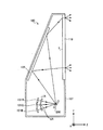
図1は、本発明の実施例1に係る画像表示装置100の概略構成を示す。画像表示装置
100は、スクリーン110の一方の面である被照射面Sにレーザ光を供給し、スクリー
ン110の他方の面から出射される光を観察することで画像を鑑賞する、いわゆるリアプ
ロジェクタである。画像表示装置100は、画像信号に応じて変調されたビーム光をスク
リーン110の被照射面Sにて走査させることにより画像を表示する。
FIG. 1 shows a schematic configuration of an
画像表示装置100は、R光用光源部101Rと、G光用光源部101Gと、B光用光
源部101Bとを有する。R光用光源部101Rは、ビーム光である赤色レーザ光(以下
、「R光」という。)を供給する。G光用光源部101Gは、ビーム光である緑色レーザ
光(以下、「G光」という。)を供給する。B光用光源部101Bは、ビーム光である青
色レーザ光(以下、「B光」という。)を供給する。各色光用光源部101R、101G
、101Bとしては、例えば、面発光型半導体レーザを用いることができる。各色光用光
源部101R、101G、101Bは、それぞれ画像信号に応じて変調された5つのレー
ザ光を供給する。画像信号に応じた変調は、振幅変調、パルス幅変調のいずれを用いても
良い。各色光用光源部101R、101G、101Bからの各色光は、それぞれレンズL
Nを透過した後、単独の走査部200へ入射する。
The
, 101B, for example, a surface emitting semiconductor laser can be used. Each of the color
After passing through N, the light enters the
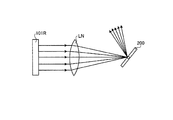
図2は、R光用光源部101Rからの5つのレーザ光を走査部200へ入射させるまで
の構成を説明するものである。画像表示装置100は、R光、G光、B光について同様の
構成を有するため、以下、R光についての構成を代表例として説明を行うこととする。R
光用光源部101Rからの5つのレーザ光は、略等間隔かつ略平行に出射され、レンズL
Nへ入射する。レンズLNは、5つのレーザ光を、走査部200の反射ミラーへ集光する
。R光用光源部101Rからの5つのレーザ光は、レンズLNでの屈折作用により、走査
部200に対してそれぞれ異なる入射角度で入射する。
FIG. 2 illustrates a configuration until five laser beams from the R light source unit 101 </ b> R are incident on the
The five laser beams from the
Incident to N. The lens LN condenses the five laser beams onto the reflection mirror of the
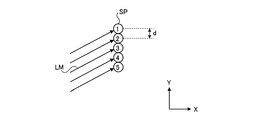
R光用光源部101Rは、図3に示すように、5つのレーザ光のスポットSPが被照射
面Sにおいて第2の方向であるY方向へ並列させるように構成される。なお、画像表示装
置100は、R光用光源部101Rから略平行に出射される複数のレーザ光をレンズLN
により集光させる構成に限られない。例えば、単独のレーザ光を出射させる5つの光源部
を走査部200へ向けて配置する構成としても良い。
As shown in FIG. 3, the R light source unit 101 </ b> R is configured such that five laser beam spots SP are arranged in parallel in the Y direction, which is the second direction, on the irradiated surface S. Note that the
It is not restricted to the structure condensed by. For example, five light source units that emit a single laser beam may be arranged toward the
図4は、走査部200の概略構成を示す。走査部200は、反射ミラー202と、反射
ミラー202の周囲に設けられた外枠部204とを有する、いわゆる二重ジンバル構造を
なしている。外枠部204は、回転軸である第1トーションばね206によって、不図示
の固定部に連結されている。外枠部204は、第1トーションばね206の捩れと、元の
状態への復元とを利用して、第1トーションばね206を中心として回動する。反射ミラ
ー202は、第1トーションばね206に略直交する回転軸である第2トーションばね2
07によって、外枠部204に連結されている。反射ミラー202は、各色光用光源部1
01R、101G、101Bからのレーザ光を反射する。反射ミラー202は、高反射性
の部材、例えばアルミニウムや銀等の金属薄膜を形成することにより構成できる。反射ミ
ラー202は、例えば、正方形形状をなしている。
FIG. 4 shows a schematic configuration of the
07 is connected to the
The laser beams from 01R, 101G, and 101B are reflected. The
反射ミラー202は、外枠部204が第1トーションばね206を中心として回動する
ことにより、スクリーン110においてレーザ光をY方向(図1参照)へ走査させるよう
に変位する。また、反射ミラー202は、第2トーションばね207の捩れと、元の状態
への復元とを利用して、第2トーションばね207を中心として回動する。反射ミラー2
02は、第2トーションばね207を中心として回動することにより、反射ミラー202
で反射したレーザ光をX方向へ走査するように変位する。このように、走査部200は、
各色光用光源部101R、101G、101Bからのレーザ光をX方向とY方向へ繰り返
し走査させる。単独の走査部200を用いる構成とすることで、少ない部品点数で簡易な
構成により各色光を走査させることができる。
The reflecting
02 is rotated around the
The laser beam reflected by is displaced so as to scan in the X direction. Thus, the
Laser light from each color
反射ミラー202は、反射ミラー202の位置におけるレーザ光のスポットと同程度の
サイズで形成されている。上述のようにR光用光源部101Rからの5つのレーザ光は、
反射ミラー202にて集光されることから、レーザ光のスポットと同程度のサイズの反射
ミラー202を用いて、5つのレーザ光を走査させることができる。
The
Since the light is condensed by the
図5は、走査部200を駆動させるための構成を説明するものである。反射ミラー20
2がレーザ光を反射させる側を表側とすると、第1電極301、302は、外枠部204
の裏側の空間であって、第1トーションばね206に関して略対称な位置にそれぞれ設け
られている。第1電極301、302に電圧を印加すると、第1電極301、302と、
外枠部204との間には、電位差に応じた所定の力、例えば静電力が発生する。外枠部2
04は、第1電極301、302に交互に電圧を印加することにより、第1トーションば
ね206を中心として回動する。
FIG. 5 illustrates a configuration for driving the
When the side 2 reflects the laser beam is the front side, the
Are provided at substantially symmetrical positions with respect to the
A predetermined force corresponding to the potential difference, for example, an electrostatic force, is generated between the
04 rotates about the
第2トーションばね207は、詳細には、第3トーションばね307と第4トーション
ばね308とで構成されている。第3トーションばね307と第4トーションばね308
との間には、ミラー側電極305が設けられている。ミラー側電極305の裏側の空間に
は、第2電極306が設けられている。第2電極306に電圧を印加すると、第2電極3
06とミラー側電極305との間には、電位差に応じた所定の力、例えば静電力が発生す
る。第2電極306のいずれにも同位相の電圧を印加すると、反射ミラー202は、第2
トーションばね207を中心として回動する。走査部200は、このようにして反射ミラ
ー202を回動させることで、レーザ光を二次元方向へ走査させる。走査部200は、例
えば、MEMS(Micro Electro Mechanical Systems)技術により作成することができる
。
Specifically, the
A mirror-
A predetermined force corresponding to the potential difference, for example, an electrostatic force, is generated between 06 and the
It rotates around the
走査部200は、例えば画像の1フレーム期間において、副走査方向であるY方向へ1
回レーザ光を走査させる間に、主走査方向であるX方向について複数回レーザ光を往復さ
せるように反射ミラー202を変位させる。X方向を第1の方向、Y方向を第1の方向に
略直交する第2の方向とすると、走査部200は、第1の方向へレーザ光を走査する周波
数が、第2の方向へレーザ光を走査する周波数に比べて高くなるように駆動される。
For example, the
While scanning the laser beam twice, the
例えば、走査部200とスクリーン110との間隔が短い小型な画像表示装置100に
て大型な画像を表示するには、反射ミラー202の偏向角を大きくする必要がある。また
、HDTVの場合、主走査方向についてレーザ光を往復させる場合のレーザ光の走査周波
数は、例えば、33.75kHz、XGAの場合でも例えば24.18kHzとなるため
、反射ミラー202を非常に高速に変位させる必要がある。偏向角を大きくし、かつ高速
な変位を可能とするためには、走査部200は、第2トーションばね207を中心として
反射ミラー202を共振動作させる構成とすることが望ましい。反射ミラー202を共振
動作させることにより、反射ミラー202の変位量を増大させることができる。反射ミラ
ー202の変位量を増大させることにより、走査部200は、少ないエネルギーで効率良
くレーザ光を走査させることができる。
For example, in order to display a large image on the small
反射ミラー202の共振周波数f、反射ミラー202の質量m、及び反射ミラー202
を駆動させるトーションばね207のばね定数kについて、f∝(k/m)1/2の関係が
成り立つ。共振周波数fを高くするためには、質量mを小さくするか、ばね定数kを大き
くする(ばねを硬くする)必要がある。反射ミラー202が大型である場合、質量mが大
きくなるとともにばね定数kを大きくしなければならない。これに対して、トーションば
ね207を硬くする場合、反射ミラー202を変位させるためには非常に大きな駆動力が
必要となることから、反射ミラー202を動作させることが難しくなる。以上から、反射
ミラー202をできるだけ小型とすることが望ましい。
The resonance frequency f of the
With respect to the spring constant k of the
なお、反射ミラー202は、共振動作以外の動作により駆動することとしても良い。走
査部200は、電位差に応じた静電力によって駆動する構成に限られない。例えば、圧電
素子の伸縮力や電磁力を用いて駆動する構成であっても良い。走査部200は、X方向に
レーザ光を走査する反射ミラーと、Y方向にレーザ光を走査する反射ミラーとを設ける構
成としても良い。
The
図1に戻って、走査部200からの光は、反射部105に入射する。反射部105は、
走査部200からのレーザ光をスクリーン110の方向へ反射する。スクリーン110は
、筐体107の正面に設けられている。筐体107は、筐体107内部の空間を密閉する
。スクリーン110は、画像信号に応じて変調されたレーザ光を透過させる透過型スクリ
ーンである。スクリーン110は、例えば、光を観察者側へ角度変換するフレネルレンズ
や、光を拡散させるレンチキュラーレンズ(いずれも不図示。)等を有する。観察者は、
スクリーン110から出射する光を観察することで、画像を鑑賞する。
Returning to FIG. 1, the light from the
The laser beam from the
The image is viewed by observing the light emitted from the
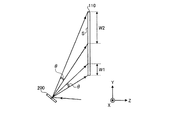
図6は、被照射面S上のY方向についてのレーザ光の走査について説明するものである
。ここでは、反射部105におけるレーザ光の偏向についての図示を省略している。本実
施例の画像表示装置100は、筐体107下部に配置された走査部200からスクリーン
110へ斜めにレーザ光を進行させる構成をなしている。この場合、走査部200から被
照射面Sへの光路は、スクリーン110の下部ほど短く、スクリーン110の上部ほど長
いこととなる。反射ミラー202の偏向角が大きくなるほど、また、走査部200をスク
リーン110に近づけるほど、走査部200からスクリーン110までの光路長の変化量
は大きくなる。
FIG. 6 illustrates scanning of laser light in the Y direction on the irradiated surface S. FIG. Here, the illustration of the deflection of the laser beam in the
YZ平面にてレーザ光を角度θ変位させたとき、レーザ光がスクリーン110上部へ入
射する場合のY方向における走査幅W2は、レーザ光がスクリーン110下部へ入射する
場合のY方向における走査幅W1より大きくなる。このため、反射ミラー202を略等角
速度で変位させても、Y方向についてのレーザ光の走査速度は、スクリーン110の上部
ほど大きく、下部ほど小さくなるように変化してしまう。また、被照射面S上におけるレ
ーザ光同士の間隔は、スクリーン110の上部ほど大きく、下部ほど小さくなる。被照射
面S上の位置によってレーザ光同士の間隔が異なることとなると、画像信号に応じた正確
な画像を表示することが非常に困難となる。
When the laser beam is displaced by the angle θ on the YZ plane, the scanning width W2 in the Y direction when the laser beam is incident on the upper portion of the
そこで、本実施例の画像表示装置100は、5つの同色のレーザ光のうちの1つを、被
照射面S上のY方向について略等速度で走査させる。図7に示すように、Y方向へ並列す
る5つのスポットSP1〜5のうちスポットSP3を形成するレーザ光を主レーザ光LM
とし、主レーザ光LMをY方向について略等速度とする。主レーザ光LMは、第2の方向
であるY方向に並列する5つの同色のレーザ光のうち、Y方向の中央に位置するレーザ光
である。これにより、主レーザ光LMについては、走査部200と被照射面Sとの間の光
路の長さに関わらず、画像信号に応じた正確な位置へ入射させることが可能となる。主レ
ーザ光LM以外の4つのレーザ光については、主レーザ光LMと同じ速度で走査させる。
Therefore, the
And the main laser beam LM is set to approximately the same speed in the Y direction. The main laser beam LM is a laser beam located at the center in the Y direction among the five laser beams of the same color arranged in parallel in the Y direction, which is the second direction. As a result, the main laser light LM can be incident on an accurate position corresponding to the image signal regardless of the length of the optical path between the
5つのレーザ光のうち主レーザ光LMについて略等速度で走査させることで、レーザ光
同士の間隔dのずれを少なくすることができる。但し、走査部200に対する入射角度が
レーザ光ごとに異なるため、走査部200と被照射面Sとの間の光路の長さは、レーザ光
ごとに異なることとなる。このため、走査部200と被照射面Sとの間の光路の長さは、
レーザ光ごとに僅かに異なることとなる。略等速度で走査させる一のレーザ光以外の他の
レーザ光については、画像信号に応じた位置から僅かにずれた位置へ入射することとなる
。
By scanning the main laser beam LM among the five laser beams at a substantially constant speed, it is possible to reduce the deviation of the interval d between the laser beams. However, since the incident angle with respect to the
It will be slightly different for each laser beam. Other laser beams other than the one laser beam scanned at substantially the same speed are incident on a position slightly shifted from the position corresponding to the image signal.
主レーザ光LM以外の他のレーザは、主レーザ光LMから離れた位置を走査するほど、
画像信号に応じた本来の走査線からのずれが大きくなる。Y方向の中央付近に位置するレ
ーザ光を主レーザ光LMとすることで、他のレーザ光の入射位置のずれを少なくすること
ができる。なお、偶数個のレーザ光をY方向へ並列させる場合、仮に、Y方向へ並列する
うちの中心位置にレーザ光が存在するものとし、かかる中心位置のレーザ光が略等速度と
なるように複数のレーザ光を走査させる構成としても良い。また、レーザ光の個数に関わ
らず、Y方向へ並列するうちの中心位置のレーザ光以外のレーザ光を略等速度で走査させ
る構成としても良い。
The other lasers other than the main laser beam LM scan the position away from the main laser beam LM,
The deviation from the original scanning line corresponding to the image signal becomes large. By making the laser beam located in the vicinity of the center in the Y direction the main laser beam LM, it is possible to reduce the deviation of the incident positions of other laser beams. In the case where an even number of laser beams are arranged in parallel in the Y direction, it is assumed that the laser beam exists at the center position of the laser beam in the Y direction, and a plurality of laser beams at the center position have a substantially constant speed. The laser beam may be scanned. Further, a configuration may be adopted in which laser light other than the laser light at the center position among the parallel light beams in the Y direction is scanned at a substantially constant speed regardless of the number of laser light beams.
各色光用光源部は、Y方向へ略等速度で走査させる主レーザ光LMについて、他のレー
ザ光より光量が大きくなるように、5つのレーザ光を供給する。主レーザ光は、例えば、
他のレーザ光に比べて20%以上高い出力とすることができる。略等速度で最も正確な位
置を走査する主レーザ光LMについて他のレーザ光よりも高出力とすることで、画像信号
に応じた画像に近い画像を表示することが可能となる。以上により、走査部200と被照
射面Sとの間の光路長の変化によるレーザ光のずれの影響を最小限とし、解像度の劣化や
輝度の低下を低減することができる。これにより、同色かつ複数のビーム光を走査させ、
画像信号に応じた正確な画像を表示することができるという効果を奏する。
Each color light source unit supplies five laser beams so that the main laser beam LM scanned in the Y direction at a substantially constant speed has a larger light quantity than the other laser beams. The main laser beam is, for example,
The output can be higher by 20% or more than other laser beams. By making the main laser beam LM that scans the most accurate position at substantially the same speed higher than the other laser beams, it is possible to display an image close to an image according to the image signal. As described above, it is possible to minimize the influence of the shift of the laser beam due to the change in the optical path length between the
There is an effect that an accurate image according to the image signal can be displayed.
主レーザ光LM以外の4つのレーザ光については、被照射面Sにおける入射位置が画像
信号に応じた位置から僅かにずれることで、図8に示すように、Y方向へ並列する2つの
画素P1、P2に跨る位置に入射する場合が考えられる。2つの画素P1、P2に跨る位
置にレーザ光が入射する場合の階調は、被照射面Sに形成されるスポットSPのうち画素
と重なる領域の割合で重み付けすることにより決定される。例えば、レーザ光のスポット
SPのうち画素P1と重なる領域AR1の面積と、画素P2と重なる領域AR2の面積と
の比率が3対7であるとする。画像信号に応じて画素P1、画素P2で表現すべき階調が
それぞれM1、M2である場合、レーザ光の階調Mは、以下の式により決定することがで
きる。
M=0.3×M1+0.7×M2
For the four laser beams other than the main laser beam LM, the incident position on the irradiated surface S slightly deviates from the position corresponding to the image signal, so that two pixels P1 arranged in parallel in the Y direction as shown in FIG. , It may be incident on a position straddling P2. The gradation when the laser light is incident on the position straddling the two pixels P1 and P2 is determined by weighting the ratio of the region overlapping the pixel in the spot SP formed on the irradiated surface S. For example, it is assumed that the ratio of the area of the region AR1 that overlaps the pixel P1 in the laser beam spot SP to the area of the region AR2 that overlaps the pixel P2 is 3 to 7. When the gradations to be expressed by the pixels P1 and P2 according to the image signal are M1 and M2, respectively, the gradation M of the laser light can be determined by the following equation.
M = 0.3 × M1 + 0.7 × M2
画素間へレーザ光が入射する場合に、このようにしてレーザ光の階調を変換することで
、画素同士の境目における階調を正確に表現し、正確な画像を表示することができる。ま
た、走査部200と被照射面Sとの間の光路の長さが変化することで、レーザ光同士の間
隔が変化する。例えば、図9に示すように、X方向について第n回目のスキャンをしてい
るレーザ光群SCnのうちのスポットSP5と、第(n+1)回目のスキャンをしている
レーザ光SC群(n+1)のうちのスポットSP1とが、時間差を置いて、重複する部分
を通過することが考えられる。レーザ光同士の間隔が狭くなることでレーザ光同士が重複
すると、斜線を付した重複部分のみが明るくなってしまうこととなる。
When the laser light is incident between the pixels, the gradation of the laser light is converted in this way, so that the gradation at the boundary between the pixels can be accurately expressed and an accurate image can be displayed. Further, the distance between the laser beams changes as the length of the optical path between the
同色かつ複数のレーザ光がY方向について重なり合うように走査する場合に、各色光用
光源部は、スポットSPのうちレーザ光同士が重なり合う領域の割合に応じて光量を変化
させる。例えば、レーザ光同士が重なり合う領域に割合に応じて予め定められた係数を掛
け合わせた光量とすることで、重複部分の明るさを調節することが可能となる。このよう
に、レーザ光の光量を調節することで、レーザ光同士が重複することによる明るさの変化
を低減し、正確な光量分布の画像を表示することができる。
When scanning with the same color and a plurality of laser beams overlapping in the Y direction, each color light source unit changes the amount of light according to the ratio of the regions where the laser beams overlap in the spot SP. For example, it is possible to adjust the brightness of the overlapping portion by setting the amount of light by multiplying a region where the laser beams overlap with a predetermined coefficient according to the ratio. As described above, by adjusting the light amount of the laser light, it is possible to reduce a change in brightness due to the overlap of the laser light and display an image with an accurate light amount distribution.
図10は、レーザ光の走査を制御するためのブロック構成を説明するものである。ここ
では、R、G、Bのうち単独の色光である5つのレーザ光を走査させるための構成を用い
て説明を行う。A/Dコンバータ71は、外部の入力装置等から入力される画像信号をア
ナログ形式からディジタル形式へ変換させる。A/Dコンバータ71でディジタル信号に
変換された映像データは、順次フレームメモリ72に記憶される。
FIG. 10 illustrates a block configuration for controlling the scanning of the laser beam. Here, a description will be given using a configuration for scanning five laser lights, which are individual color lights among R, G, and B. The A /
ROM74は、画像信号に応じた正確な画像を表示するためのデータを格納する。RO
M74には、例えば、主レーザ光LMについて、他のレーザ光より光量を大きくするため
の補正係数が記憶されている。その他、ROM74には、例えば、複数の画素に跨る位置
にレーザ光が入射する場合に階調を変換するための補正係数や、レーザ光同士が重なり合
う場合に光量を変化させるための補正係数が、アドレス情報に関連付けて格納されている
。プロセッサ73は、ROM74に記憶されたデータを用いた演算により、フレームメモ
リ72の映像データを変換する。プロセッサ73では、レーザ光ごとの変調信号の生成と
ともに、ROM74に記憶された補正係数の乗算も行われる。また、プロセッサ73は、
5つのレーザ光により画像を形成するように、各レーザ光への映像データの割り当ても行
う。
The
In M74, for example, a correction coefficient for increasing the light amount of the main laser beam LM as compared with other laser beams is stored. In addition, the
Video data is assigned to each laser beam so that an image is formed by five laser beams.
プロセッサ73からの信号は、レーザ光ごとの5つのラインバッファ75に入力される
。PWM変調部76は、X方向へレーザ光を走査させるラインごとの映像データをライン
バッファ75から読み出し、パルス幅変調のためのパルス信号を生成する。PWM変調部
76からのパルス信号は、レーザダイオードドライバ(以下、「LDD」という。)77
へ出力される。各色光用光源部は、5つのLDD77によりレーザ光を供給する。このよ
うにビーム光供給工程において、プロセッサ73で変換された画像信号を用いて変調され
たレーザ光が供給される。
Signals from the
Is output. Each color light source unit supplies laser light from five LDDs 77. Thus, in the beam light supply step, the laser beam modulated using the image signal converted by the
画像表示装置100は、パルス幅変調によりレーザ光を変調する構成に限られず、振幅
変調によりレーザ光を変調する構成としても良い。この場合、ラインバッファ75からの
信号をさらにD/A変換し、例えばAOM(音響光学素子)によりレーザ光を変調する構
成とすることができる。画像表示装置100は、画像信号をアナログ形式からディジタル
形式へ変換させる構成に限られず、例えば、ディジタル形式からアナログ形式へ変換させ
る構成しても良い。また、ディジタル信号である画像信号を、ディジタル形式の光源変調
用パルス信号に変換することとしても良い。
The
走査部200は、反射ミラー202(図4参照。)に固有の共振周波数で振動するよう
に駆動される。水平走査検知部81は、走査部200により、水平方向であるX方向へレ
ーザ光を走査させるタイミングを検知する。水平走査検知部81としては、例えば、検知
用光源部からの光を検出するフォトセンサを用いることができる。反射ミラー202で反
射させた検知用光源部からの光をフォトセンサで検出することで、反射ミラー202の変
位をモニタすることができる。この他、水平走査検知部81には、例えば、反射ミラー2
02の変位を静電力の変化により検出する静電センサや、回転軸であるトーションばねの
変形度合いにより検出するピエゾ抵抗センサ、電磁アクチュエータによる逆起電力を測定
する構成を用いても良い。
The
An electrostatic sensor that detects the displacement of 02 by a change in electrostatic force, a piezoresistive sensor that detects the degree of deformation of a torsion spring that is a rotating shaft, or a configuration that measures a counter electromotive force by an electromagnetic actuator may be used.
画素クロック生成部82は、水平走査検知部81からの出力に基づいて生成された水平
同期信号、及び演算されたレーザ光の線速から、画素クロックを生成する。画素信号生成
部83は、画素クロックから画素信号を生成する。画素信号は、レーザ光が各画素上を通
るタイミングを知るための信号であって、画像信号に応じて変調されたレーザ光を正確な
位置に入射させるためのものである。垂直同期信号生成部85は、画素クロックから垂直
同期信号を生成する。このようにして、反射ミラー202によりX方向へレーザ光を走査
させるための駆動タイミングに基づいて、垂直方向であるY方向へレーザ光を走査させる
ための同期信号が生成される。PWM変調部76は、画素信号生成部83からの画素信号
、及び垂直同期信号生成部85からの垂直同期信号によりパルス信号のタイミングを決定
する。
The pixel
垂直駆動信号生成部87は、画素クロックから生成された垂直同期信号に基づいて、Y
方向へレーザ光を走査させるための垂直駆動信号を生成する。ここで、垂直駆動信号生成
部87は、垂直同期信号に基づいて、主レーザ光LMが垂直方向について略等速度で走査
するような垂直駆動信号を生成する。垂直駆動部86は、垂直駆動信号生成部87からの
垂直駆動信号に応じて、Y方向へレーザ光を走査させるように反射ミラー202を駆動さ
せる。反射ミラー202は、垂直駆動信号に追従して角速度を変化させることが比較的容
易である。このため、反射ミラー202を変位させる走査部200により、主レーザ光L
Mを略等速度で走査させることができる。以上のようにして、同色かつ複数のレーザ光を
走査させ、画像信号に応じた正確な画像を表示することができる。
The vertical
A vertical drive signal for scanning the laser beam in the direction is generated. Here, the vertical
M can be scanned at approximately the same speed. As described above, the same color and a plurality of laser beams can be scanned to display an accurate image corresponding to the image signal.
次に、本実施例の変形例に係る画像表示装置について説明する。本変形例の画像表示装
置は、第2の方向であるY方向へのレーザ光の走査について、反射ミラー202を略等速
度で変位させる点が、上記の画像表示装置100とは異なる。反射ミラー202を簡単な
等角速度運動をさせれば良いため、走査部200を制御するための構成を簡易かつ低コス
トにできる。本変形例では、Y方向へのレーザ光の走査について、ポリゴンミラーを用い
ても良い。ポリゴンミラーは、複数のミラー片を有する回転体を回転させることで、レー
ザ光を走査させる。ポリゴンミラーを用いることで、さらに簡易な制御が可能となる。
Next, an image display apparatus according to a modification of the present embodiment will be described. The image display apparatus according to the present modification is different from the
本変形例は、2つの画素に跨る位置にレーザ光が入射する場合の階調は、被照射面Sに
形成されるスポットSPのうち画素と重なる領域の割合で重み付けすることにより決定さ
れる点は、上記の画像表示装置100と同様である。これにより、画素同士の境目におけ
る階調を正確に表現し、正確な画像を表示することができる。また、同色かつ複数のレー
ザ光がY方向について重なり合うように走査する場合に、各色光用光源部は、スポットS
Pのうちレーザ光同士が重なり合う領域の割合に応じて光量を変化させる点も、上記の画
像表示装置100と同様である。これにより、レーザ光同士が重複することによる明るさ
の変化を低減し、正確な光量分布の画像を表示することができる。
In the present modification, the gradation when the laser beam is incident on a position straddling two pixels is determined by weighting the ratio of the area overlapping the pixel in the spot SP formed on the irradiated surface S. Is the same as the
The point that the amount of light is changed in accordance with the ratio of the region where the laser beams overlap in P is the same as in the
画像表示装置100は、各色光について5つのレーザ光を供給する構成に限られず、各
色光について複数のレーザ光を供給する構成であれば良い。また、各色光用光源部は、面
発光型半導体レーザを用いる構成に限られず、複数の端面発光型レーザを配列させても良
い。各色光用光源部は、ビーム光を供給可能な構成であれば良く、半導体レーザを用いる
構成に限られない。例えば、各色光用光源部には、固体レーザ、発光ダイオード素子(L
ED)等の固体発光素子のほか、液体レーザやガスレーザを用いる構成としても良い。
The
In addition to a solid state light emitting device such as ED), a liquid laser or a gas laser may be used.
図11は、本発明の実施例2に係る画像表示装置1100の概略構成を示す。画像表示
装置1100は、観察者側に設けられたスクリーン1105にレーザ光を供給し、スクリ
ーン1105で反射する光を観察することで画像を鑑賞する、いわゆるフロント投写型の
プロジェクタである。上記実施例1と同一の部分には同一の符号を付し、重複する説明は
省略する。走査部200からのレーザ光は、出射窓1106を透過した後、スクリーン1
105に入射する。本実施例の場合も、同色かつ複数のレーザ光を走査させ、画像信号に
応じた正確な画像を表示することができる。
FIG. 11 shows a schematic configuration of an
105 is incident. Also in the case of the present embodiment, it is possible to scan the same color and a plurality of laser beams and display an accurate image according to the image signal.
以上のように、本発明に係る画像表示装置は、同色かつ複数のレーザ光を走査させるこ
とにより画像を表示する場合に適している。
As described above, the image display device according to the present invention is suitable for displaying an image by scanning a plurality of laser beams of the same color.
100 画像表示装置、101R R光用光源部、101G G光用光源部、101B
B光用光源部、105 反射部、107 筐体、110 スクリーン、200 走査部
、LN レンズ、S 被照射面、SP スポット、202 反射ミラー、204 外枠部
、206 第1トーションばね、207 第2トーションばね、301、302 第1電
極、305 ミラー側電極、306 第2電極、307 第3トーションばね、308
第4トーションばね、AR1、AR2 領域、P1、P2 画素、SCn、SC(n+1
) レーザ光群、71 A/Dコンバータ、72 フレームメモリ、73 プロセッサ、
75 ラインバッファ、76 PWM変調部、77 LDD、81 水平走査検知部、8
2 画素クロック生成部、83 画素信号生成部、85 垂直同期信号生成部、86 垂
直駆動部、87 垂直駆動信号生成部、1100 画像表示装置、1105 スクリーン
、1106 出射窓
100 image display device, 101R R light source unit, 101G G light source unit, 101B
B light source unit, 105 reflecting unit, 107 housing, 110 screen, 200 scanning unit, LN lens, S irradiated surface, SP spot, 202 reflecting mirror, 204 outer frame unit, 206 first torsion spring, 207 second Torsion spring, 301, 302 1st electrode, 305 Mirror side electrode, 306 2nd electrode, 307 3rd torsion spring, 308
Fourth torsion spring, AR1, AR2 region, P1, P2 pixel, SCn, SC (n + 1)
) Laser light group, 71 A / D converter, 72 frame memory, 73 processor,
75 line buffer, 76 PWM modulator, 77 LDD, 81 horizontal scan detector, 8
2 pixel clock generation unit, 83 pixel signal generation unit, 85 vertical synchronization signal generation unit, 86 vertical drive unit, 87 vertical drive signal generation unit, 1100 image display device, 1105 screen, 1106 exit window
Claims (9)
同色かつ複数の前記ビーム光を供給する光源部と、
前記光源部からの前記ビーム光を、被照射面において第1の方向と、前記第1の方向に
略直交する第2の方向へ走査させる走査部と、を有し、
前記光源部は、前記被照射面において前記第2の方向へ同色かつ複数の前記ビーム光を
並列させるように構成され、
前記走査部は、前記第1の方向へ前記ビーム光を走査させる周波数が、前記第2の方向
へ前記ビーム光を走査させる周波数より高くなるように駆動され、かつ、同色かつ複数の
前記ビーム光のうちの1つを、前記被照射面上の前記第2の方向について略等速度で走査
させることを特徴とする画像表示装置。 An image display device that displays an image with a light beam modulated according to an image signal,
A light source unit for supplying a plurality of the light beams of the same color;
A scanning unit that scans the beam light from the light source unit in a first direction on a surface to be irradiated and a second direction substantially orthogonal to the first direction;
The light source unit is configured to parallelize a plurality of the light beams of the same color in the second direction on the irradiated surface,
The scanning unit is driven so that a frequency at which the light beam is scanned in the first direction is higher than a frequency at which the light beam is scanned in the second direction. One of them is scanned at a substantially constant speed in the second direction on the irradiated surface.
れることを特徴とする請求項1に記載の画像表示装置。 The image display apparatus according to claim 1, wherein the light source unit is configured to collect a plurality of the light beams having the same color and the scanning unit.
2の方向の中央付近に位置するビーム光を、前記被照射面上の前記第2の方向について略
等速度で走査させることを特徴とする請求項1又は2に記載の画像表示装置。 The scanning unit has the same color and a plurality of the light beams arranged in parallel in the second direction, the light beam positioned near the center of the second direction in the second direction on the irradiated surface. The image display apparatus according to claim 1, wherein scanning is performed at a substantially constant speed.
いて、他のビーム光より光量が大きくなるように駆動されることを特徴とする請求項1〜
3のいずれか一項に記載の画像表示装置。 The light source unit is driven so that the light amount of the light beam scanned by the scanning unit in the second direction at a substantially constant speed is larger than that of the other light beams.
4. The image display device according to any one of 3.
する場合に、前記ビーム光により前記被照射面に形成されるスポットのうち前記画素と重
なる領域の割合を用いて重み付けされた階調を表現するように前記ビーム光を変調するこ
とを特徴とする請求項1〜4のいずれか一項に記載の画像表示装置。 When the light beam is incident on a position straddling a plurality of pixels arranged in parallel in the second direction, the light source unit includes a region overlapping with the pixel in a spot formed on the irradiated surface by the light beam. The image display apparatus according to claim 1, wherein the light beam is modulated so as to express a weighted gradation using a ratio.
に走査する場合に、前記ビーム光により前記被照射面に形成されるスポットのうち前記ビ
ーム光同士が重なり合う領域の割合に応じて光量を変化させることを特徴とする請求項1
〜5のいずれか一項に記載の画像表示装置。 When the light source unit scans so that a plurality of the light beams of the same color overlap with each other in the second direction, the light source unit has a region in which the light beams overlap among spots formed on the irradiated surface by the light beam. 2. The amount of light is changed according to the ratio.
The image display apparatus as described in any one of -5.
させることにより、前記ビーム光を走査させることを特徴とする請求項1〜6のいずれか
一項に記載の画像表示装置。 7. The scanning unit according to claim 1, wherein the scanning unit includes a reflection mirror that reflects the beam light, and causes the beam light to scan by causing the reflection mirror to resonate. Image display device.
同色かつ複数の前記ビーム光を供給するビーム光供給工程と、
前記ビーム光を、被照射面において第1の方向と、前記第1の方向に略直交する第2の
方向へ走査させる走査工程と、を含み、
前記走査工程において、前記第1の方向へ前記ビーム光を走査させる周波数が、前記第
2の方向へ前記ビーム光を走査させる周波数より高くなるように駆動され、
前記ビーム光供給工程において、前記被照射面において前記第2の方向へ同色かつ複数
の前記ビーム光を並列させ、かつ、前記第2の方向へ並列する複数の画素に跨る位置に前
記ビーム光が入射する場合に、前記ビーム光により前記被照射面に形成されるスポットの
うち前記画素と重なる領域の割合を用いて重み付けされた階調を表現するように前記ビー
ム光を変調することを特徴とする画像表示方法。 An image display method for displaying an image by beam light modulated in accordance with an image signal,
A light beam supplying step for supplying a plurality of the light beams of the same color;
A scanning step of scanning the beam light in a first direction on a surface to be irradiated and in a second direction substantially orthogonal to the first direction,
In the scanning step, the frequency of scanning the light beam in the first direction is driven to be higher than the frequency of scanning the light beam in the second direction,
In the beam light supplying step, the beam light is arranged in a position across the plurality of pixels parallel to the second direction in the same color and in the second direction on the surface to be irradiated. When incident, the beam light is modulated so as to express a weighted gradation using a ratio of an area overlapping the pixel among spots formed on the irradiated surface by the beam light, Image display method.
同色かつ複数の前記ビーム光を供給するビーム光供給工程と、
前記ビーム光を、被照射面において第1の方向と、前記第1の方向に略直交する第2の
方向へ走査させる走査工程と、を含み、
前記走査工程において、前記第1の方向へ前記ビーム光を走査させる周波数が、前記第
2の方向へ前記ビーム光を走査させる周波数より高くなるように駆動され、
前記ビーム光供給工程において、前記被照射面において前記第2の方向へ同色かつ複数
の前記ビーム光を並列させ、かつ、同色かつ複数の前記ビーム光が前記第2の方向につい
て重なり合うように走査する場合に、前記ビーム光により前記被照射面に形成されるスポ
ットのうち複数の前記ビーム光同士が重なり合う領域の割合に応じて光量を変化させるこ
とを特徴とする画像表示方法。 An image display method for displaying an image by beam light modulated in accordance with an image signal,
A light beam supplying step for supplying a plurality of the light beams of the same color;
A scanning step of scanning the beam light in a first direction on a surface to be irradiated and in a second direction substantially orthogonal to the first direction,
In the scanning step, the frequency of scanning the light beam in the first direction is driven to be higher than the frequency of scanning the light beam in the second direction,
In the beam light supplying step, the same color and a plurality of the beam lights are arranged in parallel in the second direction on the surface to be irradiated, and the same color and the plurality of the beam lights are scanned so as to overlap in the second direction. In this case, the amount of light is changed in accordance with a ratio of a region where a plurality of the light beams overlap among spots formed on the irradiated surface by the light beam.
Priority Applications (1)
| Application Number | Priority Date | Filing Date | Title |
|---|---|---|---|
| JP2005315767A JP2007121802A (en) | 2005-10-31 | 2005-10-31 | Image display device and image display method |
Applications Claiming Priority (1)
| Application Number | Priority Date | Filing Date | Title |
|---|---|---|---|
| JP2005315767A JP2007121802A (en) | 2005-10-31 | 2005-10-31 | Image display device and image display method |
Publications (1)
| Publication Number | Publication Date |
|---|---|
| JP2007121802A true JP2007121802A (en) | 2007-05-17 |
Family
ID=38145699
Family Applications (1)
| Application Number | Title | Priority Date | Filing Date |
|---|---|---|---|
| JP2005315767A Withdrawn JP2007121802A (en) | 2005-10-31 | 2005-10-31 | Image display device and image display method |
Country Status (1)
| Country | Link |
|---|---|
| JP (1) | JP2007121802A (en) |
Cited By (2)
| Publication number | Priority date | Publication date | Assignee | Title |
|---|---|---|---|---|
| WO2010047147A1 (en) * | 2008-10-24 | 2010-04-29 | 株式会社日立製作所 | Semiconductor laser module and method for manufacturing the same |
| WO2016203991A1 (en) * | 2015-06-19 | 2016-12-22 | ソニー株式会社 | Projection device, projection module, and electronic device |
-
2005
- 2005-10-31 JP JP2005315767A patent/JP2007121802A/en not_active Withdrawn
Cited By (6)
| Publication number | Priority date | Publication date | Assignee | Title |
|---|---|---|---|---|
| WO2010047147A1 (en) * | 2008-10-24 | 2010-04-29 | 株式会社日立製作所 | Semiconductor laser module and method for manufacturing the same |
| WO2016203991A1 (en) * | 2015-06-19 | 2016-12-22 | ソニー株式会社 | Projection device, projection module, and electronic device |
| CN107710047A (en) * | 2015-06-19 | 2018-02-16 | 索尼公司 | Projection arrangement, projection module and electronic instrument |
| JPWO2016203991A1 (en) * | 2015-06-19 | 2018-04-05 | ソニー株式会社 | Projection apparatus, projection module, and electronic apparatus |
| US10564436B2 (en) | 2015-06-19 | 2020-02-18 | Sony Corporation | Projecting apparatus, projecting module, and electronic instrument |
| JP7062952B2 (en) | 2015-06-19 | 2022-05-09 | ソニーグループ株式会社 | Projection devices, projection modules and electronic devices |
Similar Documents
| Publication | Publication Date | Title |
|---|---|---|
| CN100394247C (en) | Optical scanning device, its control method, and image display device | |
| JP4161971B2 (en) | Optical scanning device and image display device | |
| JP5083452B2 (en) | Optical scanning device, optical scanning device control method, and image display device | |
| JP2008509448A (en) | 2D image projection system | |
| JPWO2012111698A1 (en) | Scanning image display apparatus and image display method thereof | |
| JP4929738B2 (en) | Optical scanning device, optical scanning device control method, and image display device | |
| JP4501811B2 (en) | Optical scanning device and image display device | |
| JP6485013B2 (en) | Optical deflector, image display device, and object device | |
| JP2007293226A (en) | Laser display apparatus | |
| JP2007047243A (en) | Image display device and control method of image display device | |
| JP2007025522A (en) | Image display device and control method of image display device | |
| US7810933B2 (en) | Image projection apparatus | |
| JP4998640B2 (en) | Image display device | |
| JP2007140010A (en) | Image display device | |
| JP4852971B2 (en) | Image display device | |
| JP2007140009A (en) | Image display device | |
| JP4910321B2 (en) | Image display device and control method of image display device | |
| JP4645154B2 (en) | Image display device | |
| JP2007025191A (en) | Image display device and control method of image display device | |
| JP6134494B2 (en) | Laser beam display device and mirror control method thereof | |
| JP4670451B2 (en) | Optical scanning device, optical scanning device control method, and image display device | |
| JP4826731B2 (en) | Image display device | |
| JP2007121539A (en) | Image display device | |
| JP2007079087A (en) | Image display device and control method of image display device | |
| JP4710353B2 (en) | Optical scanning device and image display device |
Legal Events
| Date | Code | Title | Description |
|---|---|---|---|
| RD04 | Notification of resignation of power of attorney |
Free format text: JAPANESE INTERMEDIATE CODE: A7424 Effective date: 20070405 |
|
| A300 | Withdrawal of application because of no request for examination |
Free format text: JAPANESE INTERMEDIATE CODE: A300 Effective date: 20090106 |