JP2007149162A - Optical disk recording/reproducing device - Google Patents
Optical disk recording/reproducing device Download PDFInfo
- Publication number
- JP2007149162A JP2007149162A JP2005338655A JP2005338655A JP2007149162A JP 2007149162 A JP2007149162 A JP 2007149162A JP 2005338655 A JP2005338655 A JP 2005338655A JP 2005338655 A JP2005338655 A JP 2005338655A JP 2007149162 A JP2007149162 A JP 2007149162A
- Authority
- JP
- Japan
- Prior art keywords
- layer
- optical
- optical disk
- light
- optical disc
- Prior art date
- Legal status (The legal status is an assumption and is not a legal conclusion. Google has not performed a legal analysis and makes no representation as to the accuracy of the status listed.)
- Pending
Links
- 230000003287 optical effect Effects 0.000 title claims abstract description 347
- 238000000034 method Methods 0.000 claims abstract description 41
- 239000010410 layer Substances 0.000 claims description 70
- 239000002356 single layer Substances 0.000 claims description 54
- 238000010586 diagram Methods 0.000 description 4
- 238000000926 separation method Methods 0.000 description 4
- 238000001514 detection method Methods 0.000 description 3
- 239000002355 dual-layer Substances 0.000 description 3
- 230000005236 sound signal Effects 0.000 description 3
- 230000006870 function Effects 0.000 description 2
- 238000006243 chemical reaction Methods 0.000 description 1
- 230000001678 irradiating effect Effects 0.000 description 1
- 238000004886 process control Methods 0.000 description 1
Images


Landscapes
- Optical Recording Or Reproduction (AREA)
- Optical Head (AREA)
Abstract
Description
本発明は、少なくとも2種の波長の異なるレーザ光を出射できる光ピックアップを備え、1層の光ディスクまたは2層の光ディスクに対して情報の記録/再生を行うことが可能な光ディスク記録再生装置に関し、特に、1層の光ディスクと2層の光ディスクとの判別を行う際のディスク判別処理に関する。 The present invention relates to an optical disc recording / reproducing apparatus that includes an optical pickup capable of emitting at least two types of laser beams having different wavelengths and that can record / reproduce information with respect to a single-layer optical disc or a dual-layer optical disc. In particular, the present invention relates to a disc discrimination process when discriminating between a single-layer optical disc and a double-layer optical disc.
従来から光ディスク記録再生装置は、挿入されている光ディスクの種類の判別を行うためのディスク判別機能を有し、ディスク規格で定められているリードインゾーン(Lead In Zone)のディスク情報もしくはアドレス情報を読み出し後に、そのディスク情報もしくはアドレス情報から論理的に2層の光ディスクであるか1層の光ディスクであるかを判別している。 Conventionally, an optical disc recording / reproducing apparatus has a disc discriminating function for discriminating the type of an inserted optical disc, and uses disc information or address information of a lead-in zone defined by the disc standard. After reading, it is discriminated from the disc information or address information whether the disc is logically a two-layer optical disc or a single-layer optical disc.
例えば、特許文献1に記載の光ディスク記録再生装置では、挿入された光ディスクから得られる少なくとも2つの制御信号(再生信号とフォーカス信号とを含む制御信号、再生信号とトラッキングエラー信号とを含む制御信号、フォーカスエラー信号とトラッキングエラー信号とを含む制御信号、フォーカスエラー信号のレベルとフォーカスエラー信号のSカーブの数とを含む制御信号、フォーカスオン信号とトラッキングエラー信号とを含む制御信号、あるいはトラッキングエラー信号のオフセット量とトラッキングエラー信号のレベルとを含む制御信号)をそれぞれ検出する第1および第2の信号検出手段と、前記第1および第2の信号検出手段の検出結果に応じて、挿入された光ディスクの種類を判別する判別手段とが備えられ、挿入された光ディスクの種類(DVD−S(1層ディスク)、DVD−D(2層ディスク)、CD、CD−R)を判別するようにしている。
For example, in the optical disc recording / reproducing apparatus described in
また、特許文献2に記載の光学的記録媒体の識別装置は、トラッキングサーボのオフ状態において第1光ピックアップもしくは第2の光ピックアップにより検知されるトラッキングエラー信号のオフセットの有無もしくは大小を判別する判別手段を備え、挿入された光ディスクの種類(CDと片面記録SDもしくは両面記録・片面読出SDもしくは片面記録の高密度SDもしくは両面記録・片面読出の高密度SD)を判別するようにしている。
Further, the optical recording medium identifying device described in
また、特許文献3に記載の光ディスク記録再生装置は、挿入された光ディスク表面でのレーザ光の反射量に基づいて生成される和信号とフォーカスエラー信号を、波長の異なるレーザ光のそれぞれに対して検出し、これら検出した波長の異なるレーザ光による前記和信号とフォーカスエラー信号とにより、前記挿入された光ディスクの種類(DVD−RAM、DVD−ROM(2層)、CD−R、DVD−ROM(1層)、CD−ROM、CD−R)を判別するようにしている。また、挿入された光ディスク表面でのレーザ光の反射量に基づいて生成されるフォーカスエラー信号のゼロクロスの回数に基づいて、前記挿入された光ディスクの種類を判別するようにしている。
しかしながら、特許文献1に記載の光ディスク記録再生装置では、挿入された光ディスクから得られる少なくとも2つの制御信号をそれぞれ検出し、この検出結果に応じて、挿入された光ディスクの種類を判別するようにしているので、光ディスクの種類を判別するための少なくとも2つの制御信号が必要になるが、それらの2つの制御信号は、光ディスクを挿入した後のマウント処理が最後まで行わないと取り出せないし、特に、2層の光ディスク(DVD−D)を判別するのに、1層目の記録面からの反射光による信号と2層目の記録面からの反射光による信号との平均の値を判別データとして用いているが、この判別データを生成するのに、1層目の記録面と2層目の記録面の両面にレーザビーム(レーザ光)を照射させなければならないので、光ピックアップの制御やディスク判別の処理が複雑化し、ディスク判別の処理時間も多くかかるという課題が生じる。
However, the optical disc recording / reproducing apparatus described in
また、特許文献2に記載の光学的記録媒体の識別装置では、トラッキングサーボのオフ状態において第1光ピックアップもしくは第2光ピックアップにより検知されるトラッキングエラー信号のオフセットの有無もしくは大小を判別して光ディスクの種類を判別しているが、2層の光ディスクの判別については開示されていない。
Further, in the optical recording medium identification device described in
また、特許文献3に記載の光ディスク記録再生装置は、挿入された光ディスクの種類を判別するのに、挿入された光ディスク表面でのレーザ光の反射量に基づいて生成される和信号とフォーカスエラー信号を、波長の異なるレーザ光のそれぞれに対して検出し、これら検出した波長の異なるレーザ光による前記和信号とフォーカスエラー信号により、前記挿入された光ディスクの種類を判別するようにしているので、特に、2層の光ディスクを判別するのに、1層目の記録面と2層目の記録面の両面にレーザ光を照射させなければならず、ディスク判別の処理が複雑化し、判別処理時間も多くかかるという課題が生じる。
In addition, the optical disc recording / reproducing apparatus described in
本発明は、上記のような課題を解決するためになされたもので、簡単な処理で2層の光ディスクであるか1層の光ディスクであるかを判別することができるディスク判別機能を有する光ディスク記録再生装置を提供することを目的とする。 The present invention has been made to solve the above-described problems, and an optical disc recording having a disc discrimination function capable of discriminating between a two-layer optical disc and a single-layer optical disc by a simple process. An object is to provide a playback device.
上記目的を達成するために、請求項1の発明は、少なくとも2種の波長の異なるレーザ光を出射できる光ピックアップを備え、1層の光ディスクまたは2層の光ディスクに対して情報の記録/再生を行うことが可能な光ディスク記録再生装置において、光ディスクが挿入され、マウント処理が開始して、この光ディスクの記録面に対して1層用レーザ光のフォーカスを合わせるフォーカスオン状態で1層用レーザ光を出射させるように前記光ピックアップを制御する光ピックアップ制御手段と、前記1層用レーザ光が前記フォーカスオン状態で光ディスクの記録面に照射されて反射された反射光のうち前記光ピックアップのメイン受光部から漏れた漏れ光の一部を前記光ピックアップのサブ受光部で受光して得られた前記光ピックアップからのサブトラッキングエラー信号を測定して、そのサブトラッキングエラー信号のオフセットが閾値以上であるか否かを判定するオフセット判定手段と、前記オフセットが閾値以上であると判定された場合は挿入されている光ディスクを2層の光ディスクであると判定し、前記オフセットが閾値未満であると判定された場合は挿入されている光ディスクを1層の光ディスクであると判定するディスク判定手段とを有するシステムコントローラを備えたことを特徴とする光ディスク記録再生装置を提供する。
In order to achieve the above object, the invention of
この構成において、光ディスクが挿入され、マウント処理が開始すると、光ピックアップ制御手段は、光ディスクの記録面に対して1層用レーザ光のフォーカスを合わせるため、1層用レーザ光をフォーカスオンの状態にする。このフォーカスオン状態において、オフセット判定手段は、前記1層用レーザ光が光ディスクの記録面に照射されて反射された反射光のうち光ピックアップのメイン受光部から漏れた漏れ光の一部を光ピックアップのサブ受光部で受光して得られた光ピックアップからのサブトラッキングエラー信号を測定して、そのオフセットが閾値以上であるか否かを判定する。ディスク判定手段は、前記オフセットが閾値以上であると判定された場合は、挿入されている光ディスクを2層の光ディスクであると判定し、前記オフセットが閾値未満であると判定された場合は、挿入されている光ディスクを1層の光ディスクであると判定する。 In this configuration, when the optical disk is inserted and the mounting process is started, the optical pickup control means brings the single-layer laser light into a focus-on state in order to focus the single-layer laser light on the recording surface of the optical disk. To do. In this focus-on state, the offset determination means optically picks up a part of the leaked light leaked from the main light receiving part of the optical pickup out of the reflected light that is reflected when the recording light of the optical disk is irradiated onto the recording surface of the optical disc. The sub-tracking error signal from the optical pickup obtained by receiving the light at the sub-light receiving unit is measured, and it is determined whether or not the offset is equal to or greater than a threshold value. The disc determination means determines that the inserted optical disc is a two-layer optical disc when it is determined that the offset is equal to or greater than a threshold value, and inserts when the offset is determined to be less than the threshold value. The optical disc being used is determined to be a single-layer optical disc.
この構成によれば、1層用レーザ光が光ディスクの記録面に照射されて反射された反射光のうち光ピックアップのメイン受光部から漏れた漏れ光の一部を光ピックアップのサブ受光部で受光して得られた光ピックアップからのサブトラッキングエラー信号のオフセットが閾値以上であるか否かを判定することにより、挿入されている光ディスクが2層の光ディスクであるか1層の光ディスクであるかの判定を行うようにしたので、光ディスクのリードインゾーンのディスク情報もしくはアドレス情報の読み取り前に、即ちマウント処理が終了するまでに、挿入されている光ディスクが2層の光ディスクであるか1層の光ディスクであるかを簡単な処理で判別することができ、これにより、挿入されている光ディスクに応じた設定処理が早くでき、この結果、挿入されている光ディスクに対して記録または再生を早く開始させることができる。 According to this configuration, a part of the leaked light leaked from the main light receiving portion of the optical pickup out of the reflected light that is reflected when the recording surface of the optical disk is irradiated with the laser light for one layer is received by the sub light receiving portion of the optical pickup. By determining whether or not the offset of the sub-tracking error signal from the optical pickup obtained in this way is greater than or equal to a threshold value, whether the inserted optical disk is a two-layer optical disk or a single-layer optical disk Since the determination is made, the optical disk inserted is a double-layer optical disk or a single-layer optical disk before reading the disk information or address information in the lead-in zone of the optical disk, that is, before the mounting process is completed. Can be determined by simple processing, which makes setting processing according to the inserted optical disk faster. As a result, it is possible to start earlier recording or reproducing the optical disc being inserted.
請求項2の発明は、少なくとも2種の波長の異なるレーザ光を出射できる光ピックアップを備え、1層の光ディスクまたは2層の光ディスクに対して情報の記録/再生を行うことが可能な光ディスク記録再生装置において、光ディスクが挿入され、マウント処理が開始して、この光ディスクの記録面に対して1層用レーザ光のフォーカスを合わせるフォーカスオン状態で1層用レーザ光を前記光ピックアップから出射させ、前記1層用レーザ光が前記フォーカスオン状態で光ディスクの記録面に照射されて反射された反射光のうちの漏れ光を受光して得られた前記光ピックアップからのサブトラッキングエラー信号を測定し、そのサブトラッキングエラー信号のオフセットが、閾値以上であれば挿入されている光ディスクを2層の光ディスクであると判定し、閾値未満であれば挿入されている光ディスクを1層の光ディスクであるという判定を行うシステムコントローラを備えたことを特徴とする光ディスク記録再生装置を提供する。 According to a second aspect of the present invention, there is provided an optical pickup capable of emitting at least two types of laser beams having different wavelengths, and an optical disc recording / reproducing capable of recording / reproducing information on a single-layer optical disc or a dual-layer optical disc. In the apparatus, the optical disk is inserted, the mounting process is started, and the single-layer laser light is emitted from the optical pickup in a focus-on state in which the focus of the single-layer laser light is focused on the recording surface of the optical disk. Measuring a sub-tracking error signal from the optical pickup obtained by receiving leakage light of reflected light that is reflected when the laser light for one layer is irradiated and reflected on the recording surface of the optical disc in the focus-on state; If the offset of the sub-tracking error signal is equal to or greater than the threshold value, the inserted optical disk is replaced with a two-layer optical disk. Determines that, to provide an optical disk recording and reproducing apparatus characterized by comprising a system controller for determining that the optical disk has been inserted is less than the threshold value is an optical disk of the first layer.
この構成において、光ディスクが挿入され、マウント処理が開始して、この光ディスクの記録面に対してフォーカスオン状態で光ピックアップから1層用レーザ光を出射させると、1層用レーザ光が光ディスクの記録面に照射されて、反射された反射光のうちの漏れ光が光ピックアップで受光され、この漏れ光によるサブトラッキングエラー信号のオフセットが、閾値以上であれば、挿入されている光ディスクは2層の光ディスクであると判定され、閾値未満であれば、挿入されている光ディスクは1層の光ディスクであると判定される。 In this configuration, when the optical disk is inserted, the mounting process is started, and the single-layer laser light is emitted from the optical pickup in a focus-on state with respect to the recording surface of the optical disk, the single-layer laser light is recorded on the optical disk. Of the reflected light that is irradiated onto the surface, the leaked light is received by the optical pickup, and if the offset of the sub-tracking error signal due to the leaked light is greater than or equal to the threshold value, the inserted optical disk has two layers. If it is determined that the optical disk is an optical disk and is less than the threshold value, it is determined that the inserted optical disk is a single-layer optical disk.
この構成によれば、1層用レーザ光が光ディスクの記録面に照射されて反射された反射光のうちの漏れた漏れ光を光ピックアップで受光して得られたサブトラッキングエラー信号のオフセットが閾値以上であるか否かを判定することにより、挿入されている光ディスクが2層の光ディスクであるか1層の光ディスクであるのかの判定を行うようにしたので、光ディスクのリードインゾーンのディスク情報もしくはアドレス情報の読み取り前に、即ちマウント処理が終了するまでに、挿入されている光ディスクが2層の光ディスクであるか1層の光ディスクであるかを簡単な処理で判別することができ、これにより、挿入されている光ディスクに応じた設定処理が早くでき、この結果、挿入されている光ディスクに対して記録または再生を早く開始させることができる。 According to this configuration, the offset of the sub-tracking error signal obtained by receiving the leaked leaked light of the reflected light that is reflected by irradiating the recording surface of the optical disc with the single-layer laser light is the threshold value. By determining whether or not the above is true, it is determined whether the inserted optical disk is a two-layer optical disk or a single-layer optical disk. Before reading the address information, that is, before the mounting process is completed, it is possible to determine whether the inserted optical disk is a two-layer optical disk or a single-layer optical disk by a simple process. The setting process corresponding to the inserted optical disk can be performed quickly, and as a result, recording or reproduction can be performed quickly on the inserted optical disk. It can be started.
請求項3の発明では、請求項2の発明において、前記1層用レーザ光が前記フォーカスオン状態で光ディスクの記録面に照射されて反射された反射光のうちの漏れ光を受光して得られた前記光ピックアップからのサブトラッキングエラー信号とは、前記1層用レーザ光が前記フォーカスオン状態で光ディスクの記録面に照射されて反射された反射光のうち前記光ピックアップのメイン受光部から漏れた漏れ光の一部を前記光ピックアップのサブ受光部で受光して得られた前記光ピックアップからのサブトラッキングエラー信号であるので、前記光ピックアップのサブ受光部からのサブトラッキングエラー信号を用いれば、挿入されている光ディスクが2層の光ディスクであるか1層の光ディスクであるかの判定を簡単な処理で行うことができるようになる。 According to a third aspect of the present invention, in the second aspect of the invention, the first layer laser light is obtained by receiving leakage light of reflected light that is reflected when the recording surface of the optical disk is irradiated in the focus-on state. The sub-tracking error signal from the optical pickup leaks from the main light receiving portion of the optical pickup out of the reflected light that is reflected when the laser light for the first layer is irradiated onto the recording surface of the optical disc in the focus-on state. Since it is a sub-tracking error signal from the optical pickup obtained by receiving a part of the leakage light by the sub-light receiving unit of the optical pickup, if a sub-tracking error signal from the sub-light receiving unit of the optical pickup is used, Whether the inserted optical disk is a two-layer optical disk or a single-layer optical disk can be determined with a simple process. So as to.
請求項4の発明では、請求項2の発明において、前記システムコントローラは、光ディスクが挿入され、マウント処理が開始して、この光ディスクの記録面に対して1層用レーザ光のフォーカスを合わせるフォーカスオン状態で1層用レーザ光を出射させるように前記光ピックアップを制御する光ピックアップ制御手段と、前記1層用レーザ光が前記フォーカスオン状態で光ディスクの記録面に照射されて反射された反射光のうち前記光ピックアップのメイン受光部から漏れた漏れ光の一部を前記光ピックアップのサブ受光部で受光して得られた前記光ピックアップからのサブトラッキングエラー信号を測定して、そのサブトラッキングエラー信号のオフセットが閾値以上であるか否かを判定するオフセット判定手段と、前記オフセットが閾値以上であると判定された場合は挿入されている光ディスクを2層の光ディスクであると判定し、前記オフセットが閾値未満であると判定された場合は挿入されている光ディスクを1層の光ディスクであると判定するディスク判定手段とを有する。 According to a fourth aspect of the present invention, in the second aspect of the present invention, the system controller is configured to focus on the single-layer laser beam to be focused on the recording surface of the optical disk after the optical disk is inserted and the mounting process is started. Optical pickup control means for controlling the optical pickup so as to emit laser light for one layer in a state, and reflected light reflected from the recording surface of the optical disk irradiated with the laser light for one layer in the focus-on state. The sub-tracking error signal is measured by measuring the sub-tracking error signal from the optical pickup obtained by receiving a part of the leaked light from the main light-receiving unit of the optical pickup by the sub-light-receiving unit of the optical pickup. Offset determining means for determining whether or not the offset is greater than or equal to a threshold, and the offset is a threshold If it is determined that the optical disc is determined to be above, the inserted optical disc is determined to be a two-layer optical disc. If the offset is determined to be less than the threshold value, the inserted optical disc is a single-layer optical disc. Disc judging means for judging that.
したがって、前記システムコントローラは、光ピックアップ制御処理、オフセット判定処理、およびディスク判定処理を実現でき、これにより、サブトラッキングエラー信号のオフセットが閾値以上であるか否かの判定を行うことができ、挿入されている光ディスクが2層の光ディスクであるか1層の光ディスクであるかの判定を行うことが可能になる。 Therefore, the system controller can realize the optical pickup control process, the offset determination process, and the disk determination process, thereby determining whether or not the offset of the sub-tracking error signal is greater than or equal to the threshold value, and inserting It is possible to determine whether the optical disc being used is a two-layer optical disc or a single-layer optical disc.
以上のように本発明によれば、少なくとも2種の波長の異なるレーザ光を出射できる光ピックアップを備え、1層の光ディスクまたは2層の光ディスクに対して情報の記録/再生を行うことが可能な光ディスク記録再生装置において、光ディスクが挿入され、マウント処理が開始して、この光ディスクの記録面に対して1層用レーザ光のフォーカスを合わせるフォーカスオン状態で1層用レーザ光を出射させるように前記光ピックアップを制御する光ピックアップ制御手段と、前記1層用レーザ光が前記フォーカスオン状態で光ディスクの記録面に照射されて反射された反射光のうち前記光ピックアップのメイン受光部から漏れた漏れ光の一部を前記光ピックアップのサブ受光部で受光して得られた前記光ピックアップからのサブトラッキングエラー信号を測定して、そのサブトラッキングエラー信号のオフセットが閾値以上であるか否かを判定するオフセット判定手段と、前記オフセットが閾値以上であると判定された場合は挿入されている光ディスクを2層の光ディスクであると判定し、前記オフセットが閾値未満であると判定された場合は挿入されている光ディスクを1層の光ディスクであると判定するディスク判定手段とを有するシステムコントローラを備えたので、光ディスクのリードインゾーンのディスク情報もしくはアドレス情報の読み取り前に、即ちマウント処理が終了するまでに、挿入されている光ディスクが2層の光ディスクであるか1層の光ディスクであるかを簡単な処理で判別することができ、これにより、挿入されている光ディスクに応じた設定処理が早くでき、この結果、挿入されている光ディスクに対して記録または再生を早く開始させることができる。 As described above, according to the present invention, an optical pickup capable of emitting at least two types of laser beams having different wavelengths is provided, and information can be recorded / reproduced with respect to a single-layer optical disk or a double-layer optical disk. In the optical disc recording / reproducing apparatus, the optical disc is inserted, the mounting process is started, and the single layer laser beam is emitted in a focus-on state in which the focus of the single layer laser beam is focused on the recording surface of the optical disc. Optical pickup control means for controlling the optical pickup, and leakage light leaked from the main light receiving portion of the optical pickup out of the reflected light that is reflected when the first layer laser light is irradiated onto the recording surface of the optical disc in the focus-on state. Sub-tracking from the optical pickup obtained by receiving a part of the optical pickup by the sub-light-receiving portion of the optical pickup An error determination unit that measures an error signal and determines whether or not the offset of the sub-tracking error signal is equal to or greater than a threshold value, and two optical disks that are inserted when the offset is determined to be equal to or greater than the threshold value. A disc controller for discriminating that the inserted optical disc is a single-layer optical disc when it is determined that the optical disc is a single-layer optical disc. A simple process determines whether the inserted optical disk is a two-layer optical disk or a single-layer optical disk before reading the disk information or address information in the lead-in zone of the optical disk, that is, before the mounting process is completed. This makes it possible to perform setting processing according to the inserted optical disk. Kudeki, this result can be started earlier recording or reproducing the optical disc being inserted.
また、本発明によれば、少なくとも2種の波長の異なるレーザ光を出射できる光ピックアップを備え、1層の光ディスクまたは2層の光ディスクに対して情報の記録/再生を行うことが可能な光ディスク記録再生装置において、光ディスクが挿入され、マウント処理が開始して、この光ディスクの記録面に対して1層用レーザ光のフォーカスを合わせるフォーカスオン状態で1層用レーザ光を前記光ピックアップから出射させ、前記1層用レーザ光が前記フォーカスオン状態で光ディスクの記録面に照射されて反射された反射光のうちの漏れ光を受光して得られた前記光ピックアップからのサブトラッキングエラー信号を測定し、そのサブトラッキングエラー信号のオフセットが、閾値以上であれば挿入されている光ディスクを2層の光ディスクであると判定し、閾値未満であれば挿入されている光ディスクを1層の光ディスクであるという判定を行うシステムコントローラを備えたので、光ディスクのリードインゾーンのディスク情報もしくはアドレス情報の読み取り前に、即ちマウント処理が終了するまでに、挿入されている光ディスクが2層の光ディスクであるか1層の光ディスクであるかを簡単な処理で判別することができ、これにより、挿入されている光ディスクに応じた設定処理が早くでき、この結果、挿入されている光ディスクに対して記録または再生を早く開始させることができる。 According to the present invention, there is provided an optical pickup capable of emitting at least two types of laser beams having different wavelengths, and optical disc recording capable of recording / reproducing information on a single-layer optical disc or a dual-layer optical disc. In the reproducing apparatus, the optical disk is inserted, the mounting process is started, and the single-layer laser light is emitted from the optical pickup in a focus-on state in which the focus of the single-layer laser light is focused on the recording surface of the optical disk. Measuring the sub-tracking error signal from the optical pickup obtained by receiving the leakage light of the reflected light that is reflected when the recording light of the optical disk is irradiated and reflected on the recording surface of the optical disc in the focus-on state, If the offset of the sub-tracking error signal is equal to or greater than the threshold, the inserted optical disk is A system controller that determines that the inserted optical disk is a single-layer optical disk if it is less than the threshold, before reading disk information or address information in the lead-in zone of the optical disk. That is, before the mounting process is completed, it is possible to determine whether the inserted optical disk is a two-layer optical disk or a single-layer optical disk by a simple process. The corresponding setting process can be performed quickly, and as a result, recording or reproduction can be started quickly with respect to the inserted optical disk.
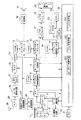
以下、添付図面を参照しつつ、本発明の実施の形態について説明する。図1は本発明の一実施形態に係る光ディスク記録再生装置の構成を示すブロック図である。 Hereinafter, embodiments of the present invention will be described with reference to the accompanying drawings. FIG. 1 is a block diagram showing a configuration of an optical disc recording / reproducing apparatus according to an embodiment of the present invention.
この光ディスク記録再生装置は、装置全体を制御するシステムコントローラ22と、光ディスク1を回転させるスピンドルモータ5と、少なくとも2種の波長の異なるレーザ光を出射でき、光ディスク1に対して情報の書き込み/読み出しを光学的に行う光ピックアップ2と、この光ピックアップ2を光ディスク1の半径方向に移動させるためのスレッド3と、システムコントローラ22の指示に応じて、モータ駆動回路34を介してスピンドルモータ5、およびスレッド3を駆動すると共に、光ピックアップ2に内蔵された対物レンズ(図示せず)を動かすことによりレーザ光の焦点位置を光ディスク1の記録面に対して垂直方向および水平方向に移動させる制御を行ったり、光ピックアップ2のチルト制御を行ったりするサーボ制御部4とを備えている。
This optical disk recording / reproducing apparatus can emit a laser beam having at least two kinds of wavelengths and a
また、この光ディスク記録再生装置は、光ディスク1の再生時に光ピックアップ2からの読取信号であるRF信号を増幅するRFアンプ6と、このRFアンプ6から出力されたRF信号をデジタルデータに変換した後に光ディスク1のデータフォーマットに応じた信号復調処理と誤り訂正処理を行って生成したデータを再生用バッファメモリとしてのRAM7に格納するデジタル信号処理部8と、システムコントローラ22の指示に応じてデジタル信号処理部8から出力されたデータストリームの中からオーディオデータとサブピクチャデータとビデオデータとを分離するストリーム分離部9とを備えている。
The optical disc recording / reproducing apparatus also amplifies an RF signal which is a read signal from the
また、この光ディスク記録再生装置は、ストリーム分離部9から出力されたオーディオデータを入力して所定のデコード処理を行うオーディオデコーダ11と、このオーディオデコーダ11でのデコード処理を行うためにデータを一時的に格納するRAM10と、ストリーム分離部9から出力されたサブピクチャデータを入力して所定のデコード処理を行うサブピクチャデコーダ13と、このサブピクチャデコーダ13でのデコード処理を行うためにデータを一時的に格納するRAM12と、ストリーム分離部9から出力されたビデオデータを入力してMPEG(Moving Picture Experts Group)でデコード処理を行うビデオMPEGデコーダ15と、このビデオMPEGデコーダ15でのデコード処理を行うためにデータを一時的に格納するRAM14とを備えている。
The optical disc recording / reproducing apparatus also receives an
また、この光ディスク記録再生装置は、システムコントローラ22の指示に応じてビデオMPEGデコーダ15から出力されたデータとサブピクチャデコーダ13から出力されたデータとを合成するビデオプロセッサ17と、このビデオプロセッサ17から出力された合成データを表示用のビデオ信号に変換して画像をディスプレイ装置20に表示させるビデオエンコーダ18と、オーディオデコーダ11から出力されたデータをアナログのオーディオ信号に変換して図示しない音声回路を介して例えばスピーカ19に供給するD/A変換器16とを備えている。
The optical disk recording / reproducing apparatus also includes a
また、この光ディスク記録再生装置は、システムコントローラ22に対して、記録指示を与えるための記録キー、再生指示を与えるための再生キー、記録や再生の停止指示を与えるための停止キー、電源キーなど各種操作キーを有するリモコン21とを備えている。また、この光ディスク記録再生装置は、装置の各構成要素を制御したり、装置全体を制御したりするためのプログラムやデータが記憶されたフラッシュROM23と、このフラッシュROM23のプログラムやデータに従って演算処理を行いシステムコントローラ22を制御するCPU24と、このCPU24の演算処理に必要なデータを一時的に格納するRAM27とを備えている。
The optical disc recording / reproducing apparatus also has a recording key for giving a recording instruction to the
また、この光ディスク記録再生装置は、アンテナ28に接続されるチューナ29と、このチューナ29で選局されたテレビジョン放送のアナログの映像音声信号、あるいは図示しないテレビジョン受信機や他の映像音声出力機器からの映像音声信号をデジタルの映像音声データに変換するA/D変換回路30と、前記映像音声データをMPEGでエンコードするMPEGエンコーダ31と、前記エンコードした映像音声データ(エンコードデータ)を一時的に所定量だけ格納する記録用バッファメモリとしてのRAM32と、記録データ変調回路25と接続するインターフェースであるATAPI(AT Attachment Packet Interface)33と、このATAPI33から送られてきたエンコードデータを光ディスク1に記録するために変調をかける記録データ変調回路25と、この記録データ変調回路25により変調された変調データに基づいて光ピックアップ2から出射するレーザ光を変調させるためのレーザ変調信号を光ピックアップ2に出力するレーザ変調回路26とを備えている。
The optical disk recording / reproducing apparatus also includes a
システムコントローラ22は、本実施形態の特徴とする構成要素として、光ディスク1が挿入され、マウント処理が開始して、この光ディスク1の記録面に対して1層用レーザ光のフォーカスを合わせるフォーカスオン状態で1層用レーザ光を出射させるように光ピックアップ2を制御する光ピックアップ制御手段221と、前記1層用レーザ光が前記フォーカスオン状態で光ディスク1の記録面に照射されて反射された反射光のうち光ピックアップ2のメイン受光部2a(図2参照)から漏れた漏れ光の一部を光ピックアップ2のサブ受光部2b(図2参照)で受光して得られた光ピックアップ2からのサブトラッキングエラー信号を測定して、そのサブトラッキングエラー信号のオフセットが閾値以上であるか否かを判定するオフセット判定手段222と、前記オフセットが閾値以上であると判定された場合は、挿入されている光ディスク1を2層の光ディスクであると判定し、前記オフセットが閾値未満であると判定された場合は、挿入されている光ディスク1を1層の光ディスクであると判定するディスク判定手段223とを有する。
The
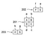
図2は本実施形態において光ピックアップに含まれる受光部およびトラッキングエラー信号演算回路の構成を示すブロック図である。図3は前記受光部に備えられるメインフォトディテクタおよびサブフォトディテクタの各受光領域を示す図である。図3において、メインフォトディテクタ201は図から見て縦横の4つに分割された受光素子の受光領域a,b,c,dを有し、先行サブフォトディテクタ202は図から見て横に2つに分割された受光素子の受光領域e,fを有し、後方サブフォトディテクタ203は図か見て横に2つに分割された受光素子の受光領域g,hを有する。ここでメインフォトディテクタ201の受光領域a,b,c,dの出力信号をA,B,C,Dとし、先行サブフォトディテクタ202の受光素子の受光領域e,fの出力信号をE,Fとし、後方サブフォトディテクタ203の受光領域g,hの出力信号をG,Hとする。
FIG. 2 is a block diagram showing a configuration of a light receiving unit and a tracking error signal calculation circuit included in the optical pickup in the present embodiment. FIG. 3 is a view showing each light receiving region of the main photo detector and the sub photo detector provided in the light receiving unit. In FIG. 3, a
図2において、光ピックアップ2は、光ディスクに対してメインビームとサブビームとから成るレーザ光を出射し、光ディスクの目的トラックからのメインビームの反射光を受光するメイン受光部2aと、前記目的トラックからずれた位置からのサブビームの反射光を受光するサブビーム受光部2bと、トラッキングエラー信号演算回路60とを含み構成されている。メイン受光部2aは、光ディスク上の目的トラックからのメインビームの反射光を受光するメインフォトディテクタ201(図3参照)を有し、メインフォトディテクタ201は信号A,B,C,Dを出力する。
In FIG. 2, an
また、サブ受光部2bは、光ディスク上の目的トラックからずれた位置からのサブビームの先行の反射光を受光する先行サブフォトディテクタ202(図3参照)と、光ディスク上の目的トラックからずれた位置からのサブビームの後方の反射光を受光する後方サブフォトディテクタ203(図3参照)とを有し、先行サブフォトディテクタ202は信号E,Fを出力し、後方サブフォトディテクタ203は信号G,Hを出力する。
Further, the sub
トラッキングエラー信号演算回路60は、和演算器61、和演算器62、差分演算器63、和演算器64、和演算器65、および差分演算器66を備えている。和演算器61は、メイン受光部2aからの信号Aと信号Dとの和を取り、信号(A+D)として出力する。和演算器62は、メイン受光部2aからの信号Bと信号Cとの和を取り、信号(B+C)として出力する。差分演算器63は、和演算器61からの信号(A+D)と和演算器62からの信号(B+C)との差を取り、信号[(A+D)−(B+C)]として出力する。この信号[(A+D)−(B+C)]は、TE(トラッキングエラー)信号となる。
The tracking error
和演算器64は、サブ受光部2bからの信号Eと信号Hとの和を取り、信号(E+H)として出力する。和演算器65は、サブ受光部2bからの信号Fと信号Gとの和を取り、信号(F+G)として出力する。差分演算器66は、和演算器64からの信号(E+H)と和演算器65からの信号(F+G)との差を取り、信号[(E+H)−(F+G)]として出力する。この信号[(E+H)−(F+G)]は、サブTE(トラッキングエラー)信号となる。
The
図4は本実施形態においてディスク判別の処理を説明するためのフローチャートである。このフローチャートおよび図1〜図3を参照してディスク判別の処理について説明する。 FIG. 4 is a flowchart for explaining the disk discrimination processing in this embodiment. The disc discrimination process will be described with reference to this flowchart and FIGS.
先ず、光ディスク1が光ディスク記録再生装置に挿入されると、システムコントローラ22は、光ディスク1が挿入されたことを検出し(ステップS1)、光ディスク1を立ち上げてディスク情報を読み出す処理である所謂マウント処理を開始する(ステップS2)。そして、システムコントローラ22の光ピックアップ制御手段221は、光ディスク1の記録面に対して1層用レーザ光のフォーカスを合わせるため、サーボ制御部4を制御して光ピックアップ2の図示しないフォーカス用アクチュエータを駆動させ、これにより、対物レンズを光ディスク1の記録面に対して垂直方向に移動させ、1層用レーザ光をフォーカスオンの状態にする(ステップS3)。
First, when the
このフォーカスオン状態において、システムコントローラ22のオフセット判定手段222は、前記1層用レーザ光が光ディスク1の記録面に照射されて反射された反射光のうち光ピックアップ2のメイン受光部2aから漏れた漏れ光の一部を光ピックアップ2のサブ受光部2bで受光して得られた光ピックアップ2からのサブTE信号(差分演算器66の出力信号)を測定して(ステップS4)、そのオフセットが閾値以上であるか否かを判定する(ステップS5)。
In this focus-on state, the offset
サブTE信号のオフセットが閾値以上であるか否かの判定を行う理由は、次のような理由によるものである。光ピックアップ2からのレーザ光が、光ディスク1が1層の光ディスクであっても2層の光ディスクであっても、光ディスク1の記録面に照射されるが、レーザ光のフォーカスは1層の光ディスクの記録面に設定されるので、挿入されている光ディスク1が2層の光ディスクの場合は、レーザ光が1層目の記録面に照射され、この照射されたレーザ光の一部が2層目の記録面まで届き、この2層目の記録面による反射光と1層目の記録面による反射光(メイン受光部2aに入射される反射光以外の反射光)とが漏れ光となる。
The reason why it is determined whether or not the offset of the sub TE signal is equal to or greater than the threshold value is as follows. The laser beam from the
一方、挿入されている光ディスク1が1層の光ディスクの場合は、メイン受光部2aに入射される反射光以外の反射光が漏れ光となる。2層の光ディスクによる漏れ光と1層の光ディスクによる漏れ光とを比べると、2層の光ディスクによる漏れ光が1層の光ディスクによる漏れ光よりも多くなり、その結果、サブTE信号のオフセットは2層の光ディスクの方が大きくなる。したがって、サブTE信号のオフセットが閾値以上であるか否かの判定を行うことによって、光ディスク1が2層の光ディスクであるか1層の光ディスクであるかを判定することができる。
On the other hand, when the inserted
システムコントローラ22のディスク判定手段223は、前記オフセットが閾値以上であると判定された場合は(ステップS5)、挿入されている光ディスク1を2層の光ディスクであると判定し(ステップS6)、前記オフセットが閾値未満であると判定された場合は(ステップS5)、挿入されている光ディスク1を1層の光ディスクであると判定する(ステップS8)。挿入されている光ディスク1が2層の光ディスクであると判定された場合は、システムコントローラ22は、2層の光ディスクに対応した設定(2層の光ディスクの場合のスピンドルモータ5の回転数を1層の光ディスクの場合のスピンドルモータ5の回転数の1.1倍になるようにするモータ制御設定などの設定)を行い(ステップS7)、挿入されている光ディスク1が1層の光ディスクであると判定された場合は、システムコントローラ22は、1層の光ディスクに対応した設定(1層の光ディスクの場合のスピンドルモータ5に対するモータ制御設定などの設定)を行う(ステップS9)。
When it is determined that the offset is greater than or equal to the threshold (step S5), the
以上説明したように本実施形態によれば、1層用レーザ光が光ディスクの記録面に照射されて反射された反射光のうち光ピックアップのメイン受光部から漏れた漏れ光の一部を光ピックアップのサブ受光部で受光して得られた光ピックアップからのサブトラッキングエラー信号のオフセットが閾値以上であるか否かを判定することにより、挿入されている光ディスクが2層の光ディスクであるか1層の光ディスクであるかの判定を行うようにしたので、光ディスクのリードインゾーンのディスク情報もしくはアドレス情報の読み取り前に、即ちマウント処理が終了するまでに、挿入されている光ディスクが2層の光ディスクであるか1層の光ディスクであるかを簡単な処理で判別することができ、これにより、挿入されている光ディスクに応じた設定処理が早くでき、この結果、挿入されている光ディスクに対して記録または再生を早く開始させることができる。 As described above, according to the present embodiment, a part of the leaked light leaked from the main light receiving portion of the optical pickup out of the reflected light that is reflected when the recording surface of the optical disc is irradiated with the laser light for one layer is picked up by the optical pickup. Whether the inserted optical disk is a two-layer optical disk or not is determined by determining whether or not the offset of the sub-tracking error signal from the optical pickup obtained by receiving the light at the sub light-receiving unit is greater than or equal to the threshold value. Therefore, before reading the disc information or address information in the lead-in zone of the optical disc, that is, before the mounting process is completed, the inserted optical disc is a two-layer optical disc. Whether it is a single-layer optical disk or not can be determined with a simple process. Setting process can be faster, as a result, it is possible to start earlier recording or reproducing the optical disc being inserted.
1 光ディスク
2 光ピックアップ
2a メイン受光部
2b サブ受光部
22 システムコントローラ
221 光ピックアップ制御手段
222 オフセット判定手段
223 ディスク判定手段
DESCRIPTION OF
Claims (4)
光ディスクが挿入され、マウント処理が開始して、この光ディスクの記録面に対して1層用レーザ光のフォーカスを合わせるフォーカスオン状態で1層用レーザ光を出射させるように前記光ピックアップを制御する光ピックアップ制御手段と、
前記1層用レーザ光が前記フォーカスオン状態で光ディスクの記録面に照射されて反射された反射光のうち前記光ピックアップのメイン受光部から漏れた漏れ光の一部を前記光ピックアップのサブ受光部で受光して得られた前記光ピックアップからのサブトラッキングエラー信号を測定して、そのサブトラッキングエラー信号のオフセットが閾値以上であるか否かを判定するオフセット判定手段と、
前記オフセットが閾値以上であると判定された場合は挿入されている光ディスクを2層の光ディスクであると判定し、前記オフセットが閾値未満であると判定された場合は挿入されている光ディスクを1層の光ディスクであると判定するディスク判定手段と、を有するシステムコントローラを備えたことを特徴とする光ディスク記録再生装置。 In an optical disc recording / reproducing apparatus equipped with an optical pickup capable of emitting at least two types of laser beams having different wavelengths and capable of recording / reproducing information with respect to a single-layer optical disc or a double-layer optical disc,
Light for controlling the optical pickup so that the single layer laser beam is emitted in a focus-on state in which the optical disc is inserted and the mounting process is started, and the focus of the single layer laser beam is focused on the recording surface of the optical disc. Pickup control means;
A part of the leaked light leaked from the main light receiving portion of the optical pickup out of the reflected light that is reflected when the laser light for the first layer is irradiated onto the recording surface of the optical disc in the focus-on state is sub-light receiving portion of the optical pickup An offset determination means for measuring a sub-tracking error signal from the optical pickup obtained by receiving the light and determining whether or not the offset of the sub-tracking error signal is equal to or greater than a threshold;
If it is determined that the offset is greater than or equal to the threshold value, the inserted optical disk is determined to be a two-layer optical disk, and if the offset is determined to be less than the threshold value, one optical disk is inserted. An optical disc recording / reproducing apparatus comprising a system controller having disc determination means for determining that the disc is an optical disc.
光ディスクが挿入され、マウント処理が開始して、この光ディスクの記録面に対して1層用レーザ光のフォーカスを合わせるフォーカスオン状態で1層用レーザ光を前記光ピックアップから出射させ、前記1層用レーザ光が前記フォーカスオン状態で光ディスクの記録面に照射されて反射された反射光のうちの漏れ光を受光して得られた前記光ピックアップからのサブトラッキングエラー信号を測定し、そのサブトラッキングエラー信号のオフセットが、閾値以上であれば挿入されている光ディスクを2層の光ディスクであると判定し、閾値未満であれば挿入されている光ディスクを1層の光ディスクであるという判定を行うシステムコントローラを備えたことを特徴とする光ディスク記録再生装置。 In an optical disc recording / reproducing apparatus equipped with an optical pickup capable of emitting at least two types of laser beams having different wavelengths and capable of recording / reproducing information with respect to a single-layer optical disc or a double-layer optical disc,
The optical disk is inserted, the mounting process starts, and the single-layer laser light is emitted from the optical pickup in a focus-on state in which the focus of the single-layer laser light is focused on the recording surface of the optical disk. The sub-tracking error signal is measured by measuring the sub-tracking error signal from the optical pickup obtained by receiving the leakage light of the reflected light that is reflected when the laser light is irradiated onto the recording surface of the optical disk in the focus-on state. A system controller that determines that the inserted optical disk is a two-layer optical disk if the signal offset is equal to or greater than a threshold value, and determines that the inserted optical disk is a single-layer optical disk if the signal offset is less than the threshold value; An optical disc recording / reproducing apparatus comprising:
Priority Applications (1)
| Application Number | Priority Date | Filing Date | Title |
|---|---|---|---|
| JP2005338655A JP2007149162A (en) | 2005-11-24 | 2005-11-24 | Optical disk recording/reproducing device |
Applications Claiming Priority (1)
| Application Number | Priority Date | Filing Date | Title |
|---|---|---|---|
| JP2005338655A JP2007149162A (en) | 2005-11-24 | 2005-11-24 | Optical disk recording/reproducing device |
Publications (1)
| Publication Number | Publication Date |
|---|---|
| JP2007149162A true JP2007149162A (en) | 2007-06-14 |
Family
ID=38210421
Family Applications (1)
| Application Number | Title | Priority Date | Filing Date |
|---|---|---|---|
| JP2005338655A Pending JP2007149162A (en) | 2005-11-24 | 2005-11-24 | Optical disk recording/reproducing device |
Country Status (1)
| Country | Link |
|---|---|
| JP (1) | JP2007149162A (en) |
-
2005
- 2005-11-24 JP JP2005338655A patent/JP2007149162A/en active Pending
Similar Documents
| Publication | Publication Date | Title |
|---|---|---|
| KR100611091B1 (en) | Optical disk apparatus and method for controlling the same | |
| JP4713839B2 (en) | Optical disc apparatus and focus jump control method thereof | |
| US5974014A (en) | Disc reproducing apparatus and method | |
| JP4483859B2 (en) | Information recording / reproducing device | |
| JP2007149162A (en) | Optical disk recording/reproducing device | |
| KR100580769B1 (en) | Multi-layered optical disc recording / playback apparatus and method | |
| JP4236647B2 (en) | Optical disk device | |
| JP3556394B2 (en) | Digital disk player and disk identification method thereof | |
| US20060171265A1 (en) | Optical disk apparatus | |
| JPH11296962A (en) | Optical disc identification device | |
| JP2008287781A (en) | Optical disk device | |
| JP4840272B2 (en) | Optical disk device | |
| KR100782182B1 (en) | Multi-layer optical disc recording / playback apparatus and method | |
| JP3862176B2 (en) | Optical disk playback device | |
| JP4504227B2 (en) | Optical disc, optical disc apparatus, and optical disc processing method | |
| JP4252011B2 (en) | Information recording / reproducing apparatus, information recording / reproducing method, program, and storage medium | |
| JP4415031B2 (en) | Disc discriminating method and disc reproducing apparatus | |
| US20060092786A1 (en) | Optical disk recording and reproducing device | |
| JP2008276821A (en) | Warp detecting method of optical disk, recording method of optical disk, and optical disk recording and playback device | |
| JP2005122822A (en) | Optical disk recording and reproducing device | |
| JP2007310965A (en) | Optical disk recording and playback device | |
| JP2007226869A (en) | Optical disk device | |
| JP2007004950A (en) | Optical disk apparatus and hybrid optical disk | |
| JP2006196093A (en) | Optical disk device | |
| JP2004213880A (en) | Optical pickup device and information reproducing device |