JP2007149603A - 漏電遮断器 - Google Patents
漏電遮断器 Download PDFInfo
- Publication number
- JP2007149603A JP2007149603A JP2005345857A JP2005345857A JP2007149603A JP 2007149603 A JP2007149603 A JP 2007149603A JP 2005345857 A JP2005345857 A JP 2005345857A JP 2005345857 A JP2005345857 A JP 2005345857A JP 2007149603 A JP2007149603 A JP 2007149603A
- Authority
- JP
- Japan
- Prior art keywords
- circuit
- phase
- earth leakage
- leakage
- zero
- Prior art date
- Legal status (The legal status is an assumption and is not a legal conclusion. Google has not performed a legal analysis and makes no representation as to the accuracy of the status listed.)
- Granted
Links
Images




Classifications
-
- H—ELECTRICITY
- H02—GENERATION; CONVERSION OR DISTRIBUTION OF ELECTRIC POWER
- H02H—EMERGENCY PROTECTIVE CIRCUIT ARRANGEMENTS
- H02H1/00—Details of emergency protective circuit arrangements
- H02H1/06—Arrangements for supplying operative power
-
- H—ELECTRICITY
- H02—GENERATION; CONVERSION OR DISTRIBUTION OF ELECTRIC POWER
- H02H—EMERGENCY PROTECTIVE CIRCUIT ARRANGEMENTS
- H02H3/00—Emergency protective circuit arrangements for automatic disconnection directly responsive to an undesired change from normal electric working condition with or without subsequent reconnection ; integrated protection
- H02H3/02—Details
- H02H3/04—Details with warning or supervision in addition to disconnection, e.g. for indicating that protective apparatus has functioned
- H02H3/044—Checking correct functioning of protective arrangements, e.g. by simulating a fault
-
- H—ELECTRICITY
- H02—GENERATION; CONVERSION OR DISTRIBUTION OF ELECTRIC POWER
- H02H—EMERGENCY PROTECTIVE CIRCUIT ARRANGEMENTS
- H02H3/00—Emergency protective circuit arrangements for automatic disconnection directly responsive to an undesired change from normal electric working condition with or without subsequent reconnection ; integrated protection
- H02H3/16—Emergency protective circuit arrangements for automatic disconnection directly responsive to an undesired change from normal electric working condition with or without subsequent reconnection ; integrated protection responsive to fault current to earth, frame or mass
- H02H3/162—Emergency protective circuit arrangements for automatic disconnection directly responsive to an undesired change from normal electric working condition with or without subsequent reconnection ; integrated protection responsive to fault current to earth, frame or mass for AC systems
- H02H3/165—Emergency protective circuit arrangements for automatic disconnection directly responsive to an undesired change from normal electric working condition with or without subsequent reconnection ; integrated protection responsive to fault current to earth, frame or mass for AC systems for three-phase systems
-
- H—ELECTRICITY
- H02—GENERATION; CONVERSION OR DISTRIBUTION OF ELECTRIC POWER
- H02H—EMERGENCY PROTECTIVE CIRCUIT ARRANGEMENTS
- H02H3/00—Emergency protective circuit arrangements for automatic disconnection directly responsive to an undesired change from normal electric working condition with or without subsequent reconnection ; integrated protection
- H02H3/26—Emergency protective circuit arrangements for automatic disconnection directly responsive to an undesired change from normal electric working condition with or without subsequent reconnection ; integrated protection responsive to difference between voltages or between currents; responsive to phase angle between voltages or between currents
- H02H3/32—Emergency protective circuit arrangements for automatic disconnection directly responsive to an undesired change from normal electric working condition with or without subsequent reconnection ; integrated protection responsive to difference between voltages or between currents; responsive to phase angle between voltages or between currents involving comparison of the voltage or current values at corresponding points in different conductors of a single system, e.g. of currents in go and return conductors
- H02H3/34—Emergency protective circuit arrangements for automatic disconnection directly responsive to an undesired change from normal electric working condition with or without subsequent reconnection ; integrated protection responsive to difference between voltages or between currents; responsive to phase angle between voltages or between currents involving comparison of the voltage or current values at corresponding points in different conductors of a single system, e.g. of currents in go and return conductors of a three-phase system
- H02H3/347—Emergency protective circuit arrangements for automatic disconnection directly responsive to an undesired change from normal electric working condition with or without subsequent reconnection ; integrated protection responsive to difference between voltages or between currents; responsive to phase angle between voltages or between currents involving comparison of the voltage or current values at corresponding points in different conductors of a single system, e.g. of currents in go and return conductors of a three-phase system using summation current transformers
-
- G—PHYSICS
- G01—MEASURING; TESTING
- G01R—MEASURING ELECTRIC VARIABLES; MEASURING MAGNETIC VARIABLES
- G01R31/00—Arrangements for testing electric properties; Arrangements for locating electric faults; Arrangements for electrical testing characterised by what is being tested not provided for elsewhere
- G01R31/50—Testing of electric apparatus, lines, cables or components for short-circuits, continuity, leakage current or incorrect line connections
- G01R31/52—Testing for short-circuits, leakage current or ground faults
-
- H—ELECTRICITY
- H02—GENERATION; CONVERSION OR DISTRIBUTION OF ELECTRIC POWER
- H02H—EMERGENCY PROTECTIVE CIRCUIT ARRANGEMENTS
- H02H3/00—Emergency protective circuit arrangements for automatic disconnection directly responsive to an undesired change from normal electric working condition with or without subsequent reconnection ; integrated protection
- H02H3/26—Emergency protective circuit arrangements for automatic disconnection directly responsive to an undesired change from normal electric working condition with or without subsequent reconnection ; integrated protection responsive to difference between voltages or between currents; responsive to phase angle between voltages or between currents
- H02H3/32—Emergency protective circuit arrangements for automatic disconnection directly responsive to an undesired change from normal electric working condition with or without subsequent reconnection ; integrated protection responsive to difference between voltages or between currents; responsive to phase angle between voltages or between currents involving comparison of the voltage or current values at corresponding points in different conductors of a single system, e.g. of currents in go and return conductors
- H02H3/33—Emergency protective circuit arrangements for automatic disconnection directly responsive to an undesired change from normal electric working condition with or without subsequent reconnection ; integrated protection responsive to difference between voltages or between currents; responsive to phase angle between voltages or between currents involving comparison of the voltage or current values at corresponding points in different conductors of a single system, e.g. of currents in go and return conductors using summation current transformers
- H02H3/334—Emergency protective circuit arrangements for automatic disconnection directly responsive to an undesired change from normal electric working condition with or without subsequent reconnection ; integrated protection responsive to difference between voltages or between currents; responsive to phase angle between voltages or between currents involving comparison of the voltage or current values at corresponding points in different conductors of a single system, e.g. of currents in go and return conductors using summation current transformers with means to produce an artificial imbalance for other protection or monitoring reasons or remote control
- H02H3/335—Emergency protective circuit arrangements for automatic disconnection directly responsive to an undesired change from normal electric working condition with or without subsequent reconnection ; integrated protection responsive to difference between voltages or between currents; responsive to phase angle between voltages or between currents involving comparison of the voltage or current values at corresponding points in different conductors of a single system, e.g. of currents in go and return conductors using summation current transformers with means to produce an artificial imbalance for other protection or monitoring reasons or remote control the main function being self testing of the device
Landscapes
- Engineering & Computer Science (AREA)
- Power Engineering (AREA)
- Emergency Protection Circuit Devices (AREA)
- Breakers (AREA)
Abstract
【解決手段】三相電路の3本の電力線が挿通され、三相電路の漏洩電流を検出する零相変流器5と、この零相変流器5で検出された信号のレベル判定を行う漏電検出回路7と、この漏電検出回路7の出力に応動して電路接点4を開離させる電磁石装置8と、漏電テスト時に作動され、零相変流器5にテスト用の電流を流す漏電テスト回路12とを備えた漏電遮断器において、漏電検出回路7および電磁石装置8は、三相電路の3本の電力線より整流回路10を介して、動作電力の供給を受け、かつ、漏電テスト回路12は整流回路10の出力端に接続されている。
【選択図】図1
Description
然るに、これら漏電検出回路、および電磁石装置には、動作電力が必要となるが、この動作電力は、漏電遮断器の内部(例えば、電路電圧AC400V)から採り、所定の電圧(例えば、DC12V)に降下させ、供給されている。
このとき、3極用漏電遮断器では、3極(便宜上、R相、S相、T相とする。すなわち、S相が中極に相当する。)のうち、外側2極、すなわち、R−T相間から採るのが一般的であり、このことが、3極用漏電遮断器を単相電路に使用する場合の制約条件である、R−T相間への接続となっている。
旧来のJIS C8371(すなわち、日本独自の規格)との違いの一つに、三相電路のある一相が欠相しても、漏電機能は正常に動作せねばならないことが決められている。
したがって、前述したように、R−T相間から電圧を採っている場合、S相の欠相では問題ないが、R相、もしくはT相が欠相したときは、直ちに漏電機能を喪失してしまう。
この方式によれば、ある一相が欠相したとしても、残る二相で動作電力を生成することができるので、漏電機能は正常に動作し続ける。
また、単相電路に使用する場合、必ずしもS相を空ける必要がない、つまり、R−S相間、あるいはS−T相間に接続することが可能という、波及効果もある(例えば、特許文献1参照)。
この漏電テスト回路は、特許文献1の図1からも明らかなように、零相変流器に挿通(あるいは巻回)されたリード線が、テストスイッチ(TS)、および抵抗素子を介して、R−T相間に接続されることで構成され、TSの押動により、零相変流器に擬似漏洩電流が流れることで、漏電機能の良否を見極めることができる。
ここで、漏電テスト回路は、前述したように、R−T相間に接続されているので、R相、もしくはT相が欠相した場合は、このテストが機能しないことになる。
この欠相時における漏電テスト機能は、いずれの規格においても規定化されていないものの、例えば、製品にこの旨の注意書きを記するなどの煩わしさは否めない。
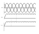
図1はこの発明の実施の形態1における3極用漏電遮断器の内部接続図、図2および3は、各ポイントの波形を示したものであり、図2は三相電路に、図3は単相電路に、それぞれ接続した場合である。
なお、図2および3における添字(a)(b)(c)は、それぞれ、(a)が電路波形、(b)が擬似漏洩電流波形、(c)が零相変流器の出力波形を示している。
なお、この電力線3は、便宜上、図中、左側から右側にむけてR、S、Tの符号を付すこととする。電力線3は、電路接点4の負荷側(紙面上、下側)に配設された零相変流器5に挿通されており、この零相変流器5からは、電力線3を流れる電流のバランスが崩れたとき、すなわち、電路から大地に対し漏洩電流が発生した場合、そのレベルに比例した信号が出力される。
なお、感度切換装置6は、保護する目的に応じて、その感度レベル(例:100mAか500mA)を変更したいときや、漏電遮断器101同士の協調を得たいときに活用される。また、漏電検出回路7は集積回路で構成されることが一般的である。
したがって、特許文献1と同様、どの相で欠相が起こったとしても、電源回路からは所定の値が出力されるので、漏電機能に支障をきたすことがない。なお、感度切換装置6、漏電検出回路7、全波整流回路10、および電源回路11は1枚、もしくは複数の基板上に実装されている。
この漏電テスト回路12は、特許文献1と同様、抵抗素子13、零相変流器5に挿通、あるいは巻回された漏電テストリード線14、および漏電テストスイッチ15より構成されており、漏電テストスイッチ15と連動する図示しない漏電テストボタンを押動することで、零相変流器5に擬似漏洩電流が流れ、電磁石装置8の励磁に至るのは、前述した実際の漏洩電流発生時の一連の動作と同様である。
なお、零相変流器5への挿通、あるいは巻回への選択は、漏電遮断器101の感度レベルに適した擬似漏洩電流を得るにあたり、適宜決めればよい。
すなわち、図2(c)および図3(c)から明らかなように、零相変流器5には絶えずレベル変化する信号が出力されているので、仮に一相が欠相したとしても、その相に該当する信号は得られないものの、依然、レベル変化する信号は出力され続けるので、電磁石装置8の励磁を行うことが可能となる。
それにも増して、単相電路に接続する場合、どの相間に接続しても、漏電テストを行うことができるので、使い勝手のよい3極用漏電遮断器を提供することができる。
しかも、漏電テスト回路12の構成は、接続箇所以外は変更させていないので、コストアップを招くこともない。また、抵抗素子13には、交流に代え全波整流を通電させることから、この抵抗素子13の負担が減り、耐熱容量の小さい小形で安価な抵抗素子の使用が期待できる。
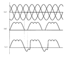
図4〜6はこの発明の実施の形態2における、図1〜3相当図である。
すなわち、実施の形態1と同様、図5(c)および図6(c)からも明らかなように、零相変流器5には絶えずレベル変化する信号が出力されているので、仮に一相が欠相したとしても、その相に該当する信号は得られないものの、依然、レベル変化する信号は出力され続けるので、電磁石装置8の励磁を行うことが可能となる。
この出力を利用して、JIS C8201−2−2で規定されているA型漏電遮断器(実施の形態1で実現可能)に加え、AC型漏電遮断器(つまり、旧来のJIS C8371の規定に相当)も製作することが可能となる。
このように、実施の形態1の効果に加え、製品のバリエーションが広がるとともに、さらに耐熱容量の小さい抵抗素子が使用できる、という波及効果が期待できる。
6 感度切換装置、7 漏電検出回路、8 電磁石装置、9 漏電表示ボタン、
10 全波整流回路、11 電源回路、12 漏電テスト回路、13 抵抗素子、
14 漏電テストリード線、15 漏電テストスイッチ、20 半波整流回路、
101 3極用漏電遮断器。
Claims (5)
- 三相電路の3本の電力線が挿通され、上記三相電路の漏洩電流を検出する零相変流器と、この零相変流器で検出された信号のレベル判定を行う漏電検出回路と、この漏電検出回路の出力に応動して電路接点を開離させる電磁石装置と、漏電テスト時に作動され、上記零相変流器にテスト用の電流を流す漏電テスト回路とを備えた漏電遮断器において、
上記漏電検出回路および電磁石装置は、上記三相電路の3本の電力線より整流回路を介して、動作電力の供給を受け、かつ、上記漏電テスト回路は上記整流回路の出力端に接続されていることを特徴とする漏電遮断器。 - 上記整流回路が全波整流回路であることを特徴とする請求項1に記載の漏電遮断器。
- 上記整流回路が半波整流回路であることを特徴とする請求項1に記載の漏電遮断器。
- 上記漏電テスト回路を作動させたとき、上記零相変流器の出力が正負両方あらわれることを特徴とする請求項3に記載の漏電遮断器。
- 上記漏電テスト回路は、上記整流回路の出力端に直列に接続された抵抗素子、漏電テストスイッチ、および上記零相変流器に挿通あるいは巻回される漏電テストリード線で構成されたことを特徴とする請求項1乃至4のいずれか一つに記載の漏電遮断器。
Priority Applications (3)
| Application Number | Priority Date | Filing Date | Title |
|---|---|---|---|
| JP2005345857A JP4369417B2 (ja) | 2005-11-30 | 2005-11-30 | 漏電遮断器 |
| EP06010637.4A EP1793466A3 (en) | 2005-11-30 | 2006-05-24 | Circuit-breakers incorporating residual current protection |
| CNB2006101099823A CN100492796C (zh) | 2005-11-30 | 2006-08-25 | 漏电断路器 |
Applications Claiming Priority (1)
| Application Number | Priority Date | Filing Date | Title |
|---|---|---|---|
| JP2005345857A JP4369417B2 (ja) | 2005-11-30 | 2005-11-30 | 漏電遮断器 |
Publications (2)
| Publication Number | Publication Date |
|---|---|
| JP2007149603A true JP2007149603A (ja) | 2007-06-14 |
| JP4369417B2 JP4369417B2 (ja) | 2009-11-18 |
Family
ID=37786906
Family Applications (1)
| Application Number | Title | Priority Date | Filing Date |
|---|---|---|---|
| JP2005345857A Expired - Fee Related JP4369417B2 (ja) | 2005-11-30 | 2005-11-30 | 漏電遮断器 |
Country Status (3)
| Country | Link |
|---|---|
| EP (1) | EP1793466A3 (ja) |
| JP (1) | JP4369417B2 (ja) |
| CN (1) | CN100492796C (ja) |
Cited By (5)
| Publication number | Priority date | Publication date | Assignee | Title |
|---|---|---|---|---|
| JP2009089574A (ja) * | 2007-10-03 | 2009-04-23 | Mitsubishi Electric Corp | 漏電遮断器 |
| JP2009095125A (ja) * | 2007-10-09 | 2009-04-30 | Mitsubishi Electric Corp | 電源回路及びこの電源回路を用いた漏電遮断器 |
| JP2009104806A (ja) * | 2007-10-19 | 2009-05-14 | Kawamura Electric Inc | 3相漏電遮断器 |
| JP2016024963A (ja) * | 2014-07-22 | 2016-02-08 | 株式会社日立産機システム | 漏電遮断器 |
| JP2022012470A (ja) * | 2020-07-01 | 2022-01-17 | 河村電器産業株式会社 | 漏電遮断器 |
Families Citing this family (6)
| Publication number | Priority date | Publication date | Assignee | Title |
|---|---|---|---|---|
| CN101888082B (zh) * | 2010-07-09 | 2013-05-01 | 上海诺雅克电气有限公司 | 剩余电流保护器 |
| CN109196746B (zh) * | 2016-05-17 | 2020-07-07 | 三菱电机株式会社 | 漏电断路器 |
| CN107332201A (zh) * | 2017-08-23 | 2017-11-07 | 浙江夏兴电子科技股份有限公司 | 一种适用于三相电路模拟泄漏电流产生电路 |
| CN111465863A (zh) * | 2017-12-12 | 2020-07-28 | Ad电力株式会社 | 三相四线式带电绝缘电阻测量用零相变流装置及带电绝缘电阻测量装置 |
| CN112763900B (zh) * | 2020-12-25 | 2021-11-19 | 西安交通大学 | 一种混合式直流断路器耗能支路mov状态测量电路及方法 |
| CN115343562B (zh) * | 2022-09-02 | 2025-09-19 | 常熟开关制造有限公司(原常熟开关厂) | 剩余电流保护试验方法、装置及断路器 |
Citations (6)
| Publication number | Priority date | Publication date | Assignee | Title |
|---|---|---|---|---|
| JPS61128719A (ja) * | 1984-11-22 | 1986-06-16 | 株式会社日立製作所 | 回路遮断器 |
| JP2004266894A (ja) * | 2003-02-28 | 2004-09-24 | Kawamura Electric Inc | 3相4線式欠相保護付き回路遮断器 |
| JP2005158559A (ja) * | 2003-11-27 | 2005-06-16 | Fuji Electric Fa Components & Systems Co Ltd | 漏電遮断器 |
| JP2005251410A (ja) * | 2004-03-01 | 2005-09-15 | Fuji Electric Fa Components & Systems Co Ltd | 漏電遮断器 |
| JP2005340082A (ja) * | 2004-05-28 | 2005-12-08 | Mitsubishi Electric Corp | 漏電遮断器 |
| JP2006302601A (ja) * | 2005-04-19 | 2006-11-02 | Fuji Electric Holdings Co Ltd | 漏電遮断器 |
Family Cites Families (6)
| Publication number | Priority date | Publication date | Assignee | Title |
|---|---|---|---|---|
| DE2653453C3 (de) * | 1976-11-25 | 1986-10-02 | Felten & Guilleaume Energietechnik GmbH, 5000 Köln | Schaltungsanordnung für eine aus der Netzspannung über Gleichrichterelemente abgeleitete Hilfsspannung für mehrpolige Fehlerstrom-Schutzschalter |
| DE2938124A1 (de) * | 1979-09-20 | 1981-04-09 | Siemens AG, 1000 Berlin und 8000 München | Schaltungsanordnung, insbesondere fuer mehrpolige fehlerstromschutzschalter |
| US4851950A (en) * | 1987-06-09 | 1989-07-25 | Bassani Ticino, S.P.A. | Electrical apparatus for magnetothermal and differential protection |
| GB2286936B (en) * | 1994-02-25 | 1997-09-03 | Shakira Ltd | Residual current circuit |
| KR20020041973A (ko) * | 2000-11-29 | 2002-06-05 | 구자홍 | 누전 차단기 |
| JP2004015961A (ja) * | 2002-06-10 | 2004-01-15 | Kawamura Electric Inc | 三相欠相保護付漏電遮断器 |
-
2005
- 2005-11-30 JP JP2005345857A patent/JP4369417B2/ja not_active Expired - Fee Related
-
2006
- 2006-05-24 EP EP06010637.4A patent/EP1793466A3/en not_active Withdrawn
- 2006-08-25 CN CNB2006101099823A patent/CN100492796C/zh not_active Expired - Fee Related
Patent Citations (6)
| Publication number | Priority date | Publication date | Assignee | Title |
|---|---|---|---|---|
| JPS61128719A (ja) * | 1984-11-22 | 1986-06-16 | 株式会社日立製作所 | 回路遮断器 |
| JP2004266894A (ja) * | 2003-02-28 | 2004-09-24 | Kawamura Electric Inc | 3相4線式欠相保護付き回路遮断器 |
| JP2005158559A (ja) * | 2003-11-27 | 2005-06-16 | Fuji Electric Fa Components & Systems Co Ltd | 漏電遮断器 |
| JP2005251410A (ja) * | 2004-03-01 | 2005-09-15 | Fuji Electric Fa Components & Systems Co Ltd | 漏電遮断器 |
| JP2005340082A (ja) * | 2004-05-28 | 2005-12-08 | Mitsubishi Electric Corp | 漏電遮断器 |
| JP2006302601A (ja) * | 2005-04-19 | 2006-11-02 | Fuji Electric Holdings Co Ltd | 漏電遮断器 |
Cited By (6)
| Publication number | Priority date | Publication date | Assignee | Title |
|---|---|---|---|---|
| JP2009089574A (ja) * | 2007-10-03 | 2009-04-23 | Mitsubishi Electric Corp | 漏電遮断器 |
| JP2009095125A (ja) * | 2007-10-09 | 2009-04-30 | Mitsubishi Electric Corp | 電源回路及びこの電源回路を用いた漏電遮断器 |
| JP2009104806A (ja) * | 2007-10-19 | 2009-05-14 | Kawamura Electric Inc | 3相漏電遮断器 |
| JP2016024963A (ja) * | 2014-07-22 | 2016-02-08 | 株式会社日立産機システム | 漏電遮断器 |
| JP2022012470A (ja) * | 2020-07-01 | 2022-01-17 | 河村電器産業株式会社 | 漏電遮断器 |
| JP7511404B2 (ja) | 2020-07-01 | 2024-07-05 | 河村電器産業株式会社 | 漏電遮断器 |
Also Published As
| Publication number | Publication date |
|---|---|
| CN1976158A (zh) | 2007-06-06 |
| EP1793466A2 (en) | 2007-06-06 |
| EP1793466A3 (en) | 2016-08-24 |
| JP4369417B2 (ja) | 2009-11-18 |
| CN100492796C (zh) | 2009-05-27 |
Similar Documents
| Publication | Publication Date | Title |
|---|---|---|
| US10840698B2 (en) | Leakage current detection and protection device for power cord | |
| US8570181B2 (en) | Method and apparatus for supervisory circuit for ground fault circuit interrupt device | |
| US8472155B2 (en) | Leakage detection protective circuit | |
| US7215520B2 (en) | Circuit interrupter including arc fault test and/or ground fault test failure indicator | |
| CN101965620B (zh) | 漏电断路器 | |
| US6671150B2 (en) | Circuit breaker for detecting an excessive voltage and tripping responsive thereto | |
| JP4931754B2 (ja) | 漏電遮断器 | |
| JP4369417B2 (ja) | 漏電遮断器 | |
| JP4935455B2 (ja) | 漏電検出装置 | |
| JP2005158559A (ja) | 漏電遮断器 | |
| JP4400255B2 (ja) | 漏電遮断器 | |
| CN103295852B (zh) | 漏电断路器 | |
| KR101508922B1 (ko) | 센서 분리형 전원 상태 자동 기록 시스템 | |
| JP2006302601A (ja) | 漏電遮断器 | |
| JP6221844B2 (ja) | 漏電遮断器 | |
| JP4839772B2 (ja) | 耐電圧テスト用スイッチおよび漏電遮断器 | |
| US6714396B2 (en) | Undervoltage tripping device | |
| JP2004015961A (ja) | 三相欠相保護付漏電遮断器 | |
| JP4395009B2 (ja) | 漏電遮断器 | |
| JP3960074B2 (ja) | 漏電検出装置のテスト回路 | |
| JP2843172B2 (ja) | 負荷制御装置 | |
| JP2010040326A (ja) | 漏電遮断器 | |
| KR20120090872A (ko) | 대기전력 자동차단형 꽂음접속식 누전차단기 | |
| JPH10208615A (ja) | 分離形漏電保護リレー | |
| JPH10302603A (ja) | 回路遮断器 |
Legal Events
| Date | Code | Title | Description |
|---|---|---|---|
| A621 | Written request for application examination |
Free format text: JAPANESE INTERMEDIATE CODE: A621 Effective date: 20080402 |
|
| A977 | Report on retrieval |
Free format text: JAPANESE INTERMEDIATE CODE: A971007 Effective date: 20090529 |
|
| A131 | Notification of reasons for refusal |
Free format text: JAPANESE INTERMEDIATE CODE: A131 Effective date: 20090609 |
|
| A521 | Request for written amendment filed |
Free format text: JAPANESE INTERMEDIATE CODE: A523 Effective date: 20090716 |
|
| TRDD | Decision of grant or rejection written | ||
| A01 | Written decision to grant a patent or to grant a registration (utility model) |
Free format text: JAPANESE INTERMEDIATE CODE: A01 Effective date: 20090818 |
|
| A01 | Written decision to grant a patent or to grant a registration (utility model) |
Free format text: JAPANESE INTERMEDIATE CODE: A01 |
|
| A61 | First payment of annual fees (during grant procedure) |
Free format text: JAPANESE INTERMEDIATE CODE: A61 Effective date: 20090827 |
|
| R151 | Written notification of patent or utility model registration |
Ref document number: 4369417 Country of ref document: JP Free format text: JAPANESE INTERMEDIATE CODE: R151 |
|
| FPAY | Renewal fee payment (event date is renewal date of database) |
Free format text: PAYMENT UNTIL: 20120904 Year of fee payment: 3 |
|
| FPAY | Renewal fee payment (event date is renewal date of database) |
Free format text: PAYMENT UNTIL: 20130904 Year of fee payment: 4 |
|
| R250 | Receipt of annual fees |
Free format text: JAPANESE INTERMEDIATE CODE: R250 |
|
| R250 | Receipt of annual fees |
Free format text: JAPANESE INTERMEDIATE CODE: R250 |
|
| R250 | Receipt of annual fees |
Free format text: JAPANESE INTERMEDIATE CODE: R250 |
|
| R250 | Receipt of annual fees |
Free format text: JAPANESE INTERMEDIATE CODE: R250 |
|
| R250 | Receipt of annual fees |
Free format text: JAPANESE INTERMEDIATE CODE: R250 |
|
| R250 | Receipt of annual fees |
Free format text: JAPANESE INTERMEDIATE CODE: R250 |
|
| R250 | Receipt of annual fees |
Free format text: JAPANESE INTERMEDIATE CODE: R250 |
|
| R250 | Receipt of annual fees |
Free format text: JAPANESE INTERMEDIATE CODE: R250 |
|
| R250 | Receipt of annual fees |
Free format text: JAPANESE INTERMEDIATE CODE: R250 |
|
| LAPS | Cancellation because of no payment of annual fees |