JP2007155100A - Outside joint member for constant velocity universal joint - Google Patents
Outside joint member for constant velocity universal joint Download PDFInfo
- Publication number
- JP2007155100A JP2007155100A JP2005355046A JP2005355046A JP2007155100A JP 2007155100 A JP2007155100 A JP 2007155100A JP 2005355046 A JP2005355046 A JP 2005355046A JP 2005355046 A JP2005355046 A JP 2005355046A JP 2007155100 A JP2007155100 A JP 2007155100A
- Authority
- JP
- Japan
- Prior art keywords
- joint member
- constant velocity
- velocity universal
- carburizing
- hardened layer
- Prior art date
- Legal status (The legal status is an assumption and is not a legal conclusion. Google has not performed a legal analysis and makes no representation as to the accuracy of the status listed.)
- Withdrawn
Links
- 238000005255 carburizing Methods 0.000 claims abstract description 35
- 238000010791 quenching Methods 0.000 claims abstract description 21
- 230000000171 quenching effect Effects 0.000 claims abstract description 21
- 230000005540 biological transmission Effects 0.000 claims description 10
- 238000006073 displacement reaction Methods 0.000 claims description 3
- 230000002265 prevention Effects 0.000 claims description 3
- 238000003763 carbonization Methods 0.000 claims description 2
- 230000003068 static effect Effects 0.000 abstract description 8
- 239000010410 layer Substances 0.000 description 40
- 238000000034 method Methods 0.000 description 9
- OKTJSMMVPCPJKN-UHFFFAOYSA-N Carbon Chemical compound [C] OKTJSMMVPCPJKN-UHFFFAOYSA-N 0.000 description 6
- 229910000831 Steel Inorganic materials 0.000 description 6
- 229910052799 carbon Inorganic materials 0.000 description 6
- 239000010959 steel Substances 0.000 description 6
- 238000004519 manufacturing process Methods 0.000 description 5
- 229910001209 Low-carbon steel Inorganic materials 0.000 description 4
- 230000002093 peripheral effect Effects 0.000 description 4
- 239000002344 surface layer Substances 0.000 description 3
- 229910001339 C alloy Inorganic materials 0.000 description 2
- 230000006698 induction Effects 0.000 description 2
- 239000007788 liquid Substances 0.000 description 2
- 230000003647 oxidation Effects 0.000 description 2
- 238000007254 oxidation reaction Methods 0.000 description 2
- 239000007787 solid Substances 0.000 description 2
- 230000000694 effects Effects 0.000 description 1
- 238000009661 fatigue test Methods 0.000 description 1
- 238000010438 heat treatment Methods 0.000 description 1
- 239000000463 material Substances 0.000 description 1
- 239000002184 metal Substances 0.000 description 1
- 238000012986 modification Methods 0.000 description 1
- 230000004048 modification Effects 0.000 description 1
- 238000007747 plating Methods 0.000 description 1
- 238000005096 rolling process Methods 0.000 description 1
Images


Landscapes
- Solid-Phase Diffusion Into Metallic Material Surfaces (AREA)
- Heat Treatment Of Articles (AREA)
Abstract
Description
本発明は、等速自在継手の外側継手部材に関するものである。 The present invention relates to an outer joint member of a constant velocity universal joint.
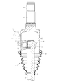
図5に示すように、等速自在継手(トリポート型等速自在継手)1は、外側継手部材2と、内側継手部材としてのトリポード部材4と、トルク伝達部材としてのローラ6を主要な構成要素としている。
As shown in FIG. 5, a constant velocity universal joint (tripport type constant velocity universal joint) 1 includes an
外側継手部材2は一体に形成されたマウス部7とステム部8とからなる。ステム部8は端部に形成したスプラインまたはセレーション軸9にて第一の回転軸(図示せず)とトルク伝達可能に結合する。マウス部7は一端にて開口したカップ状で、内周の円周方向三等分位置に軸方向に延びるトラック溝10が形成してある。マウス部7は、横断面(図3)で見ると、大径部7aと小径部7bが交互に現れる非円筒形状である。すなわち、マウス部7は、大径部7aと小径部7bとを形成することによって、その内周面に、軸方向に延びる3本の前記トラック溝10が形成される。各トラック溝10の円周方向で向き合った側壁にローラ案内面11、11が形成される。
The
トリポード部材4はボス12と脚軸13とを備える。ボス12には第二の回転軸(シャフト)14とトルク伝達可能に結合するスプラインまたはセレーション孔15が形成してある。脚軸13はボス12の円周方向三等分位置から半径方向に突出している。トリポード部材4の各脚軸13はローラ6を担持している。脚軸13とローラ6との間には複数の針状ころ16が介在させてあり、ローラ6は脚軸13の軸線(軸心)を中心として回転自在である。
The tripod member 4 includes a
なお、この等速自在継手には、大径部5aがマウス部7の開口部側の外周面に外嵌固定されるとともに、小径部5bがシャフト14に外嵌固定されるブーツ5が装着されている。
The constant velocity universal joint is fitted with a boot 5 in which the
外側継手部材2には、図3に示すように、少なくともローラが接触する部分に硬化層(硬化部)Sが設けられている(特許文献1)。すなわち、硬化層Sを設けることによって、ローラ6の転動によるローラ案内面11の摩耗を抑制するようにしている。そして、この硬化層Sは、例えば高周波焼入れ等にて形成される。ここで、高周波焼入れとは、高周波による表皮硬化を利用した処理物の表面のみを加熱して焼き入れを行うものである。また、外側継手部材2が低炭素鋼又は低炭素合金鋼等の場合、浸炭処理を行った後、焼入れを行うことによって、硬化層Sを形成することになる。すなわち、鋼の表面に炭素を浸み込ませ、その後で焼入れして表面を硬化させる浸炭焼入れを行う。
浸炭焼き入れにて硬化層Sを形成する場合、図4に示すように、外側継手部材2の外径面(外面)及び内径面(内面)に硬化層Sを形成することになる。しかしながら、浸炭焼き入れ等にて硬化層Sを形成すれば、この硬化層Sは靭性が劣化し、使用時の外力負荷等により、硬化層Sにおいて亀裂が生じるおそれがある。また、外側継手部材2として静捩り強度や疲労強度も劣る傾向にある。
When the hardened layer S is formed by carburizing and quenching, as shown in FIG. 4, the hardened layer S is formed on the outer diameter surface (outer surface) and inner diameter surface (inner surface) of the
本発明は、上記課題に鑑みて、亀裂が発生するのを抑制することができ、亀裂が仮に発生したとしてもその成長を抑えることができ、さらには静捩り強度や疲労強度を向上させることが可能な等速自在継手の外側継手部材を提供する。 In view of the above problems, the present invention can suppress the occurrence of cracks, can suppress the growth even if cracks occur, and can further improve static torsional strength and fatigue strength. An outer joint member of a possible constant velocity universal joint is provided.
本発明の等速自在継手の外側継手部材は、内側継手部材との間で角度変位を許容しながらトルクを伝達する等速自在継手に装備され、内径面にトラック溝が形成された外側継手部材において、内径面に浸炭焼入れ硬化処理が行われた硬化層を設けるとともに、外径面に、防炭処理を施すことにより浸炭焼入れ硬化処理が行われない非硬化層を設けたものである。ここで、浸炭焼入れは、鋼の表面に炭素を浸み込ませ、その後焼入れして表面を硬化させる金属硬化処理である。すなわち、低炭素鋼を浸炭剤中で所定温度以上で加熱すると、炭素が拡散して鋼表面層の炭素含有量が多くなる。これを焼入れすると浸炭層が硬化して耐摩耗性に優れる表面となる。また、鋼内部は低炭素鋼のままであるから、靭性に富み、かつ硬度の高い製品となる。防炭処理とは、浸炭焼入れにおいて浸炭しないようにする処理である。このため、硬化処理が行われない外径面の非硬化層には、靭性がある。 The outer joint member of the constant velocity universal joint of the present invention is provided in a constant velocity universal joint that transmits torque while allowing angular displacement with the inner joint member, and an outer joint member having a track groove formed on the inner diameter surface. 1 is provided with a hardened layer that has been subjected to carburizing and quenching hardening treatment on the inner diameter surface, and is provided with a non-hardening layer that is not subjected to carburization hardening hardening treatment by applying a carbonization prevention treatment to the outer diameter surface. Here, carburizing and quenching is a metal hardening treatment in which carbon is immersed in the surface of steel and then hardened by hardening. That is, when low carbon steel is heated at a predetermined temperature or higher in a carburizing agent, carbon diffuses and the carbon content of the steel surface layer increases. When this is quenched, the carburized layer hardens and becomes a surface with excellent wear resistance. Moreover, since the inside of the steel remains as low carbon steel, the product is rich in toughness and high in hardness. The carburizing treatment is a treatment that prevents carburization during carburizing and quenching. For this reason, the non-hardened layer of the outer diameter surface which is not subjected to hardening treatment has toughness.
本発明の外側継手部材では、内径面に浸炭焼入れ硬化処理が行われた硬化層を設けているので、内径面側においては耐摩耗性に優れ、また、外径面に、防炭処理を施すことにより浸炭焼入れ硬化処理が行われない非硬化層を設けているので、外径面側においては靭性に優れる。 In the outer joint member of the present invention, since a hardened layer that has been subjected to carburizing and quenching hardening treatment is provided on the inner diameter surface, the inner diameter surface side is excellent in wear resistance, and the outer diameter surface is subjected to a carbon-proof treatment. Since the non-hardened layer which is not subjected to carburizing and hardening treatment is provided, the toughness is excellent on the outer diameter surface side.
この外側継手部材は、前記内側継手部材を含むトルク伝達要素がトラック溝内を軸方向に移動する摺動型等速自在継手に装備され、前記非硬化層を、前記トルク伝達要素が移動する軸方向範囲に対応して設けたので、長手方向(軸方向)で機能上必要な部位のみに防炭処理を行うことができ、強度的に弱い所(応力集中部)に非硬化層を形成することになる。 The outer joint member is provided in a sliding type constant velocity universal joint in which the torque transmission element including the inner joint member moves in the axial direction in the track groove, and the shaft on which the torque transmission element moves in the non-hardened layer. Since it was provided corresponding to the range of directions, it is possible to carry out the carbon-proof treatment only on the functionally necessary parts in the longitudinal direction (axial direction), and to form a non-hardened layer in a weak place (stress concentration part) It will be.
本発明は、内径面に浸炭焼入れ硬化処理が行われた硬化層を設けているので、内径面側において耐摩耗性に優れる。このため、トラック溝内のトルク伝達手段の移動によるトルク伝達手段案内面の摩耗を抑制することができる。また、外径面に、防炭処理を施すことにより浸炭焼入れ硬化処理が行われない非硬化層を設けているので、外径面側においては靭性に優れ、亀裂の発生を防止することができ、たとえ発生したとしてもその成長を抑制することができるとともに、この外側継手部材の静捩り強度や疲労強度を向上させることができる。 In the present invention, since a hardened layer that has been subjected to carburizing and quenching hardening treatment is provided on the inner diameter surface, the wear resistance is excellent on the inner diameter surface side. For this reason, wear of the torque transmission means guide surface due to movement of the torque transmission means in the track groove can be suppressed. In addition, since the outer diameter surface is provided with a non-hardened layer that is not subjected to carburizing and quenching hardening treatment by applying a carbon-proof treatment, it has excellent toughness on the outer diameter surface side and can prevent the occurrence of cracks. Even if it occurs, the growth can be suppressed, and the static torsional strength and fatigue strength of the outer joint member can be improved.
また、長手方向(軸方向)で機能上必要な部位のみに防炭処理を行うことができ、強度的に弱い所(応力集中部)に非硬化層を形成することになる。このため、外径面全域に亘っての防炭処理を行う必要がなく、製造時間の短縮及び低コスト化を図ることができる。 In addition, the carbon-proofing treatment can be performed only on functionally necessary parts in the longitudinal direction (axial direction), and the non-hardened layer is formed in a place where the strength is weak (stress concentration part). For this reason, it is not necessary to carry out the carbon-proofing process over the entire outer diameter surface, and the manufacturing time can be shortened and the cost can be reduced.
以下本発明の実施の形態を図1と図2に基づいて説明する。図1はトリポード型等速自在継手を示し、このトリポード型等速自在継手は、外側継手部材22と、この外側継手部材22に収納されるトリポード部材29とを備える。すなわち、外側継手部材22は、内側継手部材(トリポード部材29)との間で角度変位を許容しながらトルクを伝達する等速自在継手に装備される。
Hereinafter, an embodiment of the present invention will be described with reference to FIGS. FIG. 1 shows a tripod type constant velocity universal joint, and this tripod type constant velocity universal joint includes an
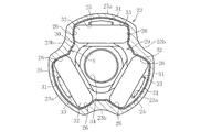
外側継手部材22は、有底筒状のカップ部(マウス部)23と、このマウス部23から突出するステム部24とからなる。ステム部24は端部に形成したスプラインまたはセレーション軸にて第1の回転軸(図示せず)とトルク伝達可能に結合する。マウス部23は、内周の円周方向三等分位置に軸方向に延びるトラック溝25が形成してある。マウス部23は、横断面で見て、大径部23aと小径部23bが交互に現れる非円筒形状である。すなわち、マウス部23は、大径部23aと小径部23bとを形成することによって、その内周面に、軸方向に延びる3本の前記トラック溝25が形成される。各トラック溝25の円周方向で向き合った側壁にローラ案内面26、26が形成される。
The
トリポード部材29は、ボス30と脚軸31とを備える。ボス30には第2の回転軸(シャフト)とトルク伝達可能に結合するスプラインまたはセレーション孔34が形成してある。脚軸31はボス30の円周方向三等分位置から半径方向に突出している。トリポード部材29の各脚軸31には、トルク伝達部材としてもローラ32が軸線(軸心)を中心として回転自在に外嵌されている。そして、各ローラ32は外側継手部材22のそれぞれのトラック溝25内に収容される。なお、脚軸31およびローラ32は、大径部23aの内周面33に接触させないようにしている。また、ローラ32として、内側ローラと外側ローラとを有するダブルローラタイプであっても、1個のみのシングルローラタイプであってもよい。
The
外側継手部材22の内径面には硬化層Sが形成されている。この硬化層Sは、浸炭焼入れにて形成することができる。浸炭焼入れとは、低炭素鋼または低炭素合金鋼を機械加工した後、その表面層に炭素量を増加させ、表面層のみを焼入硬化する処理法である。また、浸炭処理には、固体浸炭と、液体浸炭と、ガス浸炭と、真空浸炭とがある。固体浸炭は、大物部品の処理が可能で、少量生産向きであり、設備費が安い利点がある。液体浸炭は、小物部品の処理に有利で、薄い硬化層形成が可能であり、設備費が安い利点がある。ガス浸炭は、炭素濃度の調整が可能で、自動化が容易であり、多量生産向きである。真空浸炭は、作業環境が良好で、処理品の光輝性が良好であり、粒界酸化の面で有利である。
A hardened layer S is formed on the inner diameter surface of the
このため、この外側継手部材22の内径面には硬化層Sの形成には、前記種々の浸炭処理が可能であるが、特に、ガス浸炭が好ましい。これは、多量生産に向いているからである。この硬化層Sの厚さとしては、例えば、0.5mm〜2mm程度とするのが好ましい。すなわち、硬化層Sの肉厚を、外側継手部材22の肉厚の50%以下とすることが好ましい。
For this reason, in order to form the hardened layer S on the inner diameter surface of the outer
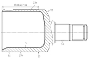
また、外側継手部材22の外径面に、防炭処理を施すことにより浸炭焼入れ硬化処理が行われない非硬化層S1を設けている。防炭処理とは、浸炭焼入れにおいて浸炭しないようにする処理である。防炭処理は、浸炭焼入れ処理を行いたくないない部位にメッキを施したり、浸炭処理を行った後、浸炭焼入れ処理を行いたくない部位の浸炭処理部を削ったり、防炭剤を塗布したりすることによってできる。
Moreover, the non-hardening layer S1 in which the carburization hardening hardening process is not performed by providing a carburizing prevention process is provided in the outer diameter surface of the outer
この実施形態では、非硬化層S1は図2の防炭範囲Hである。この防炭範囲Hは、トラック溝25内をトルク伝達手段であるローラ6が移動する軸方向範囲(内側継手部材を含むトルク伝達要素が移動する軸方向範囲)に対応する。なお、非硬化層S1とは、防炭処理を施すことにより浸炭焼入れ硬化処理を行うものであるので、この場合、硬化層S以外を非硬化層と呼ぶことができる。
In this embodiment, the non-hardened layer S1 is the carbon-proof range H of FIG. This carbon-proof range H corresponds to an axial range in which the
前記実施形態のように構成することによって、図4に示すように防炭処理を施していないものに比べて、静捩り強度や疲労強度が向上している。すなわち、防炭処理有り無しのみが相違する外側継手部材を製作して、同一条件で片振り捩り疲労試験をそれぞれについて複数回を行った場合、平均値で比較すると、防炭処理有りは防炭無しの約2.7倍の強度があった。 By comprising like the said embodiment, as shown in FIG. 4, the static torsional strength and the fatigue strength are improving compared with the thing which has not performed the carbon-proof process. That is, when outer joint members that differ only in the presence / absence of the carbon-proof treatment are manufactured, and the single swing torsional fatigue test is performed several times for each under the same conditions, when the average value is compared, with the carbon-proof treatment, It was about 2.7 times stronger than none.
また、防炭処理有り無しのみが相違する外側継手部材を製作して、同一条件で静捩り強度試験をそれぞれについて複数回を行った場合、平均値で比較すると、防炭処理有りは防炭無しの約1.3倍の強度があった。 In addition, when producing outer joint members that differ only in the presence / absence of charcoal-proofing treatment, and performing static torsional strength tests multiple times for each under the same conditions, when compared with the average value, there is no charcoal-proofing with carbonic acid-proofing treatment There was about 1.3 times the strength.
本発明では、内径面に浸炭焼入れ硬化処理が行われた硬化層Sを設けているので、内径面側において耐摩耗性に優れる。このため、トラック溝25内のトルク伝達手段(ローラ32)の移動による案内面26の摩耗を抑制することができる。また、外径面に、防炭処理を施すことにより浸炭焼入れ硬化処理が行われない非硬化層S1を設けているので、外径面側においては靭性に優れ、亀裂の発生を防止することができ、たとえ発生したとしてもその成長を抑制することができるとともに、この外側継手部材の静捩り強度や疲労強度を向上させることができる。
In the present invention, since the hardened layer S that has been subjected to carburizing and quenching hardening treatment is provided on the inner diameter surface, the wear resistance is excellent on the inner diameter surface side. For this reason, the wear of the
また、長手方向(軸方向)で機能上必要な部位のみに防炭処理を行うことができ、強度的に弱い所(応力集中部)に非硬化層S1を形成することになる。このため、外径面全域に亘っての防炭処理を行う必要がなく、製造時間の短縮及び低コスト化を図ることができる。 In addition, the carbon-proofing treatment can be performed only on functionally necessary parts in the longitudinal direction (axial direction), and the non-hardened layer S1 is formed in a place where the strength is weak (stress concentration part). For this reason, it is not necessary to carry out the carbon-proofing process over the entire outer diameter surface, and the manufacturing time can be shortened and the cost can be reduced.
硬化層Sの厚さとしては、例えば、0.5mm〜2mm程度とすることにより、外径面側における靭性がより優れることになり、亀裂の発生及び成長をより一層抑制でき、静捩り強度や疲労強度を確実に向上させることができる。 As the thickness of the hardened layer S, for example, by setting the thickness to about 0.5 mm to 2 mm, the toughness on the outer diameter surface side is further improved, crack generation and growth can be further suppressed, static torsion strength and The fatigue strength can be improved reliably.
以上、本発明の実施形態につき説明したが、本発明は前記実施形態に限定されることなく種々の変形が可能であって、例えば、非硬化層S1を外側継手部材の全長に亘って形成するようにしてもよい。また、前記実施形態では、硬化層Sを内径面の全周に亘って設けているが、ローラ32が接触する部分、つまり案内面26にのみに設けてもよい。
As described above, the embodiment of the present invention has been described. However, the present invention is not limited to the above-described embodiment, and various modifications are possible. For example, the non-hardened layer S1 is formed over the entire length of the outer joint member. You may do it. Moreover, in the said embodiment, although the hardened layer S is provided over the perimeter of an internal diameter surface, you may provide only in the part which the
前記実施形態では、トルク伝達手段がローラであるトリポード型等速自在継手用であったが、等速自在継手として、トルク伝達手段がボールである他の摺動型等速自在継手であってもよい。本発明では、内径面の硬化層Sが形成されるので、摺動型等速自在継手であれば、ローラ6等が転動するローラ案内面11の摩耗を抑制することができ、特に優れた効果を発揮することができるが、他の種々の固定型等速自在継手用であってもよい。
In the above embodiment, the torque transmission means is for a tripod type constant velocity universal joint that is a roller. However, the constant velocity universal joint may be another sliding type constant velocity universal joint in which the torque transmission means is a ball. Good. In the present invention, since the hardened layer S of the inner diameter surface is formed, if the sliding type constant velocity universal joint is used, it is possible to suppress the wear of the
25 トラック溝
26 ローラ案内面
S 硬化層
S1 非硬化層
25
Claims (2)
Priority Applications (1)
| Application Number | Priority Date | Filing Date | Title |
|---|---|---|---|
| JP2005355046A JP2007155100A (en) | 2005-12-08 | 2005-12-08 | Outside joint member for constant velocity universal joint |
Applications Claiming Priority (1)
| Application Number | Priority Date | Filing Date | Title |
|---|---|---|---|
| JP2005355046A JP2007155100A (en) | 2005-12-08 | 2005-12-08 | Outside joint member for constant velocity universal joint |
Publications (1)
| Publication Number | Publication Date |
|---|---|
| JP2007155100A true JP2007155100A (en) | 2007-06-21 |
Family
ID=38239730
Family Applications (1)
| Application Number | Title | Priority Date | Filing Date |
|---|---|---|---|
| JP2005355046A Withdrawn JP2007155100A (en) | 2005-12-08 | 2005-12-08 | Outside joint member for constant velocity universal joint |
Country Status (1)
| Country | Link |
|---|---|
| JP (1) | JP2007155100A (en) |
Cited By (1)
| Publication number | Priority date | Publication date | Assignee | Title |
|---|---|---|---|---|
| WO2013154015A1 (en) * | 2012-04-11 | 2013-10-17 | Ntn株式会社 | Inner member of constant velocity universal joint and method for producing same |
-
2005
- 2005-12-08 JP JP2005355046A patent/JP2007155100A/en not_active Withdrawn
Cited By (2)
| Publication number | Priority date | Publication date | Assignee | Title |
|---|---|---|---|---|
| WO2013154015A1 (en) * | 2012-04-11 | 2013-10-17 | Ntn株式会社 | Inner member of constant velocity universal joint and method for producing same |
| JP2013217478A (en) * | 2012-04-11 | 2013-10-24 | Ntn Corp | Inner member of constant velocity universal joint, and method for producing same |
Similar Documents
| Publication | Publication Date | Title |
|---|---|---|
| US7685717B2 (en) | Method for manufacturing a bearing raceway member | |
| KR100662220B1 (en) | Constant velocity universal joint | |
| EP2381120A1 (en) | Outer member of constant speed universal joint | |
| JP5045491B2 (en) | Large rolling bearing | |
| WO2022202922A1 (en) | Track wheel and shaft | |
| CN113195915B (en) | Tripod type constant velocity universal coupling | |
| JP2004116569A (en) | Rolling bearing | |
| JPH0154574B2 (en) | ||
| JP5598016B2 (en) | Manufacturing method of thrust trace of needle thrust bearing | |
| JP2006226412A (en) | Constant velocity universal joint, cage for constant velocity universal joint and its manufacturing method | |
| JP2007155100A (en) | Outside joint member for constant velocity universal joint | |
| JP3949863B2 (en) | Constant velocity universal joint | |
| JP2020079630A (en) | Cage for constant velocity universal joint, and constant velocity universal joint | |
| JP2007255461A (en) | Constant velocity universal joint | |
| JP2007239837A (en) | Tripod type constant velocity universal joint and its manufacturing method | |
| JP2005098450A (en) | Outside joint member of constant velocity universal joint and manufacturing method thereof | |
| CN117836530A (en) | Tripod type constant velocity universal coupling | |
| JP3949864B2 (en) | Constant velocity universal joint | |
| JP2009052656A (en) | Outer coupling member of constant velocity universal joint and manufacturing method of the same | |
| JP2007303502A (en) | Tripod member and tripodal constant velocity universal joint | |
| JP2007182607A (en) | Method for manufacturing rolling member for use in constant velocity joint, rolling member for use in constant velocity joint, and constant velocity joint | |
| JP7591060B2 (en) | Heat treatment method for a tubular shaft for a drive shaft having a ball spline structure and a tubular shaft manufactured thereby | |
| JP2008064158A (en) | Tripod type constant velocity universal joint | |
| JP2007211926A (en) | Inner member of constant velocity universal joint and its manufacturing method | |
| CN109154330A (en) | Carbonitriding of Universal Joint Cross Bushings |
Legal Events
| Date | Code | Title | Description |
|---|---|---|---|
| A300 | Withdrawal of application because of no request for examination |
Free format text: JAPANESE INTERMEDIATE CODE: A300 Effective date: 20090303 |