JP2007155149A - Blade driving device of swing resistor - Google Patents
Blade driving device of swing resistor Download PDFInfo
- Publication number
- JP2007155149A JP2007155149A JP2005347049A JP2005347049A JP2007155149A JP 2007155149 A JP2007155149 A JP 2007155149A JP 2005347049 A JP2005347049 A JP 2005347049A JP 2005347049 A JP2005347049 A JP 2005347049A JP 2007155149 A JP2007155149 A JP 2007155149A
- Authority
- JP
- Japan
- Prior art keywords
- blade
- swing
- shape memory
- memory alloy
- drive device
- Prior art date
- Legal status (The legal status is an assumption and is not a legal conclusion. Google has not performed a legal analysis and makes no representation as to the accuracy of the status listed.)
- Withdrawn
Links
Images



Classifications
-
- B—PERFORMING OPERATIONS; TRANSPORTING
- B60—VEHICLES IN GENERAL
- B60H—ARRANGEMENTS OF HEATING, COOLING, VENTILATING OR OTHER AIR-TREATING DEVICES SPECIALLY ADAPTED FOR PASSENGER OR GOODS SPACES OF VEHICLES
- B60H1/00—Heating, cooling or ventilating devices
- B60H1/00642—Control systems or circuits; Control members or indication devices for heating, cooling or ventilating devices
- B60H1/00814—Control systems or circuits characterised by their output, for controlling particular components of the heating, cooling or ventilating installation
- B60H1/00821—Control systems or circuits characterised by their output, for controlling particular components of the heating, cooling or ventilating installation the components being ventilating, air admitting or air distributing devices
- B60H1/00871—Air directing means, e.g. blades in an air outlet
-
- B—PERFORMING OPERATIONS; TRANSPORTING
- B60—VEHICLES IN GENERAL
- B60H—ARRANGEMENTS OF HEATING, COOLING, VENTILATING OR OTHER AIR-TREATING DEVICES SPECIALLY ADAPTED FOR PASSENGER OR GOODS SPACES OF VEHICLES
- B60H1/00—Heating, cooling or ventilating devices
- B60H1/34—Nozzles; Air-diffusers
- B60H1/3414—Nozzles; Air-diffusers with means for adjusting the air stream direction
- B60H1/3421—Nozzles; Air-diffusers with means for adjusting the air stream direction using only pivoting shutters
-
- B—PERFORMING OPERATIONS; TRANSPORTING
- B60—VEHICLES IN GENERAL
- B60H—ARRANGEMENTS OF HEATING, COOLING, VENTILATING OR OTHER AIR-TREATING DEVICES SPECIALLY ADAPTED FOR PASSENGER OR GOODS SPACES OF VEHICLES
- B60H1/00—Heating, cooling or ventilating devices
- B60H1/34—Nozzles; Air-diffusers
- B60H2001/3471—Details of actuators
Landscapes
- Physics & Mathematics (AREA)
- Thermal Sciences (AREA)
- Engineering & Computer Science (AREA)
- Mechanical Engineering (AREA)
- Air-Flow Control Members (AREA)
- Air-Conditioning For Vehicles (AREA)
Abstract
Description
本発明は、空調用通風路となるダクトの出口部分に揺動可能に軸支されたブレードを揺動させてダクト出口からの送風方向を変更するスイングレジスタのブレード駆動装置に関する。 The present invention relates to a blade drive device of a swing register that changes a blowing direction from a duct outlet by swinging a blade pivotally supported at an outlet portion of a duct serving as a ventilation passage for air conditioning.
車両等の空調装置では、その通風路(ダクト)の出口である送風口に縦ブレードおよび横ブレードをそれぞれ複数配設し、縦ブレードをアクチュエータにて左右に揺動(スイング動作)させて風向を変更するスイングレジスタが用いられている。従来、特許文献1〜4に見られるように、そうしたスイングレジスタのブレード駆動用のアクチュエータとしては通常、モータを用いるのが一般的となっている。 In an air conditioner such as a vehicle, a plurality of vertical blades and horizontal blades are arranged at an air outlet that is an outlet of the ventilation path (duct), and the vertical blades are swung left and right (swinging) by an actuator to change the wind direction. A swing register to be changed is used. Conventionally, as seen in Patent Documents 1 to 4, a motor is generally used as an actuator for driving a blade of such a swing register.
図7に、ブレード駆動用のアクチュエータとしてDCモータを採用する従来のスイングレジスタのブレード駆動装置の一例を示す。同図に示すように、回転軸力を発生するDCモータ50の出力軸50aは、複数のギアにより構成された減速機構51に連結されている。減速機構51の最終ギア51aは、回転運動を振幅運動に変換するクランク機構52に連結されている。クランク機構52には、先端にラックギア53が一体に振幅動作に固定されたロッドワイヤ54が連結されるとともに、そのラックギア53を介して第1ピニオンギア55aに駆動連結されている。そしてこの第1ピニオンギア55aの回転軸に同軸を有して回転可能に軸支された第2ピニオンギア55bには、ブレード57の揺動軸57aが一体回転可能に固定されたギア56が噛み合わされている。なお、第1および第2ピニオンギア55a,55bは、ばねにより互いに押圧された状態で配設されており、摩擦力を介して回転力を伝達可能とするとともに、車両搭乗者の手動操作によるブレード57の強制揺動時には互いの相対回動を許容するクラッチ機構として機能するように構成されている。
ところで、上記従来のようなブレード駆動用アクチュエータとしてモータを採用するスイングレジスタでは、モータや減速機構等の動作音が車室内に漏洩するため、モータの周囲をゴム等の遮音材料で覆ったり、モータおよび減速機構をケース内に収容したり、といった遮音対策が必要となっていた。そしてその分、部品点数が増加して製造コストの増大や装置の大型化を招くという問題があった。 By the way, in a swing register that employs a motor as the conventional blade driving actuator, the operation sound of the motor, the speed reduction mechanism, etc. leaks into the vehicle interior, so the motor is covered with a sound insulation material such as rubber or the motor. In addition, sound insulation measures such as housing the speed reduction mechanism in the case have been required. As a result, there is a problem that the number of parts increases, leading to an increase in manufacturing cost and an increase in size of the apparatus.
本発明は、こうした実状に鑑みてなされたものであって、その解決しようとする課題は、ブレードの駆動に伴う騒音をより容易且つ的確に低減することのできるスイングレジスタを提供することにある。 The present invention has been made in view of such a situation, and a problem to be solved is to provide a swing register that can more easily and accurately reduce noise associated with driving of a blade.
上記課題を解決するため、請求項1に記載の発明では、空調用通風路の出口に揺動可能に軸支されたブレードを揺動させて前記出口からの送風方向を変更するスイングレジスタのブレード駆動装置において、通電加熱により伸縮する形状記憶合金を備えるとともに、その形状記憶合金の伸縮に応じて前記ブレードが揺動されるように同形状記憶合金と前記ブレードとを駆動連結するようにした。 In order to solve the above-mentioned problems, in the invention according to claim 1, the blade of the swing register that swings the blade pivotally supported at the outlet of the air-conditioning ventilation passage so as to change the blowing direction from the outlet. The drive device includes a shape memory alloy that expands and contracts by energization heating, and the shape memory alloy and the blade are drivingly connected so that the blade swings according to the expansion and contraction of the shape memory alloy.
上記構成では、通電加熱に伴う形状記憶合金の伸縮によってブレードが揺動され、空調用通風路の出口からの送風方向が変更されるようになる。こうした構成では、それ自体には動作音を伴わない形状記憶合金の通電加熱による伸縮を利用してブレードを揺動させているため、ブレードの駆動に伴う騒音をより容易且つ的確に低減することができる。 In the said structure, a braid | blade is rock | fluctuated by the expansion / contraction of the shape memory alloy accompanying energization heating, and the ventilation direction from the exit of the ventilation path for an air conditioning comes to be changed. In such a configuration, since the blade is swung by using the expansion and contraction of the shape memory alloy that does not accompany the operation sound by the current heating, the noise accompanying the driving of the blade can be reduced more easily and accurately. it can.
なお、請求項1に記載のスイングレジスタのブレード駆動装置は、請求項2に記載のように、形状記憶合金を2つ設けるとともに、その一方の通電加熱により前記ブレードを一方の方向に揺動させ、他方の通電加熱により前記ブレードをもう一方向に揺動させるように構成することができる。この場合、ブレードの上下、或いは左右といった双方向へのスイング動作がいずれも、通電加熱による形状記憶合金の伸縮によって行われるようになる。そのため、ブレードのスイング速度や送風方向の調整をより容易且つ的確に行うことが可能となる。 The blade drive device of the swing register according to claim 1 is provided with two shape memory alloys as described in claim 2, and swings the blade in one direction by energizing and heating one of them. The blade can be made to swing in the other direction by the other energization heating. In this case, bi-directional swing movements such as up and down or left and right of the blade are performed by expansion and contraction of the shape memory alloy by energization heating. Therefore, it becomes possible to adjust the blade swing speed and the blowing direction more easily and accurately.
更にそうした請求項2に記載のスイングレジスタのブレード駆動装置において、請求項3に記載のように上記2つの形状記憶合金に交互に通電する通電制御手段を備えるようにすれば、ブレードを繰り返し周期的にスイング動作させることができる。 Further, in the swing register blade drive device according to claim 2, if the power supply control means for alternately energizing the two shape memory alloys as described in claim 3 is provided, the blade is periodically and periodically rotated. Can be swung.
なお、以上に記載したスイングレジスタのブレード駆動装置は、請求項4に記載のように、ブレードの揺動軸に同期回動可能に連結されたロータの側周に細線状に形成された形状記憶合金を巻き掛けるとともに、その形状記憶合金の端部を上記ロータの側周に固定した構成とすることができる。この場合、形状記憶合金の収縮が直接的に回動運動に変換されることから、ラック・アンド・ピニオン等の直動回動変換機構を設けずともブレードを回動可能となり、部品点数が低減されるようになる。 In the swing register blade drive device described above, the shape memory formed in a thin line shape on the side periphery of the rotor connected to the swing shaft of the blade so as to be able to rotate synchronously is provided. While winding an alloy, it can be set as the structure which fixed the edge part of the shape memory alloy to the side periphery of the said rotor. In this case, since the contraction of the shape memory alloy is directly converted into a rotational motion, the blade can be rotated without providing a linear motion rotation conversion mechanism such as a rack and pinion, thereby reducing the number of parts. Will come to be.
ちなみに、上記各構成のスイングレジスタのブレード駆動装置に採用される形状記憶合金としては、例えば請求項5に記載のようなチタン・ニッケル系の合金を使用することができる。 Incidentally, as the shape memory alloy employed in the blade drive device of the swing register having the above-described configuration, for example, a titanium / nickel alloy as described in claim 5 can be used.
本発明のスイングレジスタのブレード駆動装置によれば、それ自体には動作音を伴わない形状記憶合金の通電加熱による伸縮を利用してブレードを駆動するようにしているため、ブレードの駆動に伴う騒音をより容易且つ的確に低減することができる。 According to the blade drive device of the swing register of the present invention, since the blade is driven by utilizing the expansion and contraction of the shape memory alloy that does not accompany the operation sound by energization heating, the noise accompanying the drive of the blade Can be reduced more easily and accurately.
以下、本発明を具体化したスイングレジスタのブレード駆動装置の一実施形態を、図1〜図5を参照して詳細に説明する。
本実施形態のスイングレジスタのブレード駆動装置は、車載空調装置の送風通路(ダクト)の出口部分に設置され、その出口部分に配設された縦および横のブレードのうち、縦レジスタを左右に揺動、すなわちスイング動作させることで車室への送風方向を左右に変更するように構成されている。
Hereinafter, an embodiment of a swing register blade driving apparatus embodying the present invention will be described in detail with reference to FIGS.
The blade drive device of the swing register of the present embodiment is installed at the outlet portion of the ventilation passage (duct) of the on-vehicle air conditioner, and among the vertical and horizontal blades arranged at the outlet portion, the vertical register is swung left and right. It is configured to change the air blowing direction to the passenger compartment by moving or swinging.
本実施形態では、こうしたスイングレジスタの縦ブレードのスイング動作を、通電加熱に伴う形状記憶合金(SMA:Shape Memory Alloy)の収縮を利用して行うようにしている。ここでは形状記憶合金として、細線状のチタン・ニッケル系合金を用いている。こうした形状記憶合金を用いて縦ブレードを駆動する本実施形態のスイングレジスタのブレード駆動装置では、それ自体には動作音を伴わない形状記憶合金の通電加熱による収縮を利用して縦ブレードが駆動されることから、格別な遮音対策を行わずとも、縦ブレードの駆動に伴う騒音を容易且つ的確に低減することができる。そしてその結果、遮音部材の設置が不要となることから、ブレード駆動装置の軽量化、省スペース化、部品点数の削減なども併せ図られるようになっている。 In this embodiment, the swing operation of the vertical blades of the swing register is performed by utilizing the contraction of a shape memory alloy (SMA) that accompanies heating with current. Here, a fine-line titanium-nickel alloy is used as the shape memory alloy. In the swing register blade driving device of this embodiment that drives the vertical blade using such a shape memory alloy, the vertical blade is driven by utilizing the contraction of the shape memory alloy that is not accompanied by an operation sound by current heating. Therefore, it is possible to easily and accurately reduce the noise accompanying the driving of the vertical blades without taking any special measures against sound insulation. As a result, it is not necessary to install a sound insulation member, so that the blade drive device can be reduced in weight, space-saving, and the number of parts can be reduced.
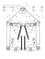
図1に、そうした本実施形態のスイングレジスタのブレード駆動装置の全体構造を示す。なお以下の説明では、このブレード駆動装置において、車載空調装置の送風通路(ダクト)の出口側を同駆動装置の前方と記載し、その反対側を同駆動装置の後方と記載する。 FIG. 1 shows the overall structure of the swing register blade driving device of this embodiment. In the following description, in this blade driving device, the outlet side of the air passage (duct) of the in-vehicle air conditioner is described as the front of the driving device, and the opposite side is described as the rear of the driving device.
車載空調装置の送風通路(ダクト)の出口には、上下方向に揺動可能に軸支された複数の横ブレード(図示略)とともに、揺動軸11を中心に左右に揺動(スイング動作)可能に軸支された複数(同図では5つ)の縦ブレード10a〜10eが配設されている。羽根状に形成された各縦ブレード10a〜10eは、リンク機構12を介して互いに機械的に連結されており、一体となって同期してスイング動作されるようになっている。
A plurality of horizontal blades (not shown) pivotally supported so as to be able to swing in the vertical direction are swung left and right around the swing shaft 11 (swing operation) at the outlet of the air passage (duct) of the in-vehicle air conditioner. Plural (five in the figure)
これら縦ブレード10a〜10eのうち、中央に配設された縦ブレード10cの揺動軸11には、一体回動可能にロータ13が固定されている。略円柱状に形成されたロータ13の側周には、細線状に形成されたチタン・ニッケル系の形状記憶合金からなる2本のワイヤ、すなわち左SMAワイヤ14Lおよび右SMAワイヤ14Rの端部がそれぞれ固定されている。左SMAワイヤ14Lは、固定された端部からロータ13の側周に同図の反時計回りに巻き掛けられた後、同ロータ13の左後方に向けて導出されている。一方、右SMAワイヤ14Rは、固定された端部からロータ13の側周に同図の時計回りに巻き掛けられた後、同ロータ13の右後方に向けて導出されている。なお、ロータ13の回動範囲は、図示しないストッパによって適宜な範囲に制限されている。
Of these
ロータ13から導出された左右のSMAワイヤ14L,14Rは、ロータ13の左右後方に各配設された固定プーリ15L,15Rにそれぞれ巻き掛けられている。回動可能に軸支されたこれらの固定プーリ15L,15Rから駆動装置後方に向けて導出された左右のSMAワイヤ14L,14Rは、緩み防止用の可動プーリ16L,16Rにそれぞれ巻き掛けられている。可動プーリ16L,16Rは、揺動アーム18L,18Rの一端に回動可能に軸支された状態で、上記固定プーリ15L,15Rの駆動装置後方に配設されている。各揺動アーム18L,18Rは、その略中央において揺動可能に軸支されるとともに、それらの可動プーリ16L,16Rの軸支された側とは反対側の端部にコイルばね19L,19Rが伸張状態でそれぞれ固定されている。そしてそれらコイルばね19L,19Rの弾性反発力によって各揺動アーム18L,18Rは、可動プーリ16L,16Rを駆動装置後方に引き下げる方向に揺動される側に常時付勢されている。そして各SMAワイヤ14L,14Rが伸張すると、コイルばね19L,19Rの弾性反発力によって、可動プーリ16L,16Rを駆動装置後方に引き下げるように揺動アーム18L,18Rが揺動するようになる。そしてその結果、各SMAワイヤ14L,14Rの張り渡し長が伸張されて、各SMAワイヤ14L,14Rの緩みが防止されるようになっている。なお、各揺動アーム18L,18Rの駆動装置前方には、ストッパ17L,17Rが配設されている。そしてそれらストッパ17L,17Rと各揺動アーム18L,18Rとの当接により、可動プーリ16L,16Rを駆動装置前方に押し上げる側に向けての各揺動アーム18L,18Rの揺動の範囲が制限されるようになっている。
The left and right SMA wires 14 </ b> L and 14 </ b> R led out from the
こうした緩み防止用の可動プーリ16L,16Rから駆動装置前方に向けて導出された両SMAワイヤ14L,14Rの端部は、それらSMAワイヤ14L,14Rの過熱時に強制的に通電を遮断する強制通電遮断機構20L,20Rの揺動アーム21L,21Rにそれぞれ固定されている。各強制通電遮断機構20L,20Rの揺動アーム21L,21Rは、その略中央において揺動可能に軸支され、その一端にSMAワイヤ14L,14Rの端部が固定されるとともに、他端にコイルばね23L,23Rが伸張状態で固定されている。SMAワイヤ14L,14Rの端部の固定された側の各揺動アーム21L,21Rの端部の駆動装置前方側には、SMAワイヤ14L,14Rと電気的に接続された可動電極24L,24Rが突出して設けられている。また各揺動アーム21L,21Rは、上記コイルばね23L,23Rの弾性反発力によって、SMAワイヤ14L,14Rの固定端を駆動装置前方に押し上げる方向に揺動される側に常時付勢されている。そしてその付勢によって各可動電極24L,24Rは、各揺動アーム18L,18Rの駆動装置前方に固定された板状の固定電極25L,25Rに押圧されている。
The ends of both
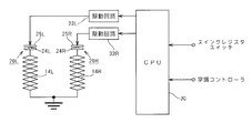
図2は、本実施形態のスイングレジスタのブレード駆動装置の電気的構成を示している。同図に示すように、各SMAワイヤ14L,14Rの通電制御を司る中央演算処理装置(CPU)30には、車室内に設けられたスイングレジスタスイッチが電気的に接続されるとともに、車載空調装置の全体的な制御を司る空調コントローラからの指令信号が入力されるようになっている。ブレード駆動装置による縦ブレード10a〜10e(図1参照)の自動スイング動作は、スイングレジスタスイッチの閉(オン)操作に応じて許可され、その開(オフ)操作に応じて禁止される。また空調コントローラは、外気や車室内の温度の検出結果や車両搭乗者の操作に応じて送風温度や送風量を決定して空調装置を制御するとともに、縦ブレード10a〜10e(図1参照)のスイング動作態様を決定してCPU30に指令する。
FIG. 2 shows an electrical configuration of the swing register blade driving device of the present embodiment. As shown in the figure, a central processing unit (CPU) 30 that controls energization of the
またCPU30には、各SMAワイヤ14L,14Rの駆動回路33L、33Rが接続されている。これらの駆動回路33L,33Rは、CPU30からの指令に基づいて各々対応するSMAワイヤ14L,14Rに対する通電を実行する。各SMAワイヤ14L,14Rはそれぞれ、上記強制通電遮断機構20L,20Rの可動電極24L,24Rと固定電極25L,25Rとの接点を介して駆動回路33L,33Rに電気的に接続されるとともに、上記ロータ13(図1参照)側の端部にて接地されている。
The
さて以上のように構成された本実施形態のスイングレジスタのブレード駆動装置では上述したように、細線状に形成されたチタン・ニッケル系の形状記憶合金からなるSMAワイヤ14L,14Rの通電加熱による収縮を利用して縦ブレード10a〜10eをスイング動作させるようにしている。ここで採用するSMAワイヤ14L,14Rは、形状回復時の変形の方向がその長さ方向、すなわち伸縮方向に限定されるように、素材の組織構造に異方性を持たせて形成されている。こうしたSMAワイヤ14L,14Rは、冷却すれば柔らかく弛緩して外力による引っ張りに応じて弾性的に伸張する一方、加熱すれば形状回復により収縮して硬化する。図3に、こうしたSMAワイヤ14L,14Rの温度−ひずみ線図の一例を示す。同図に示すようにSMAワイヤ14L,14Rは、加熱時には約80℃から収縮を開始するとともに、冷却時には約75℃から弛緩、伸張し始める。こうしたSMAワイヤ14L,14Rの収縮の開始温度、および弛緩−伸張の開始温度は、合金の成分調整によりある程度変更することが可能となっている。なお、SMAワイヤ14L,14Rは比較的大きい電気抵抗を有しており、通電により容易に加熱することができるようになっている。ちなみに、上記のような細線状のチタン・ニッケル系形状記憶合金からなるSMAワイヤ14L,14Rとしては、通電加熱による形状回復を通じて、最大で全長の5%以上の運動ひずみを安定して繰り返し発生可能なものが開発され、実用されている。
In the swing register blade drive apparatus of the present embodiment configured as described above, as described above, the
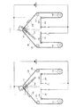
続いて、こうしたSMAワイヤ14L,14Rの通電加熱に伴う収縮を利用して縦ブレードをスイング動作させる本実施形態のスイングレジスタのブレード駆動装置の動作原理を説明する。図4(a)に示すように、左SMAワイヤ14Lにのみ通電を行うと、その通電により加熱された左SMAワイヤ14Lが収縮するとともに、非加熱、すなわち冷却状態にある右SMAワイヤ14Rが弛緩して、引っ張りにより弾性的に伸張可能となることから、ロータ13は図中反時計回りに回動されるようになる。そしてその結果、ロータ13に一体化移動可能に揺動軸11の固定された縦ブレード10cが図中反時計回りにスイング動作されるようになる。一方、図4(b)に示すように、右SMAワイヤ14Rのみに通電を行うと、その通電により加熱された右SMAワイヤ14Rが収縮するとともに、冷却状態の左SMAワイヤ14Lが弛緩して弾性伸張可能となることから、ロータ13が図中時計回りに回動される。そしてその結果、そのロータ13に一体化移動可能に揺動軸11の固定された縦ブレード10cが図中時計回りにスイング動作されるようになる。従って、左右のSMAワイヤ14L,14Rに交互に通電すれば、縦ブレード10cを周期的に左右交互にスイング動作させることができる。また収縮ひずみ率が適宜に維持されるように左右いずれか一方のSMAワイヤ14L,14Rに対する通電を適宜に継続すれば、縦ブレード10cのスイング角を保持し、ダクト出口からの送風方向を所望とする方向に固定することが可能にもなる。
Next, the principle of operation of the blade driving device of the swing register of this embodiment that swings the vertical blade by utilizing the contraction accompanying the energization heating of the
ところで、このようにSMAワイヤ14L,14Rを駆動源として利用するスイングレジスタのブレード駆動装置では、SMAワイヤ14L,14Rが過剰通電されると、SMAワイヤ14L,14Rが適正な使用温度範囲の上限を超えて過熱してしまうことがある。そして過熱状態が継続されると、自身の収縮力でSMAワイヤ14L,14Rに伸びなどの永久ひずみが残留してしまい、その形状回復特性が悪化するようになる。そしてその結果、縦ブレード10a〜10eを適正に揺動させることができなくなってしまうおそれがある。そのため、本実施形態では、過熱によりSMAワイヤ14L,14Rが過剰収縮したときには、上述した強制通電遮断機構20L,20Rにより、通電を強制的に遮断して、過熱状態の継続を回避するようにしている。
By the way, in the swing register blade drive device using the
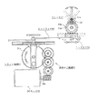
こうした強制通電遮断機構20L,20Rのより具体的な動作態様を、図5(a)及び(b)を併せ参照して説明する。なお同図(a),(b)では、左側の強制通電遮断機構20Lの動作態様が示されているが、右側の強制通電遮断機構20Rについてもその動作態様は同様となっている。
More specific operation modes of the forced
非過熱時には、図5(a)に示すように、強制通電遮断機構20R(20L)の揺動アーム21R(21L)の一端に設けられた可動電極24R(24L)は、同揺動アーム21R(21L)の他端に伸張状態で固定されたコイルばね23R(23L)の弾性反発力によって、板状の固定電極25R(25L)に押圧されて当接されている。そしてその可動電極24R(24L)と固定電極25R(25L)との接点を通じて、SMAワイヤ14R(14L)の通電経路が維持されるようになる。なお、コイルばね23R(23L)の弾性反発力により揺動アーム21R(21L)に付与されるモーメントは、SMAワイヤ14R(14L)に印加される張力の許容範囲の上限となる張力(許容最大張力)がSMAワイヤ14R(14L)に加えられたときにその張力により揺動アーム21R(21L)に付与されるモーメントよりも若干小さく設定されている。そのため、非過熱時には、通電加熱によるSMAワイヤ14R(14L)の収縮がコイルばね23R(23L)の収縮およびその収縮に伴う揺動アーム21R(21L)の揺動により吸収されることはないようになっている。
At the time of non-overheating, as shown in FIG. 5A, the
一方、過熱によってSMAワイヤ14R(14L)が過剰収縮すると、ロータ13(図1等参照)の回動がストッパにより規制されてそれ以上の収縮が制限されることから、SMAワイヤ14R(14L)の張力Ftが増大するようになる。そしてその張力Ftが上記許容最大張力の近傍まで増大すると、図5(b)に示すように揺動アーム21R(21L)は、コイルばね23R(23L)の弾性反発力により付与されるモーメントに抗して揺動し、可動電極24R(24L)が固定電極25R(25L)から離間する。そしてその結果、SMAワイヤ14R(14L)への通電経路が切断され、通電が強制的に遮断されるようになる。
On the other hand, if the
以上説明した本実施形態のスイングレジスタのブレード駆動装置によれば、以下のような効果を得ることができる。
(1)本実施形態では、それ自体には動作音を伴わない形状記憶合金(SMAワイヤ14L,14R)の通電加熱による収縮を利用して縦ブレード10a〜10eを駆動させているため、縦ブレード10a〜10eの駆動に伴う騒音をより容易且つ的確に低減することができる。またその結果、遮音部材の設置が不要となり、ブレード駆動装置の軽量化や省スペース化が図られるようにもなる。
According to the swing register blade driving device of the present embodiment described above, the following effects can be obtained.
(1) In the present embodiment, the
(2)SMAワイヤ14L,14Rが過熱して過剰収縮すると、その収縮力にて可動電極24L,24Rが固定電極25L,25Rから離間して、自律的にSMAワイヤ14L,14Rへの通電が強制遮断されるようになっている。そのため、過熱によるSMAワイヤ14L,14Rの形状回復特性の悪化を、ひいてはスイングレジスタのブレード駆動装置の動作特性の悪化を好適に回避することができる。
(2) When the
(3)縦ブレード10cの揺動軸11に一体回動可能に連結されたロータ13の側周にSMAワイヤ14L,14Rを巻き掛けるとともに、それらSMAワイヤ14L,14Rの端部を同ロータ13の側周に固定した構造としているため、SMAワイヤ14L,14Rの収縮を直接的に揺動軸11の回動運動に変換することができる。そのため、ラック・アンド・ピニオンなどの直動回動変換機構を設けずとも、縦ブレード10a〜10eを容易にスイング動作させることができる。
(3) The
(4)車両搭乗者の手動操作による縦ブレード10cの強制揺動をSMAワイヤ14L,14Rの弾性変形による伸びによって吸収することができるため、従来のDCモータ駆動のブレード駆動装置に採用されるようなクラッチ機構を割愛することができるようにもなる。
(4) Since the forced swinging of the
(5)左右2本のSMAワイヤ14L,14Rの通電制御を通じて、容易且つ的確に縦ブレード10a〜10eのスイング動作を調整することができる。
なお、上記実施形態は以下のように変更して実施することもできる。
(5) The swing operation of the
In addition, the said embodiment can also be changed and implemented as follows.
・上記実施形態では、それぞれ縦ブレード10a〜10eの左方向および右方向への揺動を左右のSMAワイヤ14L,14Rの通電加熱による収縮でそれぞれ行うようにしていたが、左右のいずれかに対する縦ブレード10a〜10eの揺動のみをSMAワイヤの収縮力で行い、もう一方に対する揺動はばねの弾性反発力で行うようにブレード駆動装置を構成することもできる。例えば図6に示されるスイングレジスタのブレード駆動装置では、右SMAワイヤ14Rの代わりに、形状記憶合金でない通常の金属製のワイヤ40の端部がロータ13の側周に巻き掛けられた状態で固定されている。またロータ13から導出されたこのワイヤ40の先端には、一端が車体側に固定されたコイルばね41が連結されている。このコイルばね41のばね力は、通電加熱よりSMAワイヤ14Lの発生する収縮力よりも十分に小さく設定されている。こうしたスイングレジスタのブレード駆動装置では、SMAワイヤ14Lを通電加熱により収縮させると、コイルばね41のばね力に抗してロータ13が縦ブレード10cと共に図中反時計回りに回動する。ここで通電を遮断してSMAワイヤ14Lを冷却すると、同SMAワイヤ14Lが弛緩するとともにコイルばね41のばね力にて弾性的に伸び変形することから、ロータ13が縦ブレード10cと共に図中反時計回りに回動する。そのため、こうした構成においても、上記実施形態と同様に縦ブレード10a〜10eをスイング動作させることができる。なおこうした構成においても、それ自体には動作音を伴わないSMAワイヤ14Lの通電加熱による収縮、およびコイルばね41のばね力による冷却時の同SMAワイヤ14Lの伸張を通じて縦ブレード10cが左右にスイング動作されるため、縦ブレード10cの駆動に伴う騒音をより容易且つ的確に低減することは同様に可能である。
In the above embodiment, the
・上記実施形態では、SMAワイヤ14L,14Rの過熱を防止すべく通電を強制遮断する強制通電遮断機構20L,20Rを設けていたが、SMAワイヤ14L,14Rの過通電の防止回路を設置するなどにより、そうした強制通電遮断機構20L,20Rが特に必要とされない場合には、これを割愛するようにしても良い。
In the above embodiment, the forced
・上記実施形態では、ロータ13を縦ブレード10cの揺動軸11に一体に固定するようにしていたが、ギア等の動力伝達機構を用いてロータ13と縦ブレード10cの揺動軸11とを同期回動可能に駆動連結するようにしても良い。
In the above embodiment, the
・上記実施形態では、SMAワイヤ14L,14Rをロータ13の側周に巻き掛け、固定することで、SMAワイヤ14L,14Rの収縮による直線運動を直接的にロータ13の回動運動、ひいては縦ブレード10cの揺動運動に変換するようにしていたが、そうした直線運動から揺動運動への変換を別の機構により行うようにすることもできる。例えばSMAワイヤ14L,14Rの収縮によりラックを振幅運動させるとともに、縦ブレード10cの揺動軸11に同期回動可能に連結されたピニオンをそのラックに噛み合わせることで、縦ブレード10cを揺動させるように構成することができる。
In the above embodiment, the
・上記実施形態では、細線状に形成された形状記憶合金であるSMAワイヤ14L,14Rを用いて縦ブレード10cを揺動させていたが、これに代えてコイル状等の他の形状に形成された形状記憶合金を用いて縦ブレード10cを揺動させるようにすることもできる。要は、通電加熱により収縮する形状記憶合金を用い、その形状記憶合金の収縮に応じてブレードが揺動されるように形状記憶合金とブレードとを駆動連結する構成とされていれば、低騒音でのブレード駆動が可能なスイングレジスタのブレード駆動装置を具現とすることができる。
In the above embodiment, the
・通電加熱による形状回復で十分に大きい収縮量および収縮力を発生可能な形状記憶合金であれば、チタン・ニッケル系以外の形状記憶合金をブレードの駆動源として採用するようにしても良い。 As long as it is a shape memory alloy that can generate a sufficiently large shrinkage amount and shrinkage force by shape recovery by energization heating, a shape memory alloy other than a titanium / nickel-based alloy may be employed as a blade drive source.
・本発明に係るスイングレジスタのブレード駆動装置は、横ブレードを上下方向へのスイング動作させるための装置として実現することもできる。 The blade driving device for a swing register according to the present invention can also be realized as a device for swinging a horizontal blade in the vertical direction.
10a〜10e…縦ブレード、11…揺動軸、12…リンク機構、13…ロータ、14L,14R…形状記憶合金(SMA)ワイヤ、15L,15R…固定プーリ、16L,16R…可動プーリ、17L,17R…ストッパ、18L,18R…揺動アーム、19L,19R…コイルばね、20L,20R…強制通電遮断機構(21L,21R…揺動アーム、23L,23R…コイルばね、24L,24R…可動電極、25L,25R…固定電極)、30…中央演算処理装置(CPU)、33L,33R…駆動回路、40…ワイヤ、41…コイルばね、50…DCモータ、51…減速機構、51a…最終ギア、52…クランク機構、53…ラックギア、54…ロッドワイヤ、55a…第1ピニオンギア、55b…第2ピニオンギア。 10a to 10e ... vertical blades, 11 ... oscillating shaft, 12 ... link mechanism, 13 ... rotor, 14L, 14R ... shape memory alloy (SMA) wire, 15L, 15R ... fixed pulley, 16L, 16R ... movable pulley, 17L, 17R: Stopper, 18L, 18R ... Swing arm, 19L, 19R ... Coil spring, 20L, 20R ... Forced current cut-off mechanism (21L, 21R ... Swing arm, 23L, 23R ... Coil spring, 24L, 24R ... Movable electrode, 25L, 25R ... fixed electrode), 30 ... central processing unit (CPU), 33L, 33R ... drive circuit, 40 ... wire, 41 ... coil spring, 50 ... DC motor, 51 ... speed reduction mechanism, 51a ... last gear, 52 ... Crank mechanism, 53 ... rack gear, 54 ... rod wire, 55a ... first pinion gear, 55b ... second pinion gear.
Claims (5)
通電加熱により伸縮する形状記憶合金を備えるとともに、その形状記憶合金の伸縮に応じて前記ブレードが揺動されるように同形状記憶合金と前記ブレードとを駆動連結した
ことを特徴とするスイングレジスタのブレード駆動装置。 In a swing register blade drive device that changes the air blowing direction from the outlet by swinging the blade pivotally supported at the outlet of the air-conditioning ventilation passage,
A swing register comprising a shape memory alloy that expands and contracts by energization heating, and the shape memory alloy and the blade are drivingly connected so that the blade swings according to the expansion and contraction of the shape memory alloy. Blade drive device.
請求項1に記載のスイングレジスタのブレード駆動装置。 2. The swing register according to claim 1, wherein two shape memory alloys are provided, the blade is swung in one direction by one energization heating, and the blade is swung in another direction by the other energization heating. Blade drive device.
請求項2に記載のスイングレジスタのブレード駆動装置。 The swing register blade drive device according to claim 2, further comprising an energization control unit configured to energize the two shape memory alloys alternately.
ことを特徴とする請求項1〜3のいずれか1項に記載のスイングレジスタのブレード駆動装置。 The shape memory alloy formed in the shape of a thin wire is wound around the side periphery of the rotor that is connected to the swing shaft of the blade so as to be able to rotate synchronously, and the end of the shape memory alloy is fixed to the side periphery of the rotor The blade drive device of a swing register according to any one of claims 1 to 3, wherein the blade drive device is a swing register.
請求項1〜4のいずれか1項に記載のスイングレジスタのブレード駆動装置。 The swing drive blade drive device according to any one of claims 1 to 4, wherein the shape memory alloy is a titanium-nickel alloy.
Priority Applications (2)
| Application Number | Priority Date | Filing Date | Title |
|---|---|---|---|
| JP2005347049A JP2007155149A (en) | 2005-11-30 | 2005-11-30 | Blade driving device of swing resistor |
| US11/604,883 US20070123158A1 (en) | 2005-11-30 | 2006-11-28 | Louver driver for swing register |
Applications Claiming Priority (1)
| Application Number | Priority Date | Filing Date | Title |
|---|---|---|---|
| JP2005347049A JP2007155149A (en) | 2005-11-30 | 2005-11-30 | Blade driving device of swing resistor |
Publications (1)
| Publication Number | Publication Date |
|---|---|
| JP2007155149A true JP2007155149A (en) | 2007-06-21 |
Family
ID=38088144
Family Applications (1)
| Application Number | Title | Priority Date | Filing Date |
|---|---|---|---|
| JP2005347049A Withdrawn JP2007155149A (en) | 2005-11-30 | 2005-11-30 | Blade driving device of swing resistor |
Country Status (2)
| Country | Link |
|---|---|
| US (1) | US20070123158A1 (en) |
| JP (1) | JP2007155149A (en) |
Cited By (1)
| Publication number | Priority date | Publication date | Assignee | Title |
|---|---|---|---|---|
| JP2020173387A (en) * | 2019-04-12 | 2020-10-22 | エーエーシー コミュニケーション テクノロジーズ(ジョウシュウ)カンパニーリミテッド | Optical element drive, camera and portable electronic equipment |
Families Citing this family (16)
| Publication number | Priority date | Publication date | Assignee | Title |
|---|---|---|---|---|
| US8086352B1 (en) * | 2007-10-04 | 2011-12-27 | Scott Elliott | Predictive efficient residential energy controls |
| US8414366B2 (en) * | 2008-10-20 | 2013-04-09 | GM Global Technology Operations LLC | Active material enabled pressure release valves and methods of use |
| US8821224B2 (en) * | 2009-06-26 | 2014-09-02 | GM Global Technology Operations LLC | Shape memory alloy active hatch vent |
| FR2960829B1 (en) * | 2010-06-04 | 2012-07-13 | Faurecia Interieur Ind | AIR OUTPUT DEVICE FOR MOTOR VEHICLE COMPRISING A DEFLECTOR |
| US8876579B2 (en) * | 2011-01-14 | 2014-11-04 | GM Global Technology Operations LLC | Shape memory alloy actuated HVAC outlet airflow baffle controllers |
| US20130037252A1 (en) * | 2011-08-12 | 2013-02-14 | GM Global Technology Operations LLC | Smart hvac system having occupant detection capability |
| US8881766B2 (en) | 2011-10-03 | 2014-11-11 | Hamon Research-Cottrell, Inc. | Damper assembly |
| US9457907B2 (en) * | 2013-04-15 | 2016-10-04 | The Boeing Company | Direction controlled service apparatus |
| AU2016204260B2 (en) | 2015-06-25 | 2021-04-08 | Hunter Douglas Inc. | Shutter assembly with motorized louver drive system |
| DE202016103388U1 (en) * | 2016-06-27 | 2016-07-06 | GRAMMER Interior Components GmbH | air vents |
| US10407977B2 (en) | 2016-12-28 | 2019-09-10 | Hunter Douglas Inc. | Motorized shutter assembly |
| US20180215237A1 (en) * | 2017-02-01 | 2018-08-02 | GM Global Technology Operations LLC | System and method for hvac outlet flow control vent using electrically responsive vanes |
| EP3631207A1 (en) * | 2017-06-01 | 2020-04-08 | Arçelik Anonim Sirketi | Household appliance with an improved energy efficiency and operability |
| US11618303B2 (en) * | 2018-01-09 | 2023-04-04 | Motherson Innovations Company Limited | Air vent for a vehicle |
| IT201800006584A1 (en) | 2018-06-22 | 2019-12-22 | Oscillating actuator in shape memory alloy | |
| DE102023103893B4 (en) * | 2023-02-16 | 2025-08-07 | Weber Gmbh & Co. Kg Kunststofftechnik Und Formenbau | Air vent with adjustable air outlet direction |
Family Cites Families (2)
| Publication number | Priority date | Publication date | Assignee | Title |
|---|---|---|---|---|
| JP3822573B2 (en) * | 2003-03-18 | 2006-09-20 | 本田技研工業株式会社 | Shape memory alloy and manufacturing method thereof |
| US20050288778A1 (en) * | 2004-06-29 | 2005-12-29 | Emanuel Shaoulian | Selectively adjustable cardiac valve implants |
-
2005
- 2005-11-30 JP JP2005347049A patent/JP2007155149A/en not_active Withdrawn
-
2006
- 2006-11-28 US US11/604,883 patent/US20070123158A1/en not_active Abandoned
Cited By (1)
| Publication number | Priority date | Publication date | Assignee | Title |
|---|---|---|---|---|
| JP2020173387A (en) * | 2019-04-12 | 2020-10-22 | エーエーシー コミュニケーション テクノロジーズ(ジョウシュウ)カンパニーリミテッド | Optical element drive, camera and portable electronic equipment |
Also Published As
| Publication number | Publication date |
|---|---|
| US20070123158A1 (en) | 2007-05-31 |
Similar Documents
| Publication | Publication Date | Title |
|---|---|---|
| JP6630955B2 (en) | Drive for sliding door | |
| JP4754549B2 (en) | Functional device with pivotable element | |
| US20070123158A1 (en) | Louver driver for swing register | |
| EP2233342A1 (en) | Drive unit for movable member | |
| CN113580887B (en) | Air outlet device and air outlet system in car | |
| JP2009209981A (en) | Multi-shaft driving actuator | |
| JP5003520B2 (en) | Starter | |
| JP2007147206A (en) | Blade drive device for swing register | |
| JP2007153077A (en) | Blade driving device of swing resistor | |
| JP2020531719A5 (en) | ||
| CN111806314B (en) | Seat adjustment drive and safety device having a seat adjustment drive | |
| JP2008082657A (en) | Driving device of swing register | |
| JP2007155148A (en) | Blade driving device for swing resistor | |
| JP2008082656A (en) | Driving device of swing register | |
| JPH0687320A (en) | Ventilating device | |
| JP4713402B2 (en) | Automotive external rearview mirror unit with shape memory drive means | |
| JP2010076542A (en) | Swing register device | |
| KR20190028958A (en) | Steering apparatus capable of controlling stiffness | |
| JPS58214737A (en) | Automatically adjusting device of wind shift | |
| JP4797977B2 (en) | Blade drive device for swing register | |
| JPH01279602A (en) | Automatic antenna extending operation device | |
| JP2004210188A (en) | Control cable device | |
| JP4483730B2 (en) | Air conditioner for vehicles | |
| JP2016044672A (en) | Actuator mechanism, railway model coupler and humanoid robot mimetic muscle drive unit | |
| JP2004156550A (en) | See-saw type actuating mechanism |
Legal Events
| Date | Code | Title | Description |
|---|---|---|---|
| A621 | Written request for application examination |
Free format text: JAPANESE INTERMEDIATE CODE: A621 Effective date: 20071221 |
|
| A761 | Written withdrawal of application |
Free format text: JAPANESE INTERMEDIATE CODE: A761 Effective date: 20090625 |