JP2007163902A - Fixing belt and fixing device using the same, and image forming apparatus - Google Patents
Fixing belt and fixing device using the same, and image forming apparatus Download PDFInfo
- Publication number
- JP2007163902A JP2007163902A JP2005360996A JP2005360996A JP2007163902A JP 2007163902 A JP2007163902 A JP 2007163902A JP 2005360996 A JP2005360996 A JP 2005360996A JP 2005360996 A JP2005360996 A JP 2005360996A JP 2007163902 A JP2007163902 A JP 2007163902A
- Authority
- JP
- Japan
- Prior art keywords
- fixing
- image
- belt
- toner image
- fixing belt
- Prior art date
- Legal status (The legal status is an assumption and is not a legal conclusion. Google has not performed a legal analysis and makes no representation as to the accuracy of the status listed.)
- Pending
Links
Images






Landscapes
- Fixing For Electrophotography (AREA)
- Combination Of More Than One Step In Electrophotography (AREA)
Abstract
Description
本発明は、電子写真方式、静電記録方式等による画像形成装置にて形成されるトナー像を記録シートに転写又は定着するための定着ベルト及びこれを用いた定着装置並びに画像形成装置の改良に関する。 The present invention relates to a fixing belt for transferring or fixing a toner image formed on an image forming apparatus using an electrophotographic system, an electrostatic recording system, or the like to a recording sheet, a fixing apparatus using the same, and an improvement of the image forming apparatus. .
従来より、例えば電子写真方式による複写機やプリンタ等の画像形成装置がよく知られている。近年、デジタルスチルカメラにより撮影された写真画像を電子写真方式の画像形成装置にてプリント出力することが盛んに行われるようになっている。
このような用途では、形成される画像は高光沢の仕上げが好まれていることから、電子写真方式の画像形成装置での適用例が多数提示されている。
2. Description of the Related Art Conventionally, image forming apparatuses such as electrophotographic copying machines and printers are well known. In recent years, photographic images taken with a digital still camera have been actively printed out by an electrophotographic image forming apparatus.
In such applications, since the image to be formed preferably has a high gloss finish, many examples of application in an electrophotographic image forming apparatus have been presented.
例えば、表面に熱可塑性樹脂からなる受像層が形成された記録シートを用いて、定着時には、定着ベルトを用いて記録シートの加熱・加圧によって軟化された受像層にトナー像を埋め込むようにして、画像の表面段差を低減させると共に、定着ベルトの表面性をそのまま写し取らせることで、画像表面の光沢を上げるようにした方式が記載されている(例えば特許文献1〜4参照)。
For example, by using a recording sheet having an image-receiving layer made of a thermoplastic resin on the surface, a toner image is embedded in the image-receiving layer softened by heating and pressing the recording sheet using a fixing belt at the time of fixing. In addition, a method is described in which the surface level difference of the image is reduced and the surface property of the fixing belt is copied as it is to increase the gloss of the image surface (see, for example,
一方、このような定着ベルトそのものについても、好適な例が提示されている。例えば特許文献5では、ベルト基材の表面にフッ素系粒子が分散されたフルオロカーボンシロキサンゴムを主成分とした表面層を形成することで、長期に亘って安定した高光沢な画像が得られることが記載されている。
また、定着ベルト表面の硬度、特に微小硬度についても提示されており、特許文献6では、微小硬度を0.1〜5、表面光沢度を75以上(入射角75°にて)とすることで高光沢画像が得られることが記されている。
On the other hand, a suitable example is also presented for such a fixing belt itself. For example, in
Further, the hardness of the surface of the fixing belt, particularly the microhardness, is also presented. In
以上のように、トナーを担持する記録シートと定着ベルトを重ね合わせた状態で加熱加圧して定着させる方式にあっては、画像の光沢性を確保するためには、トナーを記録シート表面の熱可塑性樹脂層中に十分埋め込ませることが必要である。 As described above, in the method of fixing by heating and pressing in a state where the recording sheet carrying the toner and the fixing belt are overlapped, in order to secure the gloss of the image, the toner is heated on the surface of the recording sheet. It is necessary to be sufficiently embedded in the plastic resin layer.
しかしながら、定着ベルトの表面が柔らかすぎると、トナー画像の中間調部(ハーフトーン部)においてグロス低下が発生するという課題がある。
例えば、記録シート上に担持されるトナー像の高さは、その画像濃度に応じて数μm〜数10μmの範囲で散在するようになる。また、トナー濃度や画像解像度、スクリーン線数に応じてトナーの堆積密度もまちまちとなる。このため、特にトナー像のない部分では定着ベルトと記録シートの密着性が向上し高光沢を得ることができる一方、トナーが数10μmの高さに担持されたベタ画像(例えばプロセスブラック)の部分では、定着ベルトとトナー像との密着性が向上しトナー像に対し高加圧状態となることで、ベタ画像が記録シートの熱可塑性樹脂層中に良好に埋め込まれ、良好な平滑性、均一な光沢を得ることができるようになる。しかしながら、トナー濃度の中間調部分(ハーフトーン画像)の部分では、定着ベルトの表面自体が柔らかいため、トナーの表面形状に倣って変形できることからある程度の光沢は得られるものの、トナー像への圧力はベタ画像に比べ分散されるようになり、トナー像を記録シートの熱可塑性樹脂層中に十分埋め込むことができず、更には、定着ニップ時にトナー像が埋め込まれる際の歪が定着ニップ排出後に開放され微小な凹凸が復元するようになることから、非画像部やベタ画像部に比べ相対的に光沢が低下するようになる。
However, if the surface of the fixing belt is too soft, there is a problem that gloss reduction occurs in the halftone portion (halftone portion) of the toner image.
For example, the height of the toner image carried on the recording sheet is scattered in the range of several μm to several tens of μm depending on the image density. Further, the toner accumulation density varies depending on the toner density, the image resolution, and the number of screen lines. For this reason, the adhesion between the fixing belt and the recording sheet is improved particularly in a portion where there is no toner image, and high gloss can be obtained. On the other hand, a solid image (for example, process black) where toner is carried at a height of several tens of μm In this case, the adhesion between the fixing belt and the toner image is improved and the toner image is in a high pressure state, so that the solid image is well embedded in the thermoplastic resin layer of the recording sheet, and the smoothness and uniformity are excellent. You can get a good gloss. However, since the surface of the fixing belt itself is soft at the halftone part (halftone image) of the toner density, it can be deformed according to the surface shape of the toner, so that some gloss can be obtained, but the pressure on the toner image is The toner image is dispersed more than the solid image, and the toner image cannot be sufficiently embedded in the thermoplastic resin layer of the recording sheet. Further, the distortion caused when the toner image is embedded at the fixing nip is released after the fixing nip is discharged. Since the minute unevenness is restored, the gloss is relatively lowered as compared with the non-image portion and the solid image portion.
また、定着ベルトの表面が硬すぎる場合には、記録シート上のトナー像に対する定着ベルト表面の追従性が低下してしまい、画像濃度境界部(特に交差する線画の交差部の上流側に発生し易い)においてエッジボイドと呼ばれる気泡溜りが発生し、それによって高濃度部と低濃度部の境界部分に微小な光沢低下を引き起こしてしまう。更に、画像濃度によっては記録シートと定着ベルト表面との密着性が低下し、画像に光沢むらを生じてしまうようにもなる。更にまた、記録シートとして厚紙を使用する際には、厚紙の先端部分や両端部分などに当接するベルト表面に大きな応力が作用し、ベルト表面を損傷させるようにもなる。 If the surface of the fixing belt is too hard, the followability of the surface of the fixing belt with respect to the toner image on the recording sheet is deteriorated, and occurs at the image density boundary portion (particularly upstream of the intersecting portion of intersecting line images). Easily), a bubble accumulation called an edge void occurs, thereby causing a slight decrease in gloss at the boundary between the high density portion and the low density portion. Further, depending on the image density, the adhesion between the recording sheet and the surface of the fixing belt is lowered, and uneven glossiness may occur in the image. Furthermore, when using thick paper as a recording sheet, a large stress acts on the belt surface contacting the leading end portion or both end portions of the thick paper, and the belt surface is damaged.
本発明は、以上の技術的課題を解決するためになされたものであって、記録シート上に担持されたトナー像をベルト部材と重ね合わせた状態で加熱加圧することで定着させる方式にあって、画像濃度等に拘わらず良好な平滑性並びに均一な光沢性を得ることができる定着ベルト及びこれを用いた定着装置、画像形成装置を提供するものである。 The present invention has been made in order to solve the above technical problem, and is in a system in which a toner image carried on a recording sheet is fixed by heating and pressing in a state of being superimposed on a belt member. The present invention provides a fixing belt capable of obtaining good smoothness and uniform glossiness regardless of image density and the like, a fixing device using the same, and an image forming apparatus.
このような技術的課題を解決するために、本件発明者は、画像の光沢性について記録シート表面の受像層の効果に着目し、ハーフトーン画像での光沢度差を低減させることでの検討を重ねた結果、定着ベルト表面の硬さ及び平滑性のより適正な範囲を見出した。また、定着ベルトの平滑性を鏡面光沢度で評価する際、従来の入射角75°では表面の微小な凹凸を直接反映した測定が困難であり、入射角を小さくすることで平滑性の適切な評価が可能であるとの知見を得て、本件発明を案出するに至った。 In order to solve such a technical problem, the present inventor pays attention to the effect of the image receiving layer on the surface of the recording sheet with respect to the glossiness of the image, and studies by reducing the difference in glossiness in the halftone image. As a result of overlapping, a more appropriate range of the hardness and smoothness of the surface of the fixing belt was found. In addition, when evaluating the smoothness of the fixing belt with the specular gloss, it is difficult to directly measure the minute unevenness on the surface at the conventional incident angle of 75 °, and the smoothness can be appropriately adjusted by reducing the incident angle. Obtaining knowledge that evaluation is possible, the present invention has been devised.
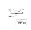
すなわち、本発明は、図1に示すように、未定着トナー像が担持された記録シート1の未定着トナー像に表面が接触し且つ加熱及び加圧することで定着させる定着装置に用いられる無端状の定着ベルト2であって、前記未定着トナー像と接する表面は、微小硬度が5以上30以下であり且つ光沢度Gs(20°)が50以上に設定されていることを特徴とするものである。
That is, as shown in FIG. 1, the present invention is an endless shape used in a fixing device that is fixed by heating and pressing the surface of the
このような技術的手段において、定着ベルト2の微小硬度が5未満では定着ベルト2表面が柔らか過ぎ、特にハーフトーン画像(トナー濃度の中間調部分)のような場合には、定着ニップ域で定着ベルト2がトナー像の凹凸に合った変形を行うようになり、トナー像表面を十分均一に加圧することができなくなり、光沢のある画像を得難くなる。一方、微小硬度が30を超えるようになると、定着ニップ域でトナー像を押しつぶすようになり、エッジボイドを発生したり、シャープな画像が得られないようになる。尚、微小硬度は、ダイナミック超微小硬度計DUH−201((株)島津製作所製)を用いて測定した値であり、薄い定着ベルト2の表面硬度を測定可能なものである。 In such a technical means, when the microhardness of the fixing belt 2 is less than 5, the surface of the fixing belt 2 is too soft. In particular, in the case of a halftone image (a halftone portion of toner density), fixing is performed in the fixing nip region. The belt 2 is deformed according to the unevenness of the toner image, and the surface of the toner image cannot be pressed sufficiently uniformly, making it difficult to obtain a glossy image. On the other hand, when the microhardness exceeds 30, the toner image is crushed in the fixing nip region, and edge voids are generated and a sharp image cannot be obtained. The micro hardness is a value measured using a dynamic ultra micro hardness meter DUH-201 (manufactured by Shimadzu Corporation), and can measure the surface hardness of the thin fixing belt 2.
また、定着ベルト2の微小硬度を所定の値に選定したとしても、定着ベルト2を使用する方式ではベルト表面がトナー像に写し取られるため、定着ベルト2の表面性が粗い場合には高光沢画像を得難いようになる。本発明では、定着ベルト2の鏡面光沢度としてより微小な凹凸を評価することが必要との判断から、入射角を20°とする光沢度Gs(20°)を規定した。そして、このGs(20°)が50以上に設定されることで、画像表面の光沢も高く、また、光沢度差を小さく維持できるようになる。仮に、Gs(20°)が50未満では、画像の光沢性が低下してしまい、特に写真プリントのような適用ができなくなる。 Even if the microhardness of the fixing belt 2 is selected to be a predetermined value, in the method using the fixing belt 2, the surface of the belt is copied to a toner image. It becomes difficult to obtain images. In the present invention, the glossiness Gs (20 °) with an incident angle of 20 ° is defined from the judgment that it is necessary to evaluate more minute unevenness as the specular glossiness of the fixing belt 2. When this Gs (20 °) is set to 50 or more, the gloss of the image surface is high and the difference in glossiness can be kept small. If Gs (20 °) is less than 50, the glossiness of the image is lowered, and in particular, it cannot be applied as a photographic print.
また、本発明では、定着ベルト2の微小硬度を6以上30以下にすることが好ましく、これによれば、定着ベルト2自体の耐摺擦性を一層高めることができるようになり、長期に亘って安定した画像を維持できるようになる。 In the present invention, it is preferable that the microhardness of the fixing belt 2 is 6 or more and 30 or less. According to this, the friction resistance of the fixing belt 2 itself can be further improved, and the fixing belt 2 can be used for a long time. And maintain a stable image.
更に、本発明の定着ベルト2は、耐熱性ベルト基材の表面に弾性層又は更に離型層が積層されたものとすることが好ましく、定着ベルト2としてベルト基材表面に弾性層を積層することで、定着ベルト2の機械的強度を向上させると共に安定した微小硬度を実現できるようになる。また、弾性層の上に更に離型層を備えることであっても差し支えなく、更には、ベルト基材の表面に離型層を備えるようにしてもよい。特に、離型層では定着ベルト2へのトナーの付着を抑止し、定着ベルト2表面の清浄作用を長期に亘って維持することができるようになる。
そして、弾性層及び離型層としては、フルオロカーボンシロキサンゴムを主成分とするものとすることが好ましく、これによれば、定着ベルト2へのトナー等の汚れ固着を抑止し、長期に亘って安定した表面を維持することができるようになる。更に、弾性層及び離型層としてフッ素微粒子を分散させたフルオロカーボンシロキサンゴムを主成分とするものにすれば、一層効果的になる。
Further, the fixing belt 2 of the present invention preferably has an elastic layer or further a release layer laminated on the surface of the heat-resistant belt base material, and an elastic layer is laminated on the surface of the belt base material as the fixing belt 2. As a result, the mechanical strength of the fixing belt 2 can be improved and a stable micro hardness can be realized. Further, a release layer may be further provided on the elastic layer, and further, a release layer may be provided on the surface of the belt base material. In particular, in the release layer, toner adhesion to the fixing belt 2 can be suppressed, and the cleaning action on the surface of the fixing belt 2 can be maintained over a long period of time.
The elastic layer and the release layer are preferably composed mainly of fluorocarbon siloxane rubber. According to this, the toner and the like are prevented from being adhered to the fixing belt 2 and stable for a long period of time. The surface can be maintained. Furthermore, it becomes more effective if the main component is a fluorocarbon siloxane rubber in which fluorine fine particles are dispersed as the elastic layer and the release layer.
また、本発明は、定着ベルト2のみならず、定着装置をも対象とするものであり、この場合、未定着トナー像が担持された記録シート1の未定着トナー像に定着ベルト2の表面が接触し且つ加熱加圧することで定着させる定着装置における定着ベルト2として、上述の定着ベルト2を用いるようにすればよい。
The present invention is intended not only for the fixing belt 2 but also for a fixing device. In this case, the surface of the fixing belt 2 is added to the unfixed toner image of the
更に、このような定着装置に好適な記録シート1としては、少なくともトナー像担持面側に熱可塑性樹脂層が設けられ、この熱可塑性樹脂層上にトナー像を定着させるようにすることが好ましく、これによれば、トナー像を熱可塑性樹脂層に埋め込むことができ、画像の光沢性が向上するようになる。更にまた、トナー像の最上層として透明トナーを使用するようにすれば、画像面全面に亘って透明トナーを形成することができ、画像の光沢度を更に向上させ、より写真画像に近い仕上がりを得ることができるようになる。
Further, as the
また、トナー像が熱可塑性樹脂層に有効に埋め込まれる観点から、定着ニップ内の熱可塑性樹脂層の溶融粘度は、110℃の条件下にて104Pa・s以下となるように設定されていることが好ましい。
そして、画像の光沢むらを低減する観点から、定着された後の記録シート1上のトナー像は、当該記録シート1内での異なる画像面積率での光沢度の差ΔGs(20°)が10以下に設定されることが好ましい。ここで、ΔGs(20°)とは、プロセスブラックの面積率を10%間隔で出力したときの夫々のGs(20°)を測定し、その最大値と最小値との差を意味する。
Further, from the viewpoint of effectively embedding the toner image in the thermoplastic resin layer, the melt viscosity of the thermoplastic resin layer in the fixing nip is set to be 10 4 Pa · s or less under the condition of 110 ° C. Preferably it is.
From the viewpoint of reducing uneven glossiness of the image, the toner image on the
更に、本発明は、画像形成装置をも対象とするものであり、この場合、記録シート1上に未定着トナー像を形成する作像エンジンと、上述の定着装置を備えるようにすればよい。また、このような画像形成装置のうち、作像エンジンが中間転写ベルトを用いる態様のものにおいては、定着ベルト2が中間転写ベルトを兼用するようにしてもよい。
Furthermore, the present invention is also intended for an image forming apparatus. In this case, the image forming engine for forming an unfixed toner image on the
本発明によれば、未定着トナー像が担持された記録シートの未定着トナー像に表面が接触し且つ加熱及び加圧することで定着させる定着装置に用いられる無端状の定着ベルトとして、定着ベルトの表面の微小硬度を5以上30以下とし且つ光沢度Gs(20°)を50以上に設定したので、長期に亘って安定した高光沢画像が得られるようになる。特に、ハーフトーン画像のような画像濃度が異なる場合でも、良好な平滑性並びに均一な光沢性を得ることができ、画像段差感や画像境界部に生じるエッジボイドのない画像を得ることができる。
また、このような定着ベルトを用いることで、良好な平滑性並びに均一な光沢性が長期に亘って形成可能な定着装置並びに画像形成装置を提供することができる。
According to the present invention, as an endless fixing belt used in a fixing device that fixes an unfixed toner image of a recording sheet carrying an unfixed toner image by contacting the surface and heating and pressurizing the fixing belt, Since the microhardness of the surface is set to 5 or more and 30 or less and the glossiness Gs (20 °) is set to 50 or more, a high-gloss image that is stable over a long period of time can be obtained. In particular, even when the image density is different, such as a halftone image, good smoothness and uniform gloss can be obtained, and an image free from an edge void generated at the image step feeling and the image boundary portion can be obtained.
Further, by using such a fixing belt, it is possible to provide a fixing device and an image forming apparatus capable of forming good smoothness and uniform gloss over a long period of time.
以下、添付図面に示す実施の形態に基づいて本発明を詳細に説明する。
◎実施の形態1
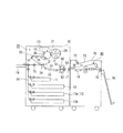
図2は、本発明が適用されたカラー画像形成装置の実施の形態1を示す。同図において、本実施の形態の画像形成装置は、例えば電子写真方式を採用したものであって、イエロー(Y色)、マゼンタ(M色)、シアン(C色)及びブラック(K色)の4色トナー像を形成する作像エンジン20と、作像エンジン20に記録材としての用紙を供給する多段の給紙カセット11〜13を引き出し可能に収容し、作像エンジン20の用紙搬送方向下流側に定着器40を配設したものとなっている。
Hereinafter, the present invention will be described in detail based on embodiments shown in the accompanying drawings.
FIG. 2 shows
本実施の形態の作像エンジン20は、所謂ロータリー方式であり、感光体ドラム21上に形成された各色トナー像を中間転写ベルト30上へ多重転写するようになっている。
感光体ドラム21の周囲には、感光体ドラム21を帯電する帯電ロール等の帯電器22、感光体ドラム21上に潜像を形成するレーザスキャナ等の露光器23、感光体ドラム21上の潜像を顕像化する現像器24、感光体ドラム21上の各色トナー像を中間転写ベルト30上に一次転写する例えば一次転写ロールからなる一次転写器25、感光体ドラム21上に残留した残留トナーを清掃する感光体クリーナー26が配設されている。
The
Around the
また、中間転写ベルト30は、複数の張架ロールに張架され、例えば張架ロール31を駆動ロール、張架ロール32をテンションロールとして循環搬送するものであり、例えば二次転写ロールからなる二次転写器34が張架ロール33をバックアップロールとして対向配置されている。更に、この中間転写ベルト30の張架ロール31と対向する位置には、中間転写ベルト30上の残留トナーを清掃するベルトクリーナー35が設けられている。
更に、作像エンジン20の上方には、現像器24に各色トナーを補給する4色のトナーボックス36が設けられ、図示外の搬送路を介して現像器24内の夫々の色に対応した位置にトナーを供給するようになっている。
The
Further, a four-
本実施の形態における用紙搬送系は、次のようになっている。夫々の給紙カセットから送り出された用紙は、用紙搬送経路14に搬送され、二次転写器34に入る前に用紙の位置決め規制を行うレジストロール15、二次転写器34によって未定着トナー像が転写された用紙を搬送する搬送ベルト16、未定着トナー像を定着する定着器40、定着後の用紙を排出トレイ18へ送り出す排出ロール17等が設けられている。そして、本実施の形態では、給紙カセット11〜13の他に用紙を手差し供給可能な手差しトレイ19が設けられ、用紙搬送経路14への用紙供給を可能にしている。
The paper transport system in the present embodiment is as follows. The sheets sent out from the respective sheet feeding cassettes are conveyed to the
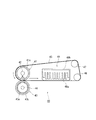
特に、本実施の形態の定着器40は図3のように構成されている。同図において、定着器40は、ハロゲンランプ等の加熱源42を内部に有する定着ロール41と、この定着ロール41に対向して配置され且つ内部に加熱源44を有する加圧ロール43と、定着ロール41と加圧ロール43との間に挟持搬送され、定着ロール41と複数のロール部材(剥離ロール46、ステアリングロール47)に張架されて循環する定着ベルト45と、定着ロール41の下流側で定着ベルト45裏面に接して定着ベルト45を冷却する冷却器48とを備えたものとなっている。
In particular, the fixing
定着ロール41は、熱伝導性の高いアルミニウムやステンレス等の金属製コア41aの周囲に厚さ10〜200μm程度のPFAチューブ等からなる離型層(図示せず)が形成された構成となっており、コア41aの内部に加熱源42が設けられ、この加熱源42は定着ロール41表面が所定の温度になるように加熱制御されている。
一方、加圧ロール43は、熱伝導性の高いアルミニウムやステンレス等の金属製のコア43aの周囲にゴム硬度(JIS−A硬度)30〜70度程度のシリコーンゴム等の弾性層43bが1〜3mm程度に均一に被覆されており、弾性層43bの表面には定着ロール41の離型層と同様の離型層(図示せず)が形成されている。また、本実施の形態では、この加圧ロール43のコア43aの内部にも加熱源44が設けられ、加圧ロール43の表面が定着ロール41の表面と同程度か0〜30℃程度低い所定の温度になるように加熱制御されている。
そのため、定着器40に搬送された用紙は、定着ロール41と加圧ロール43との定着ニップ域Nにて、トナー像面が定着ベルト45に接した状態で十分な加熱、加圧がなされるようになる。尚、加圧ロール43は、図示外の支持フレームに支持され、用紙が定着ニップ域Nを通過する際、定着ロール41と加圧ロール43との間に所定の荷重を印加するための加圧機構が設けられており、用紙の有無に合わせて加圧ロール43がリトラクトするようになっている。
The fixing
On the other hand, the
Therefore, the sheet conveyed to the fixing
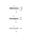
そして、定着ベルト45は、図4(a)に示すように、耐熱性を有する基材層45aの上に、弾性層45b、離型層45cを備えた3層構造のものとなっている。
基材層45aとしては、耐熱性、機械的強度及び熱特性(熱伝導性や膨張係数等)などの観点から、PET、PBT、ポリイミド、ポリアミド、ポリアミドイミド、ポリベンズイミダゾール、サーモトロピック液晶ポリマー等の耐熱性樹脂シートや、ニッケル、アルミニウム、ステンレス等の金属シートを用いることが可能であるが、熱特性を考慮するとポリイミド、ポリベンズイミダゾールからなる耐熱性樹脂シートが好ましい。また、基材層45aとしては、帯電特性を考慮して、上述の耐熱性樹脂に導電性粉体やカーボンブラック等を添加して体積抵抗率を調整するようにしてもよく、その形成方法についても公知の方法であれば特に制限されるものではない。
As shown in FIG. 4A, the fixing
As the
更に、基材層45aの厚みは、定着ベルト45としての機械的強度、熱容量、熱伝導性等の観点から20〜200μmの範囲であることが望ましい。厚みが20μm未満であれば、機械的強度が不足して、定着ベルト45としての取扱性が悪くなり、また、厚みが200μmを超えるようになると定着ベルト45自体の熱容量が大きくなり過ぎ、ウォームアップ時間を長くしなければならなくなったり、それによる消費電力の増大も生じるようになる。
Furthermore, the thickness of the
また、弾性層45bとしては、耐熱性を有するものであれば特に限定されず、代表的にはシリコーンゴムやフッ素ゴムあるいはそれらのハイブリッドゴムが適用され、また、弾性層45bを形成する方法については公知の方法であれば特に制限されるものではない。
更に、弾性層45bの厚みとしては、弾性層45bとしての機械的強度、熱容量、熱伝導性の機能の観点からすれば、10〜200μmの範囲であることが好ましく、厚みが10μm未満の場合には弾性体としての機能が発揮されないばかりか、定着ニップ域Nにおける弾性変形や応力による歪によってゴム弾性が失われたり、破損が生じたりするようになる。一方、200μmを超えると弾性層45b自体の熱容量が大きくなり過ぎ、ウォームアップ時間を長くしなければならなくなったり、それによる消費電力が増大するようにもなる。
The
Furthermore, the thickness of the
離型層45cとしては、トナーに対する離型性を有する材料であれば特に制約されるものではなく、公知の材料を利用することが可能である。例えば、トナー像との離型性や耐熱性を考慮したものとしてPFA(四フッ化エチレン・パーフルオロアルコキシエチレン共重合体樹脂)やFEP(四フッ化エチレン・六フッ化プロピレン共重合体樹脂)、PTFE(四フッ化エチレン樹脂)が挙げられる。
更に、離型層45cとしてフッ素粒子が分散されたフルオロカーボンシロキサンゴムを主成分としたものを用いるようにすれば、離型層45c表面の安定性が長期に亘って確保されるようになり、光沢の高い画像が得られるようにもなる。
上述した離型層45cでは、各種添加剤の配合比や分子量を制御することによって、最適な硬度を選択することができ、また、離型層45cを形成する方法については、公知の方法であれば特に制限されるものではない。
そして、離型層45cの厚みとしては、離型層45cの摩耗による減耗やトナーとの離型性機能の観点から3〜50μm程度のものが好ましい。
The
Furthermore, if the
In the
The thickness of the
また、本実施の形態の定着ベルト45としては、上述したような構造の如何に関わらず、用紙のトナー像と接するベルト表面の微小硬度が5〜30であり、かつ、光沢度Gs(20°)が50以上に設定されている。そして、より好ましくは、微小硬度を6〜30とすることで、定着ベルト45の耐摺擦性を向上させることができるようになる。
微小硬度(DH:Dynamic Hardness)は、ダイナミック超微小硬度計DUH−201((株)島津製作所製)を用いて、測定荷重P(圧子が押し込み深さDに達した際の荷重)を測定すると共に、その際の測定荷重Pと押し込み深さDに基づき以下のように求めたものである。すなわち、硬度計の圧子の先端をベルト表面に垂直に一定速度で押し込み、そのときの押し込み深さDと必要な荷重Pを測定する。このため測定試料の弾性変形だけでなく塑性変形をも含んだ状態での特性が測定されるようになる。
Further, the fixing
The micro hardness (DH: Dynamic Hardness) is measured using a dynamic micro hardness tester DUH-201 (manufactured by Shimadzu Corporation), and the measurement load P (the load when the indenter reaches the indentation depth D) is measured. In addition, based on the measured load P and the indentation depth D at that time, the following is obtained. That is, the tip of the indenter of the hardness meter is pushed perpendicularly to the belt surface at a constant speed, and the pushing depth D and the necessary load P at that time are measured. For this reason, the characteristic in a state including not only elastic deformation but also plastic deformation of the measurement sample comes to be measured.
測定条件としては、次のようになっている。
・圧子:三角錐(115°)、ベルコビッチタイプ
・負荷速度:0.14219mN/sec
・試験荷重:3mN
・測定環境:22℃55%RH
・算出式:微小硬度(DH)=α×P/D2(ここで、α=3.8584)
The measurement conditions are as follows.
・ Indenter: Triangular pyramid (115 °), Belkovic type ・ Load speed: 0.14219 mN / sec
・ Test load: 3mN
・ Measurement environment: 22 ℃ 55% RH
Calculation formula: micro hardness (DH) = α × P / D 2 (where α = 3.8854)
更に、光沢度Gs(20°)は、JIS Z8741に基づいてグロス測定器GB−4512(BYK−Gardner社製)を用いて、入射角と反射角を20°としたときに得られる数値であり、本実施の形態では、定着ベルト45表面の光沢度が50以上となるようになっている。
Further, the glossiness Gs (20 °) is a numerical value obtained when an incident angle and a reflection angle are set to 20 ° using a gloss measuring device GB-4512 (manufactured by BYK-Gardner) based on JIS Z8741. In this embodiment, the glossiness of the surface of the fixing
尚、本実施の形態における定着ベルト45は、上述した3層構成のものに限らず、例えば、図4(b)(c)に示すような構成のものであっても使用可能である。すなわち、図4(b)に示すように、基材層45a上に離型層45cのみ備える構成や、(c)に示すように、基材層45aのみの構成であってもよく、この場合、いずれも微小硬度及び光沢度Gs(20°)を満足するようにすればよい。
Note that the fixing
そして、このような光沢を得るための方法としては特に制約されるものではないが、上述のベルトの層構成に応じて適宜選択する必要があると言える。例えば、基材層45aの上層に離型層45cを有するベルトの場合、離型層45cの塗布工程や、一次加硫時のパラメータを適宜選択して得られる。また基材層45aのみで形成されたベルトを用いる場合においては、例えば、研磨テープ等によりその表面を湿式又は乾式で研磨する方法により行うものであり、特に研磨テープの5000番以上のものを選ぶなど適宜研磨条件を選択することが重要である。
A method for obtaining such glossiness is not particularly limited, but it can be said that it is necessary to select appropriately according to the layer configuration of the belt described above. For example, in the case of a belt having a
また、図3に示すように、本実施の形態における定着器40に用いられる剥離ロール46は、定着ベルト45の移動に従動して回転し、この剥離ロール46が定着ベルト45を巻き付けながら張架することで、定着ベルト45の移動方向を急激に変化させるようになり、定着ベルト45上の用紙は剥離ロール46の位置で用紙自体の剛性によって自然に定着ベルト45から剥離されるようになる。また、ステアリングロール47は、定着ベルト45自体を常時緊張させるようにしたものであり、定着ベルト45を外方に押圧することで緊張を維持させ、定着ベルト45が循環移動したときに生じる偏りを修正するために設けられている。
As shown in FIG. 3, the peeling
更に、本実施の形態での冷却器48は、定着ロール41と剥離ロール46との間で、定着ベルト45裏面に接して設けられ、定着ベルト45の熱を吸熱することで定着ベルト45を冷却するようになっている。そのため、定着ベルト45に密着搬送される用紙の冷却が行われるようになる。本実施の形態での冷却器48は、定着ベルト45に沿った面から略直交する方向に延びた多数の放熱フィンが設けられたフィン部材48aと、これを覆うように設けられたカバー48bとで筒状に構成されたものであり、図示外の送風ブロアによって内部に空気を流すことでフィン部材48aの熱を強制的に放熱させるようにしたものである。
Further, the cooler 48 in the present embodiment is provided between the fixing
ここで、本実施の形態において用いられる用紙について説明する。
本実施の形態の画像形成装置によれば、通常の画像形成装置で用いられる各種用紙(例えば普通紙、コート紙、アート紙等)に適用可能であるが、特に、図5に示すような構成の用紙を使用することで最も有効な効果が得られるようになる。
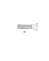
図5において、用紙は、所謂普通紙と同様の成分(セルロース等)からなる基材層L1と、基材層L1の両面に被覆される防湿層L2、更に、防湿層L2の上に被覆される受像層L3とで構成されている。
Here, the paper used in the present embodiment will be described.
The image forming apparatus according to the present embodiment can be applied to various types of paper (for example, plain paper, coated paper, art paper, etc.) used in a normal image forming apparatus. In particular, the configuration shown in FIG. The most effective effect can be obtained by using this paper.
In FIG. 5, the paper is coated on a base material layer L1 made of the same component as that of so-called plain paper (cellulose or the like), a moisture-proof layer L2 coated on both surfaces of the base material layer L1, and further on the moisture-proof layer L2. Image receiving layer L3.
基材層L1として、特に、写真画像のような高光沢画像を形成する場合には、白色度が高く、適度な厚み(150〜230μm)を有していることが望ましい。
また、防湿層L2としては、例えばポリエチレン等の透気性の低い樹脂からなり、数μm程度のものでよい。この防湿層L2によって基材層L1への水分の侵入が抑止され、高湿環境下にあっても基材層L1が水分を吸ってカールするのを防いでいる。
更に、受像層L3としては、例えばポリエステル等の熱可塑性樹脂を主成分とする層であり、トナー像が形成される面(記録面)に形成されている。受像層L3の厚さとしては5〜30μm程度が好ましく、受像層L3の厚さがこの範囲を下回ると、定着時にトナーを受像層L3内に十分埋め込むことができなくなり、画像表面に凹凸を生じて光沢度が低下する一方、この範囲を上回ると、例えば剥離部位(剥離ロールによる)などで用紙が湾曲したときに画像表面にクラックが発生し易くなる。尚、受像層L3としては、ポリエステルに限らず、スチレン−(メタ)アクリル共重合体、スチレン−ブタジエン共重合体、エポキシ樹脂、ポリウレタン等の合成樹脂を用いることができる。
As the base material layer L1, in particular, when a high gloss image such as a photographic image is formed, it is desirable that the white layer has a high whiteness and an appropriate thickness (150 to 230 μm).
Further, the moisture-proof layer L2 is made of a resin having low air permeability such as polyethylene and may be about several μm. The moisture-proof layer L2 prevents moisture from entering the base material layer L1, and prevents the base material layer L1 from absorbing and curling even in a high humidity environment.
Further, the image receiving layer L3 is a layer mainly composed of a thermoplastic resin such as polyester, and is formed on a surface (recording surface) on which a toner image is formed. The thickness of the image receiving layer L3 is preferably about 5 to 30 μm. If the thickness of the image receiving layer L3 is less than this range, the toner cannot be sufficiently embedded in the image receiving layer L3 at the time of fixing, resulting in unevenness on the image surface. On the other hand, when the glossiness is lowered, exceeding this range, cracks are likely to occur on the image surface when the paper is curved at the peeling site (by the peeling roll), for example. The image-receiving layer L3 is not limited to polyester, and synthetic resins such as styrene- (meth) acrylic copolymer, styrene-butadiene copolymer, epoxy resin, and polyurethane can be used.
次に、本実施の形態における画像形成装置の作動について、特に定着器40での作動を中心に説明する。
図6(a)(b)は、定着時の定着ニップ域Nでのトナー像の埋め込み状況を示すもので、(a)は定着前の定着ベルト45と未定着トナー像が転写された用紙とが接触開始した状態を示し、(b)は定着完了後の状態を示すものとなっている。尚、この例では、定着ベルト45は基材層45a上に離型層45cを被覆したものとして示している。
Next, the operation of the image forming apparatus in the present embodiment will be described focusing on the operation of the fixing
FIGS. 6A and 6B show the embedding state of the toner image in the fixing nip area N at the time of fixing. FIG. 6A shows the fixing
本実施の形態では、定着前に(a)のような状態であったものが、定着ニップ域Nでは用紙の受像層L3(熱可塑性樹脂層)中にトナー像が押し込まれるようになる。そして、特に本実施の形態では、定着ベルト45の微小硬度及び光沢度Gs(20°)を所望の値にしていることから、定着ニップ域Nでのトナー像への十分均一な加圧が可能であり、未定着トナー像が用紙の受像層L3中に埋め込まれるようになる。
In the present embodiment, the toner image is pushed into the image receiving layer L3 (thermoplastic resin layer) of the paper in the fixing nip area N, although the state as shown in FIG. In particular, in this embodiment, since the microhardness and glossiness Gs (20 °) of the fixing
また、図7(a)(b)は、画像濃度が異なる場合の定着時の定着ニップ域Nでのトナー像の埋め込み状況を示すもので、(a)は定着前に定着ベルト45と未定着トナー像が接触する直前の状態であり、(b)は定着ニップ域Nでの加圧状態を示している。
ここで、未定着トナー像は、(c)のように、画像濃度が異なっており、ベタ部T100(100%)、10%濃度部(T10)、50%濃度部(T50)の3種の場合を例示しているが、T100ではトナーが一番厚く、続いてT50、T10の順に薄くなっている。
そのため、定着ベルト45で押圧された場合、定着ベルト45の硬さが柔らか過ぎるとトナーの厚さが変化したとき、ベルト表面もそれに追随して変化し、夫々のトナー(T100、T10、T50)に均等な加圧がなされず、例えばT100では用紙の受像層L3への埋め込み不足を生じるようになり、定着後の画像表面の光沢性が低下するようになる。一方、定着ベルトの硬さが硬すぎると、一番厚いT100に大きな加圧がなされ、画像崩れを生じたり、夫々のトナー(T100、T10、T50)を十分均一に受像層L3に埋め込むことができずに、却って光沢むらを生じるようにもなる。
FIGS. 7A and 7B show the embedding state of the toner image in the fixing nip area N at the time of fixing when the image density is different. FIG. 7A shows that the fixing
Here, as shown in (c), the unfixed toner image has different image densities, and has three types of solid part T100 (100%), 10% density part (T10), and 50% density part (T50). Although the case is illustrated, the toner is the thickest at T100, and then becomes thinner in the order of T50 and T10.
Therefore, when pressed by the fixing
本実施の形態では、定着ベルト45の微小硬度及び表面の光沢度Gs(20°)を所望の値に調整したので、特に、上述のような画像濃度が異なる画像であっても、定着時の均一な加圧を可能にし、更に、定着後の画像表面の平滑性も向上できることから、写真画像のような高光沢画像を実現することができるようになる。
In the present embodiment, the microhardness and surface glossiness Gs (20 °) of the fixing
本実施の形態では、フルカラー4色の画像形成について説明したが、例えば透明トナーを加えた5色の画像形成装置にも適用でき、この場合、トナー像の最上層を透明トナーとすることで、この透明トナーを画像全域に亘って形成するようにすれば、カラートナーが形成されない部位(用紙自体の表面)の光沢度も向上させることができるようになる。また、全面に亘って、透明トナーによって平均化するようにすることも可能になり、一層画像の光沢度を向上させることができるようになる。 In the present embodiment, full-color four-color image formation has been described. However, the present invention can also be applied to, for example, a five-color image forming apparatus to which transparent toner is added. In this case, by using the uppermost layer of the toner image as a transparent toner, If this transparent toner is formed over the entire area of the image, the glossiness of the portion where the color toner is not formed (the surface of the paper itself) can be improved. In addition, the entire surface can be averaged with the transparent toner, and the glossiness of the image can be further improved.
更に、本実施の形態では、所謂ロータリー方式の画像形成装置を示したが、例えば各色毎の作像ユニットを中間転写ベルトに対向して並列配置させた、所謂タンデム方式においても同様の定着器を備えるようにすれば、写真画像のような高光沢画像が得られるようになる。
更にまた、定着器として、定着ベルトを用いた定着器以外に、例えばその上流側に通常の加熱加圧方式の定着器を追加配置して、通常の普通紙へ出力する低光沢プリントと、写真画像のような高光沢プリントとを定着器を切り替えて行うようにしてもよい。
Furthermore, in the present embodiment, a so-called rotary type image forming apparatus is shown. However, for example, a similar fixing device is also used in a so-called tandem type in which image forming units for each color are arranged in parallel facing an intermediate transfer belt. If provided, a high gloss image such as a photographic image can be obtained.
Furthermore, in addition to the fixing device using a fixing belt as a fixing device, for example, a normal heating / pressing type fixing device is additionally arranged on the upstream side of the fixing device, and a low-gloss print that outputs to normal plain paper, and a photograph A high gloss print such as an image may be performed by switching the fixing device.
◎実施の形態2
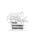
図8は、本発明が適用された画像形成装置の実施の形態2を示すものである。本実施の形態は、実施の形態1と略同様に構成されるが、定着器40を画像形成ユニット10に装着自在なオプションユニット60側に配置した構成となっている。そのため、画像形成ユニット10側には、用紙の搬送経路中に通常の加熱加圧方式の定着部50が実装されている。尚、実施の形態1と同様の構成要素には同様の符号を付し、ここではその詳細な説明は省略する。
Embodiment 2
FIG. 8 shows Embodiment 2 of the image forming apparatus to which the present invention is applied. Although the present embodiment is configured in substantially the same manner as the first embodiment, the fixing
本実施の形態における定着部50は、通常の構成であり、加熱ロール51と加圧ロール52とのニップによって定着が行われるようになっている。尚、本実施の形態では、加熱ロール51及び加圧ロール52共に内部にハロゲンランプ等の加熱源を備えている。
そのため、本実施の形態では、画像形成ユニット10内に備わる定着部50によって用紙上の未定着トナー像は一旦定着が施された後、更にオプションユニット60の定着器40によって高光沢な画像が得られるようになる。そして、この定着器40によって高光沢画像がなされた用紙は、オプションユニット60側の排出ロール61から排出トレイ18へ排出されるようになる。尚、図中、符号53は定着部50の直後に設けられた搬送ロールである。
The fixing
Therefore, in the present embodiment, the unfixed toner image on the paper is once fixed by the fixing
このような構成において、定着器40は実施の形態1と同様のため、本実施の形態においても実施の形態1と同様の効果を奏する。
In such a configuration, since the fixing
◎実施の形態3
図9は、本発明が適用された画像形成装置の実施の形態3を示すものである。本実施の形態は、実施の形態2と略同様に構成されるが、画像形成ユニット10に装着自在なオプションユニット70の構成が実施の形態2の構成と異なる。また、画像形成ユニット10内には、給紙カセットを4個(符号11,12,13a,13b)備え、作像エンジン20の上部にはトナーボックスを備えていない。尚、実施の形態2と同様の構成要素には同様の符号を付し、ここではその詳細な説明は省略する。
FIG. 9 shows
本実施の形態におけるオプションユニット70は、画像形成ユニット10内の定着部50にて一旦定着され、排出ロール17から排出される用紙に対し、切替部材71によって下流側の用紙搬送経路を切り替えるようになっている。すなわち、オプションユニット70の第1排出ロール72からオプションユニット70の上部筐体で形成される第1排出トレイ73へ排出する経路と、搬送ベルト74を介して実施の形態1と同様の定着器40へ導き、定着後に第2排出ロール75から第2排出トレイ76へ導く経路とに切り替えられる。
The
そのため、例えば、普通紙に文字ものをプリントしたときには、定着部50にて定着が行われた画像をそのまま第1排出トレイ73へ排出する低光沢プリントを実現し、一方、専用用紙に写真画像をプリントするときには、定着部50で一旦仮定着を行った後、定着器40によって高光沢画像として第2排出トレイ76へ排出する高光沢プリントを実現できるようになる。
本実施の形態では、このように、画像に合わせた定着を選択することができ、その分、画像に合った視認性を確保することができるようになり、また、消費電力も低減させることが可能になる。
Therefore, for example, when text is printed on plain paper, low-gloss print is realized in which the image fixed by the fixing
In this embodiment, fixing according to the image can be selected as described above, and accordingly, visibility matching the image can be secured, and power consumption can be reduced. It becomes possible.
更に、本実施の形態においても、定着器40を実施の形態1と同様に構成したことから、高光沢画像を実現することができるようになる。
Further, in the present embodiment, since the fixing
◎実施の形態4
図10は、本発明が適用された画像形成装置の実施の形態4を示すものである。本実施の形態は、実施の形態1と略同様に構成されるが、定着器40が専用とはならず、定着器40の定着ベルトが作像エンジン20の中間転写ベルトを兼用するベルト部材80となっている。尚、実施の形態1と同様の構成要素には同様の符号を付し、ここではその詳細な説明は省略する。
Embodiment 4
FIG. 10 shows Embodiment 4 of an image forming apparatus to which the present invention is applied. Although the present embodiment is configured in substantially the same manner as the first embodiment, the fixing
本実施の形態では、作像エンジン20の中間転写ベルトと定着ベルトとが共通化された1本のベルト部材80となっており、このベルト部材80は、複数の張架ロール(例えば、駆動ロール82、定着ロール41、剥離ロール46、ステアリングロール47等)に掛け渡されて循環移動するようになっている。尚、符号81は二次転写器34と対向配置されるバックアップロールであり、符号83は、二次転写後の用紙を搬送する搬送ベルトとなっている。
In this embodiment, the intermediate transfer belt and the fixing belt of the
本実施の形態においては、ベルト部材80上に4色のトナー像を形成するまで、二次転写器34、加圧ロール43はリトラクトしており、また、定着ロール41の加熱源はベルト部材80を搬送されるトナー像に影響のない範囲に温度が低下している。このような状況下で4色のトナー像がベルト部材80上に多重転写された後、二次転写器34とバックアップロール81との間の転写バイアスによってベルト部材80上の多重化トナー像は用紙に一括転写される。一括転写された用紙は、搬送ベルトを介して定着ロール41と加圧ロール43で形成される定着ニップ域にて定着がなされるようになる。
In the present embodiment, the
本実施の形態では、このような転写同時定着方式の画像形成装置であり、このような方式にあってもベルト部材80が実施の形態1と同様の構成となっていることから、実施の形態1と同様の効果を奏する。
尚、本実施の形態では、所謂ロータリー方式の画像形成装置としたが、所謂タンデム方式を採用すれば、二次転写器34や加圧ロール43のリトラクトを不要とし、更に、加熱源の制御も簡略化されることは明らかである。
The present embodiment is an image forming apparatus of such a simultaneous transfer and fixing system, and the
In the present embodiment, a so-called rotary type image forming apparatus is used. However, if a so-called tandem type is adopted, the retracting of the
本実施例は、各種の定着ベルトによる画像評価テストを行ったものである。
評価した定着ベルトは、ベルト基材として周長527.8mm×幅330mm×厚さ75μmの無端状で、カーボンブラックを添加して体積抵抗率をRv=1012Ω・cmに調整したポリイミド基材を使用した。
In this embodiment, image evaluation tests using various fixing belts are performed.
The evaluated fixing belt is a polyimide base material having an endless shape with a peripheral length of 527.8 mm, a width of 330 mm, and a thickness of 75 μm as a belt base material, and having a volume resistivity adjusted to Rv = 10 12 Ω · cm by adding carbon black. It was used.
このベルト基材の上に次の処理を行い試料とした。
○実施例1
基材上に、弾性層としてフルオロカーボンシロキサンゴム前駆体組成物であるSIFEL610(信越化学工業(株)製)と、更に、離型層として硬度を変えるために異なる種類のフッ素微粒子であるPTFEとをフッ素系溶媒に分散させて調整した塗布液を浸漬塗布することで厚さが略30〜50μmの塗膜を形成した。その後一次加硫、二次加硫過程を経て、最終的に微小硬度が3〜35である表面層が形成された7種の定着ベルトを得た。浸漬塗布法によって得られたベルト表面の光沢度Gs(20°)は一次加硫パラメータを制御することでいずれも50以上のものを得た。
そして、この中から、微小硬度が3及び35の2種のものを比較例1及び比較例3とした。
○比較例1
上述したように、実施例1の中から、微小硬度の小さいものを選定した。
○比較例2
基材上に、弾性層としてフルオロカーボンシロキサンゴム前駆体組成物であるSIFEL610(信越化学工業(株)製)と、更に、離型層としてフッ素微粒子であるPTFEとをフッ素系溶媒に分散させて調整した塗布液を浸漬塗布することで塗膜を形成した。その後一次加硫、二次加硫過程を経て、最終的に表面層膜厚が略30μmとなる表面層を形成したベルトを作成した。このときベルト表面グロスは、一次加硫パラメータを制御することでいずれも50以上のものを得たが、更にこの後、1μm程度の微小粒子を用いてベルト表面をドライ方式のホーニング処理(梨地ブラスト処理)し、ベルト表面の光沢度Gs(20°)を50以下としたベルトを得た。
○比較例3
上述したように、実施例1の中から、微小硬度の大きいものを選定した。
○比較例4
基材上に処理を行わず、基材単体のみを用いて厚さ80μmの1層構造のベルトを得た。また、このとき、微小硬度は45であり、ベルトの光沢度Gs(20°)は90以上であった。
The following treatment was performed on this belt base material to prepare a sample.
○ Example 1
On the base material, SIFEL610 (manufactured by Shin-Etsu Chemical Co., Ltd.) which is a fluorocarbon siloxane rubber precursor composition as an elastic layer, and PTFE which is a different kind of fluorine fine particles for changing hardness as a release layer. A coating film having a thickness of approximately 30 to 50 μm was formed by dip coating a coating solution prepared by dispersing in a fluorine-based solvent. Thereafter, through the primary vulcanization process and the secondary vulcanization process, finally, seven types of fixing belts on which a surface layer having a microhardness of 3 to 35 was formed were obtained. The belt surface glossiness Gs (20 °) obtained by the dip coating method was 50 or more by controlling the primary vulcanization parameters.
Of these, two samples having a microhardness of 3 and 35 were designated as Comparative Example 1 and Comparative Example 3.
○ Comparative Example 1
As described above, one with a small micro hardness was selected from Example 1.
○ Comparative Example 2
SIFEL610 (manufactured by Shin-Etsu Chemical Co., Ltd.) which is a fluorocarbonsiloxane rubber precursor composition as an elastic layer and PTFE which is a fluorine fine particle as a release layer are dispersed in a fluorine-based solvent as an elastic layer. A coating film was formed by dip coating the applied coating solution. Thereafter, a belt having a surface layer having a surface layer thickness of approximately 30 μm was formed through a primary vulcanization process and a secondary vulcanization process. At this time, the belt surface gloss of 50 or more was obtained by controlling the primary vulcanization parameters. After this, the belt surface was further subjected to a dry honing treatment (pear blasting using fine particles of about 1 μm). The belt surface glossiness Gs (20 °) was 50 or less to obtain a belt.
○ Comparative Example 3
As described above, one having a high microhardness was selected from Example 1.
○ Comparative Example 4
A single-layer belt having a thickness of 80 μm was obtained using only the base material without performing any treatment on the base material. At this time, the micro hardness was 45, and the glossiness Gs (20 °) of the belt was 90 or more.
この評価に用いた用紙及びトナーは次の通り。
用紙は、A4判(210×297mm)サイズで、基材層の両面にポリエチレン樹脂を約10μmの厚さにコーティングしたものに対し、画像面のみに、更にポリエステル樹脂を約20μmの厚さで塗工したものとした。
また、トナーは、ワックス成分が添加されたスチレン−アクリル樹脂からなる平均粒径5.6μmからなるものを使用した。
The paper and toner used for this evaluation are as follows.
The paper is A4 size (210 x 297 mm) size, and both sides of the base material layer are coated with polyethylene resin to a thickness of about 10 μm. On the image side only, polyester resin is further applied with a thickness of about 20 μm. It was what was crafted.
Further, a toner having an average particle size of 5.6 μm made of styrene-acrylic resin to which a wax component was added was used.
評価方法については、以下のように行った。
先ず、用紙に未定着トナー像を担持させるため、定着部を取り外したカラー画像形成装置DocuColor1256GA改造機(富士ゼロックス(株)製)を用いて、用紙上にトナー像を形成した。その後、この未定着トナー像を実施の形態1の定着器構成で、定着ベルトとして各種変更したものを挿通させて加熱加圧を行い、未定着トナー像が定着された画像の画像評価を行った。
About the evaluation method, it carried out as follows.
First, in order to carry an unfixed toner image on a sheet, a toner image was formed on the sheet using a color image forming apparatus DocuColor 1256GA remodeling machine (Fuji Xerox Co., Ltd.) with the fixing unit removed. After that, the unfixed toner image was subjected to heat and pressure by inserting various modified fixing belts with the configuration of the fixing device of the first embodiment, and an image evaluation of the image on which the unfixed toner image was fixed was performed. .
評価項目は、次の項目とした。
●画像の光沢度Gs
評価に用いた画像は、イエロー、シアン、マゼンタの3色を重畳させて得られるプロセスブラックの面積率を10%間隔で0〜100%まで変化させたトナー像を、夫々9×9mm以上の画像領域を有する矩形のパッチ画像として形成し、定着後の画像の光沢度Gs(20°)を測定した。そして、平均値(Ave)と最大値と最小値との差ΔGs(20°)を算出した。
このとき、ΔGs(20°)の数値が小さいほど画像平滑性に優れ、数値が大きいほど平滑性に欠けることとなる。
●エッジボイド
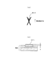
トナーの埋め込み性を確認する目的で、図11(a)に示すプロセスブラック100%のクロスラインチャート(×印)を用いて、用紙の熱可塑性樹脂層の溶融粘度を変えて画像のエッジボイドの発生状況(特に×印の上流側に発生する)をG0(エッジボイドなし)〜G5(エッジボイドが全体にある)の6段階に分けて評価した。尚、用紙の熱可塑性樹脂層の溶融粘度は、定着温度を変えることで行い、粘度が約103Pa・sと約104Pa・sでのエッジボイドを確認した。
●パッチ段差
パッチ画像の段差についても評価を行い、1辺が15mm角のプロセスブラック100%の画像を形成し、図11(b)に示すように、用紙表面とパッチ画像との段差hについて目視確認を行った。
そのときの結果を次の基準で評価した。
○:違和感なし、△:少し違和感あり、×:違和感が大きい
●平滑性
所定の写真チャートを出力し、画像の平滑性に対し、目視評価を行った。
そのときの結果を次の基準で評価した。
○:違和感なし、△:少し違和感あり、×:違和感が大きい
●ベルト弾性層の劣化
用紙の走行テスト(100,000枚)を行い、ベルト弾性層の劣化状態に対して目視評価を行った。
そのときの結果を次の基準で評価した。
○:ヒビ割れ発生はなし、△:軽微なヒビ割れが発生、×:顕著なヒビ割れが発生
The evaluation items were as follows.
● Glossiness Gs of image
The images used for the evaluation are toner images in which the area ratio of process black obtained by superimposing three colors of yellow, cyan, and magenta is changed from 0 to 100% at 10% intervals. A rectangular patch image having a region was formed, and the glossiness Gs (20 °) of the image after fixing was measured. Then, a difference ΔGs (20 °) between the average value (Ave), the maximum value, and the minimum value was calculated.
At this time, the smaller the numerical value of ΔGs (20 °), the better the image smoothness, and the larger the numerical value, the less smooth.
Edge void For the purpose of confirming the embedding property of the toner, the edge void of the image is changed by changing the melt viscosity of the thermoplastic resin layer of the paper by using a cross line chart (× mark) of 100% process black shown in FIG. The occurrence state (particularly generated on the upstream side of the x mark) was evaluated by dividing it into six stages from G0 (no edge voids) to G5 (the entire edge voids). The melt viscosity of the thermoplastic resin layer of the paper was changed by changing the fixing temperature, and edge voids were confirmed at viscosities of about 10 3 Pa · s and about 10 4 Pa · s.
● Patch step The step of the patch image is also evaluated, and an image of 100% process black with a side of 15 mm square is formed. As shown in FIG. 11B, the step h between the paper surface and the patch image is visually observed. Confirmed.
The results at that time were evaluated according to the following criteria.
○: No sense of incongruity, Δ: Some sense of incongruity, ×: Great sense of incongruity ● Smoothness A predetermined photographic chart was output, and the smoothness of the image was visually evaluated.
The results at that time were evaluated according to the following criteria.
○: No sense of incongruity, Δ: Some sense of incongruity, ×: Great sense of incongruity ● Deterioration of belt elastic layer A paper running test (100,000 sheets) was performed, and the deterioration state of the belt elastic layer was visually evaluated.
The results at that time were evaluated according to the following criteria.
○: No cracking occurred, △: Minor cracking occurred, ×: Significant cracking occurred
評価結果を図12に示す。
これによると、実施例1−1から1−5のように、微小硬度が5〜30であり、光沢度Gs(20°)が50以上であれば画像の光沢度Gsも80以上が確保され、光沢度差ΔGsも10以下と良好な画像が得られ、表面性の違和感もなかった。更に、パッチ段差もなくエッジボイドの発生もないため、平滑性に優れた画像を得ることができた。更にまた、定着ニップ内における用紙の熱可塑性樹脂における溶融粘度が104Pa・s以下となる定着条件においてもエッジボイドなどの画像欠陥を生ずることがなかった。
一方、微小硬度が3と小さい場合(比較例1)や35と大きい場合(比較例3)には、定着ベルトの光沢度Gs(20°)が50以上であっても、光沢度差ΔGsが若干大きくなり、熱可塑性樹脂の溶融粘度が104Pa・sのときに若干エッジボイドが発生したり、パッチ段差や平滑性の点で違和感を生じた。
また、実施例1と同様に作製し、表面を故意に粗くした場合(比較例2)では、表面粗さを反映して画像の光沢度が大きく低下したり、平滑性で大きな違和感が生じた。そして、この場合は、ベルトの表面にとりわけ画像エッジ部に相当する箇所のトナーが付着していることも確認された。
更に、微小硬度を45と大きくし、光沢度Gs(20°)を大幅に上げた場合(比較例4)では、画像の光沢度Gsや光沢度差ΔGsが低下すると共に、パッチ段差や平滑性で大きな違和感を生じた(光沢むらやエッジボイドが大)。特に、この場合、光沢度に関しては均一であるものの、用紙上の画像全体での画像グロスが低下し、高光沢画像の風合いが損なわれる結果となった。
この結果から、本件発明の有効性が確認された。
The evaluation results are shown in FIG.
According to this, as in Examples 1-1 to 1-5, if the microhardness is 5 to 30 and the glossiness Gs (20 °) is 50 or more, the glossiness Gs of the image is also secured to 80 or more. Further, the gloss difference ΔGs was 10 or less, and a good image was obtained, and the surface property was not uncomfortable. Furthermore, since there was no patch level difference and no edge voids, an image having excellent smoothness could be obtained. Furthermore, image defects such as edge voids did not occur even under fixing conditions in which the melt viscosity of the thermoplastic resin of the paper in the fixing nip was 10 4 Pa · s or less.
On the other hand, when the microhardness is as small as 3 (Comparative Example 1) or as large as 35 (Comparative Example 3), even when the glossiness Gs (20 °) of the fixing belt is 50 or more, the glossiness difference ΔGs is When the melt viscosity of the thermoplastic resin was 10 4 Pa · s, some edge voids were generated, and the patch level difference and smoothness were uncomfortable.
In addition, when the surface was intentionally roughened as in Example 1 (Comparative Example 2), the glossiness of the image was greatly reduced reflecting the surface roughness, or a great sense of incongruity was generated due to smoothness. . In this case, it was also confirmed that toner in a portion corresponding to the image edge portion adhered to the surface of the belt.
Further, when the microhardness is increased to 45 and the glossiness Gs (20 °) is greatly increased (Comparative Example 4), the glossiness Gs of the image and the glossiness difference ΔGs are reduced, and the patch level difference and smoothness are reduced. Caused a sense of discomfort (glossy unevenness and edge voids were large). In particular, in this case, although the glossiness is uniform, the image gloss of the entire image on the paper is lowered, and the texture of the high gloss image is impaired.
From this result, the effectiveness of the present invention was confirmed.
そして、本発明者は、更に詳細に微小硬度及び光沢度Gs(20°)を検討した結果、定着ベルト表面の微小硬度が5より小さい場合には、画像の中間濃度部の光沢度が低下しΔGs(20°)が悪化してしまうことが分かった。また、定着ベルトの微小硬度が30より大きい場合には、画像エッジ部のエッジボイドが出始め、非画像部と画像部の境界部における段差に関して違和感を感じる画像となった。このような条件で人物画のような絵柄の画像を定着すると、前者の場合は画像面内の光沢むらを生じて平滑性に欠ける画像となり、後者の場合には画像部と非画像部の画像境界部や濃淡の差の大きい画像においてレリーフ感が目立ちやすい画像となる。
更に、定着ベルトの長期的使用に対しては、微小硬度が6以上であればベルトの摺擦性が良好になることも分かった。
As a result of examining the micro hardness and the glossiness Gs (20 °) in more detail, the present inventor has found that when the microhardness of the fixing belt surface is less than 5, the glossiness of the intermediate density portion of the image decreases. It was found that ΔGs (20 °) deteriorates. Also, when the microhardness of the fixing belt is greater than 30, edge voids in the image edge portion began to appear, and the image felt uncomfortable with respect to the level difference between the non-image portion and the image portion. If an image with a pattern such as a human figure is fixed under such conditions, the former causes uneven glossiness in the image plane and the image lacks smoothness, and in the latter case, the images of the image portion and the non-image portion. In an image having a large difference between the boundary portion and light and shade, the relief is easily noticeable.
Furthermore, it has been found that for long-term use of the fixing belt, if the micro hardness is 6 or more, the rubbing property of the belt is improved.
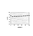
また、図13は、実施例1−2で測定した画像濃度と光沢度との関係をプロットしたもので、これによれば、画像濃度を10〜100%に変化させても、均一な光沢度が得られることが理解される。これに対し、図14は、比較例3で測定した画像濃度と光沢度との関係をプロットしたもので、上述した実施例1−2に比べ、画像濃度による光沢度の変化が見受けられることが理解される。 FIG. 13 is a plot of the relationship between the image density and the glossiness measured in Example 1-2. According to this plot, even when the image density is changed to 10 to 100%, the uniform glossiness is obtained. Is understood to be obtained. On the other hand, FIG. 14 is a plot of the relationship between the image density and the glossiness measured in Comparative Example 3. Compared with Example 1-2 described above, a change in the glossiness due to the image density can be seen. Understood.
そして、本実施例では、熱可塑性樹脂層が104Pa・s以下であれば良好な画像が得られた。このとき、熱可塑性樹脂層の粘度変化を測定した結果が、図15の図である。この粘度測定は、フローテスター粘度を測定したもので、荷重10kgf、直径5mm、昇温条件1℃/minとした。この結果から、熱可塑性樹脂層が110℃で104Pa・s以下であった。すなわち、このような条件であれば、トナー像を熱可塑性樹脂層に良好に埋め込むことができるようになる。 In this example, when the thermoplastic resin layer was 10 4 Pa · s or less, a good image was obtained. At this time, the result of measuring the viscosity change of the thermoplastic resin layer is shown in FIG. In this viscosity measurement, the flow tester viscosity was measured, and the load was 10 kgf, the diameter was 5 mm, and the temperature raising condition was 1 ° C./min. From this result, the thermoplastic resin layer was 10 4 Pa · s or less at 110 ° C. That is, under such conditions, the toner image can be satisfactorily embedded in the thermoplastic resin layer.
1…記録シート,2…定着ベルト 1 ... recording sheet, 2 ... fixing belt
Claims (12)
前記未定着トナー像と接する表面は、微小硬度が5以上30以下であり且つ光沢度Gs(20°)が50以上に設定されていることを特徴とする定着ベルト。 An endless fixing belt for use in a fixing device in which a surface contacts an unfixed toner image of a recording sheet carrying an unfixed toner image and is fixed by heating and pressing,
The fixing belt, wherein the surface in contact with the unfixed toner image has a microhardness of 5 to 30 and a glossiness Gs (20 °) of 50 or more.
前記微小硬度が6以上30以下であることを特徴とする定着ベルト。 The fixing belt according to claim 1.
The fixing belt having a micro hardness of 6 or more and 30 or less.
耐熱性ベルト基材の表面に弾性層又は更に離型層が積層されたものであることを特徴とする定着ベルト。 The fixing belt according to claim 1.
A fixing belt characterized in that an elastic layer or further a release layer is laminated on the surface of a heat-resistant belt substrate.
前記弾性層及び離型層は、フルオロカーボンシロキサンゴムを主成分とするものであることを特徴とする定着ベルト。 The fixing belt according to claim 3.
The fixing belt, wherein the elastic layer and the release layer are mainly composed of fluorocarbon siloxane rubber.
前記弾性層は、フッ素微粒子を分散させたフルオロカーボンシロキサンゴムを主成分とするものであることを特徴とする定着ベルト。 The fixing belt according to claim 3.
The fixing belt, wherein the elastic layer is mainly composed of fluorocarbonsiloxane rubber in which fluorine fine particles are dispersed.
前記定着ベルトとして請求項1記載のベルト部材を用いたことを特徴とする定着装置。 A fixing device for fixing an unfixed toner image on a recording sheet carrying an unfixed toner image by bringing the surface of a fixing belt into contact with the unfixed toner image and heating and pressing the recording sheet
A fixing device using the belt member according to claim 1 as the fixing belt.
記録シートは少なくともトナー像担持面側に熱可塑性樹脂層が設けられ、この熱可塑性樹脂層上にトナー像を定着させることを特徴とする定着装置。 The fixing device according to claim 6.
A fixing device, wherein a recording sheet is provided with a thermoplastic resin layer at least on a toner image carrying surface side, and a toner image is fixed on the thermoplastic resin layer.
前記トナー像の最上層は透明トナーであることを特徴とする定着装置。 The fixing device according to claim 7.
The fixing device according to claim 1, wherein the uppermost layer of the toner image is a transparent toner.
定着ニップ内の前記熱可塑性樹脂層の溶融粘度は、110℃の条件下にて104Pa・s以下となるように設定されていることを特徴とする定着装置。 The fixing device according to claim 7.
The fixing device, wherein the melt viscosity of the thermoplastic resin layer in the fixing nip is set to be 10 4 Pa · s or less under a condition of 110 ° C.
定着された後の記録シート上のトナー像は、当該記録シート内での異なる画像面積率での光沢度の差ΔGs(20°)が10以下に設定されていることを特徴とする定着装置。 The fixing device according to claim 7.
The fixing device, wherein the toner image on the recording sheet after being fixed has a gloss difference ΔGs (20 °) at different image area ratios within the recording sheet set to 10 or less.
請求項6記載の定着装置とを備えることを特徴とする画像形成装置。 An image forming engine for forming an unfixed toner image on a recording sheet;
An image forming apparatus comprising the fixing device according to claim 6.
前記定着ベルトが中間転写ベルトを兼用するものであることを特徴とする画像形成装置。 The image forming apparatus according to claim 11, wherein the image forming engine uses an intermediate transfer belt.
An image forming apparatus, wherein the fixing belt also serves as an intermediate transfer belt.
Priority Applications (1)
| Application Number | Priority Date | Filing Date | Title |
|---|---|---|---|
| JP2005360996A JP2007163902A (en) | 2005-12-14 | 2005-12-14 | Fixing belt and fixing device using the same, and image forming apparatus |
Applications Claiming Priority (1)
| Application Number | Priority Date | Filing Date | Title |
|---|---|---|---|
| JP2005360996A JP2007163902A (en) | 2005-12-14 | 2005-12-14 | Fixing belt and fixing device using the same, and image forming apparatus |
Publications (1)
| Publication Number | Publication Date |
|---|---|
| JP2007163902A true JP2007163902A (en) | 2007-06-28 |
Family
ID=38246842
Family Applications (1)
| Application Number | Title | Priority Date | Filing Date |
|---|---|---|---|
| JP2005360996A Pending JP2007163902A (en) | 2005-12-14 | 2005-12-14 | Fixing belt and fixing device using the same, and image forming apparatus |
Country Status (1)
| Country | Link |
|---|---|
| JP (1) | JP2007163902A (en) |
Cited By (5)
| Publication number | Priority date | Publication date | Assignee | Title |
|---|---|---|---|---|
| JP2009294644A (en) * | 2008-05-09 | 2009-12-17 | Canon Inc | Image forming system, program, and recording medium with program recorded thereon |
| JP2010152303A (en) * | 2008-11-21 | 2010-07-08 | Ricoh Co Ltd | Fixing member, and fixing device and image forming apparatus including the same |
| US8494385B2 (en) | 2010-02-25 | 2013-07-23 | Ricoh Company, Ltd. | Image forming apparatus |
| US8520261B2 (en) | 2010-10-28 | 2013-08-27 | Ricoh Company, Ltd. | Controller and halftone dot signal generating method capable of controlling glossiness of image |
| JP2013242389A (en) * | 2012-05-18 | 2013-12-05 | Tokai Rubber Ind Ltd | Endless belt |
-
2005
- 2005-12-14 JP JP2005360996A patent/JP2007163902A/en active Pending
Cited By (5)
| Publication number | Priority date | Publication date | Assignee | Title |
|---|---|---|---|---|
| JP2009294644A (en) * | 2008-05-09 | 2009-12-17 | Canon Inc | Image forming system, program, and recording medium with program recorded thereon |
| JP2010152303A (en) * | 2008-11-21 | 2010-07-08 | Ricoh Co Ltd | Fixing member, and fixing device and image forming apparatus including the same |
| US8494385B2 (en) | 2010-02-25 | 2013-07-23 | Ricoh Company, Ltd. | Image forming apparatus |
| US8520261B2 (en) | 2010-10-28 | 2013-08-27 | Ricoh Company, Ltd. | Controller and halftone dot signal generating method capable of controlling glossiness of image |
| JP2013242389A (en) * | 2012-05-18 | 2013-12-05 | Tokai Rubber Ind Ltd | Endless belt |
Similar Documents
| Publication | Publication Date | Title |
|---|---|---|
| US7139522B2 (en) | Image forming apparatus | |
| JP3945281B2 (en) | Image forming apparatus | |
| US7460821B2 (en) | Image heating apparatus including heating rotatable member and cooperating rubbing rotatable member | |
| US7079802B2 (en) | Fixing device with specific surface roughness | |
| US7515858B2 (en) | Fluorocarbon resin-coated member with a specified relative film density, manufacturing method thereof, fixing device using the member, and image forming apparatus using the device | |
| JP2005164721A (en) | Fixing apparatus and image forming apparatus | |
| WO2007023974A1 (en) | Image forming apparatus | |
| JP4834378B2 (en) | Fixing method, image forming method, fixing device, and image forming apparatus | |
| JP2007148430A (en) | Image forming apparatus | |
| JP2004086202A (en) | Electrophotographic fixing parts, electrophotographic fixing endless belt and heating roll belt type fixing device | |
| JP2005352297A (en) | Fixing device and image forming apparatus | |
| JP4019814B2 (en) | Electrophotographic label sheet and image forming method using the same | |
| CN101206448A (en) | Fixing device and image forming device | |
| JP6171574B2 (en) | Fixing pressure belt, fixing device, and image forming apparatus | |
| JP5553816B2 (en) | Fixing apparatus and image forming apparatus | |
| JP2005234001A (en) | Fixing device and image forming apparatus | |
| JP4821301B2 (en) | Fixing device and image forming apparatus using the same | |
| JP2009300593A (en) | Heating rotating body and image heating device equipped with the same | |
| JP7326874B2 (en) | Fixing device and fixing method | |
| JP3233349B2 (en) | Fixing device and fixing endless belt | |
| JP4577148B2 (en) | Image forming apparatus and image forming method | |
| JP2007161433A (en) | Image forming device | |
| JP2006235006A (en) | Fixing device and image forming apparatus | |
| JP2005084134A (en) | Heat fixing member, fixing device including the heat fixing member, and image forming apparatus | |
| JP2024010578A (en) | Resin belts for image forming devices, fixing belts, fixing devices, and image forming devices |