JP2007167659A - External device for controlling laser in ophthalmologic operation - Google Patents
External device for controlling laser in ophthalmologic operation Download PDFInfo
- Publication number
- JP2007167659A JP2007167659A JP2006343084A JP2006343084A JP2007167659A JP 2007167659 A JP2007167659 A JP 2007167659A JP 2006343084 A JP2006343084 A JP 2006343084A JP 2006343084 A JP2006343084 A JP 2006343084A JP 2007167659 A JP2007167659 A JP 2007167659A
- Authority
- JP
- Japan
- Prior art keywords
- patient
- software package
- remote control
- control device
- signal
- Prior art date
- Legal status (The legal status is an assumption and is not a legal conclusion. Google has not performed a legal analysis and makes no representation as to the accuracy of the status listed.)
- Pending
Links
- 238000001356 surgical procedure Methods 0.000 claims abstract description 12
- 238000000034 method Methods 0.000 claims description 18
- 210000004087 cornea Anatomy 0.000 claims description 8
- 230000001276 controlling effect Effects 0.000 claims description 4
- 238000002679 ablation Methods 0.000 claims description 3
- 230000000875 corresponding effect Effects 0.000 claims description 3
- 230000008859 change Effects 0.000 claims description 2
- 230000002596 correlated effect Effects 0.000 claims description 2
- 238000002271 resection Methods 0.000 claims 4
- 208000002177 Cataract Diseases 0.000 description 2
- 230000000694 effects Effects 0.000 description 2
- 238000000608 laser ablation Methods 0.000 description 2
- 238000002430 laser surgery Methods 0.000 description 2
- 238000003032 molecular docking Methods 0.000 description 2
- 230000008569 process Effects 0.000 description 2
- 238000010276 construction Methods 0.000 description 1
- 230000006735 deficit Effects 0.000 description 1
- 238000010586 diagram Methods 0.000 description 1
- 210000003128 head Anatomy 0.000 description 1
- 230000036512 infertility Effects 0.000 description 1
- 230000007246 mechanism Effects 0.000 description 1
- 238000002360 preparation method Methods 0.000 description 1
- 230000001225 therapeutic effect Effects 0.000 description 1
Images
Classifications
-
- G—PHYSICS
- G05—CONTROLLING; REGULATING
- G05G—CONTROL DEVICES OR SYSTEMS INSOFAR AS CHARACTERISED BY MECHANICAL FEATURES ONLY
- G05G1/00—Controlling members, e.g. knobs or handles; Assemblies or arrangements thereof; Indicating position of controlling members
- G05G1/30—Controlling members actuated by foot
- G05G1/305—Compound pedal co-operating with two or more controlled members
-
- A—HUMAN NECESSITIES
- A61—MEDICAL OR VETERINARY SCIENCE; HYGIENE
- A61F—FILTERS IMPLANTABLE INTO BLOOD VESSELS; PROSTHESES; DEVICES PROVIDING PATENCY TO, OR PREVENTING COLLAPSING OF, TUBULAR STRUCTURES OF THE BODY, e.g. STENTS; ORTHOPAEDIC, NURSING OR CONTRACEPTIVE DEVICES; FOMENTATION; TREATMENT OR PROTECTION OF EYES OR EARS; BANDAGES, DRESSINGS OR ABSORBENT PADS; FIRST-AID KITS
- A61F9/00—Methods or devices for treatment of the eyes; Devices for putting in contact-lenses; Devices to correct squinting; Apparatus to guide the blind; Protective devices for the eyes, carried on the body or in the hand
- A61F9/007—Methods or devices for eye surgery
- A61F9/008—Methods or devices for eye surgery using laser
- A61F9/00802—Methods or devices for eye surgery using laser for photoablation
- A61F9/00804—Refractive treatments
-
- A—HUMAN NECESSITIES
- A61—MEDICAL OR VETERINARY SCIENCE; HYGIENE
- A61F—FILTERS IMPLANTABLE INTO BLOOD VESSELS; PROSTHESES; DEVICES PROVIDING PATENCY TO, OR PREVENTING COLLAPSING OF, TUBULAR STRUCTURES OF THE BODY, e.g. STENTS; ORTHOPAEDIC, NURSING OR CONTRACEPTIVE DEVICES; FOMENTATION; TREATMENT OR PROTECTION OF EYES OR EARS; BANDAGES, DRESSINGS OR ABSORBENT PADS; FIRST-AID KITS
- A61F9/00—Methods or devices for treatment of the eyes; Devices for putting in contact-lenses; Devices to correct squinting; Apparatus to guide the blind; Protective devices for the eyes, carried on the body or in the hand
- A61F9/007—Methods or devices for eye surgery
- A61F9/008—Methods or devices for eye surgery using laser
- A61F9/00825—Methods or devices for eye surgery using laser for photodisruption
- A61F9/00836—Flap cutting
-
- A—HUMAN NECESSITIES
- A61—MEDICAL OR VETERINARY SCIENCE; HYGIENE
- A61F—FILTERS IMPLANTABLE INTO BLOOD VESSELS; PROSTHESES; DEVICES PROVIDING PATENCY TO, OR PREVENTING COLLAPSING OF, TUBULAR STRUCTURES OF THE BODY, e.g. STENTS; ORTHOPAEDIC, NURSING OR CONTRACEPTIVE DEVICES; FOMENTATION; TREATMENT OR PROTECTION OF EYES OR EARS; BANDAGES, DRESSINGS OR ABSORBENT PADS; FIRST-AID KITS
- A61F9/00—Methods or devices for treatment of the eyes; Devices for putting in contact-lenses; Devices to correct squinting; Apparatus to guide the blind; Protective devices for the eyes, carried on the body or in the hand
- A61F9/007—Methods or devices for eye surgery
- A61F9/008—Methods or devices for eye surgery using laser
- A61F2009/00861—Methods or devices for eye surgery using laser adapted for treatment at a particular location
- A61F2009/00872—Cornea
Landscapes
- Health & Medical Sciences (AREA)
- Ophthalmology & Optometry (AREA)
- Physics & Mathematics (AREA)
- Engineering & Computer Science (AREA)
- Life Sciences & Earth Sciences (AREA)
- Animal Behavior & Ethology (AREA)
- Nuclear Medicine, Radiotherapy & Molecular Imaging (AREA)
- Biomedical Technology (AREA)
- Heart & Thoracic Surgery (AREA)
- Vascular Medicine (AREA)
- Optics & Photonics (AREA)
- Surgery (AREA)
- General Health & Medical Sciences (AREA)
- Public Health (AREA)
- Veterinary Medicine (AREA)
- General Physics & Mathematics (AREA)
- Automation & Control Theory (AREA)
- Laser Surgery Devices (AREA)
- Radiation-Therapy Devices (AREA)
- Selective Calling Equipment (AREA)
Abstract
Description
本発明は,目のレーザ手術に関するものであり,より特定すれば視力障害を矯正するためのレーザ切除手術,更に特定すればレーザ手術デバイスの制御デバイスのためのシステム及び方法に関する。 The present invention relates to laser surgery for eyes, and more particularly to laser ablation surgery for correcting vision impairment, and more particularly to systems and methods for control devices for laser surgery devices.
目の屈折手術において,レーザシステムは典型的にはキーボード及びマウス,又はシステムに組み込まれたハードウェアボタンを用いて制御される。そのような永続的に装着されたデバイスは位置を変更することができず,構成することもできない。また特に,1つの目からもう1つの目に移るときなど,処置のある部分で手が届きにくいことがある。 In refractive eye surgery, the laser system is typically controlled using a keyboard and mouse, or hardware buttons built into the system. Such permanently attached devices cannot change position and cannot be configured. Also, especially when moving from one eye to another, it may be difficult to reach the part where treatment is performed.
電子デバイスを操作するために遠隔制御デバイスを使うことはよく知られている。白内障及び硝子体処置においても外部デバイスの使用が知られている。 It is well known to use remote control devices to operate electronic devices. The use of external devices is also known for cataract and vitreous treatment.
角膜の屈折手術のような手術処置の間に用いるための,位置及び機能に柔軟性がある遠隔制御デバイスを提供することが望まれる。 It would be desirable to provide a remote control device that is flexible in position and function for use during surgical procedures such as corneal refractive surgery.
本発明は,目の屈折手術に用いるデバイスを制御するためのシステム及び方法に関する。本システムは,プロセッサと,前記プロセッサと通信するコントローラと,前記コントローラと通信する治療レーザと,前記プロセッサと通信する信号受信器とを備える。遠隔制御デバイスは複数の入力要素を備える前記信号受信器と通信する。各入力要素は活性化されたとき前記信号受信器が受信できる離散信号を送信するように構成される。前記離散信号の少なくとも1つが前記コントローラの通知する操作に対応する。ソフトウェアパッケージは前記プロセッサ上に常駐し,前記信号受信器からのデータを少なくとも前記コントローラを指示するための信号に変換するように適応させられる。 The present invention relates to a system and method for controlling a device used in refractive surgery of the eye. The system includes a processor, a controller in communication with the processor, a treatment laser in communication with the controller, and a signal receiver in communication with the processor. A remote control device communicates with the signal receiver comprising a plurality of input elements. Each input element is configured to transmit a discrete signal that can be received by the signal receiver when activated. At least one of the discrete signals corresponds to an operation notified by the controller. A software package resides on the processor and is adapted to convert data from the signal receiver into a signal for instructing at least the controller.
目の屈折手術に用いるデバイスを制御するためのシステムを構成する方法は,複数の入力要素を備える遠隔制御デバイスであって,各入力要素は活性化されたときに離散信号を送信するように構成する遠隔制御デバイスを提供するステップを有する。各離散信号は,屈折レーザ手術システムのハードウェア要素によって実装される操作に電子的に対応付けられる。プロセッサ上に常駐するソフトウェアパッケージは,前記遠隔制御デバイスからの信号データを受信し,前記電子的対応付けに基づいて前記ハードウェア要素の制御データに変換するように適応させられる。前記ソフトウェアパッケージはまた,前記制御データと相関する制御信号を前記ハードウェア要素に出力するように適応させられる。 A method of configuring a system for controlling a device for refractive eye surgery is a remote control device comprising a plurality of input elements, each input element configured to transmit a discrete signal when activated. Providing a remote control device. Each discrete signal is electronically associated with an operation implemented by hardware elements of a refractive laser surgical system. A software package resident on the processor is adapted to receive signal data from the remote control device and convert it to control data of the hardware element based on the electronic association. The software package is also adapted to output a control signal correlated to the control data to the hardware element.
本発明の効果は多岐にわたる。遠隔制御デバイスの利用によって,機動性が得られ,かつ複数のユーザが決めた位置からの制御が可能になり,システムを扱う際の柔軟性が増加する。例えば,制御位置をそれぞれの目に対応して反対側に切り替えることができ,それによって適切な手を使うことができ,又は単純に,同時に複数の位置にある制御ユニットを選択することができる。レーシック手術における現在の実践法に関して,本発明はマイクロケラトームの準備のような同時に行う複数の仕事から手術助手を解放することができ,それでもなお遠隔制御デバイスを介してグラフィックユーザインタフェースの制御を維持することができる。 The effects of the present invention are diverse. By using a remote control device, mobility is obtained and control from a position determined by a plurality of users is possible, thereby increasing flexibility in handling the system. For example, the control position can be switched to the opposite side corresponding to each eye, so that appropriate hands can be used, or simply control units in multiple positions can be selected simultaneously. With respect to current practice in LASIK surgery, the present invention can free the surgical assistant from multiple simultaneous tasks such as microkeratome preparation and still maintain control of the graphic user interface via a remote control device be able to.
物理的柔軟性及び機動性に加えて,外部制御もまた構成可能性を増加させ,ユーザが自分の好みに合った制御機能を指定することができるので,人間工学及び利便性を改善する。 In addition to physical flexibility and mobility, external control also increases the configurability and improves ergonomics and convenience because the user can specify control functions that suit their preferences.
制御位置及び構成を最適化することによって,操作者と制御ユニットの間に直接の見通しがなくても遠隔制御デバイスを操作することができる。これによって固定されたハードウェアに装着された制御部又は別々のユーザインタフェースを探すために手術が中断される可能性が取り除かれ,更に手術過程が改善される。更に,システムからハードウェアコンポーネントが取り除かれるのでスペースが節約になり,起こりうる電磁的干渉問題も除去される。 By optimizing the control position and configuration, the remote control device can be operated without direct visibility between the operator and the control unit. This eliminates the possibility of the surgery being interrupted to look for controls or separate user interfaces mounted on fixed hardware, and further improves the surgical process. In addition, hardware components are removed from the system, saving space and eliminating possible electromagnetic interference problems.
機構及び操作方法双方に関して本発明を特徴付ける特徴は,その更なる目的及び利点と共に,以下の記述と付随する図面とからより良く理解されるであろう。添付の図面は例示及び説明のためのものであり,本発明の範囲を定義するものではないことは直ちに理解されるであろう。本願発明によって達成されるこれらの及びほかの目的,並びに提供される利点は,以下の記述を付随する図面と共に読むことによって,より十分に明らかになるであろう。 The features that characterize the present invention both in terms of mechanism and method of operation, together with its further objects and advantages, will be better understood from the following description and the accompanying drawings. It will be readily appreciated that the attached drawings are for purposes of illustration and description and do not define the scope of the invention. These and other objects achieved by the present invention and the advantages provided will become more fully apparent when the following description is read in conjunction with the accompanying drawings.
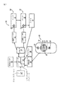
ここで図1〜5を参照して本発明の好ましい実施例を説明する。角膜レーザ切除を行うシステム10は,例えばエキシマレーザであってもよい間欠治療レーザ11を備える(図1)。角膜フラップを切断する切断レーザ12もあってよい。患者は典型的にはベッド13の上に寝かせられ,ベッドは患者の角膜15が切断レーザ12で処置される第1の位置14と,患者の角膜15が治療レーザ11で処置される第2の位置16との間を移動することができる。
A preferred embodiment of the present invention will now be described with reference to FIGS. A
システム10は,プロセッサ17及びその上に常駐するソフトウェア18を備える。レーザコントローラ19と,ディスプレイデバイス20と,信号受信器21とは,プロセッサ17と通信する。遠隔制御デバイス22は,信号受信器21と通信することができ,複数の入力要素23〜29を備える。各入力要素23〜29は,活性化されると信号受信器21が受信できる,例えば赤外線又は無線周波数範囲の離散信号を送信するように構成される。離散信号の少なくとも1つが,コントローラ19が通知する操作に対応付けられる。ソフトウェアパッケージ18は,信号受信器21からのデータをコントローラ19及びディスプレイデバイス20のようなハードウェア要素を指示する信号に変換するように適応させられる。
The
ディスプレイデバイス20は,医師/ユーザに例えば患者リストと,患者用ベッドの位置と,カメラ30が提供する患者の角膜15の画像とを表示するためのグラフィックユーザインタフェース(GUI)を備えてもよい。ソフトウェア18が患者リストを表示するように指示しているときは,遠隔制御デバイス22の上矢印23及び下矢印24を用いて患者リストをスクロールさせることができ,決定キー25で特定の患者の名前を選択することができる。そのような選択を行うと,ソフトウェア18はその選択された患者の所定の切除輪郭を取得する。
The
ユーザが目の画像を見たいときは,遠隔制御デバイス22のユーザ定義キー26を使って,ディスプレイ20にカメラ30からの画像を表示するように指示することができる。そしてソフトウェア18は,自動的にその画像を例えば角膜など所望の位置に合わせるように処理することができる。
When the user wants to see the eye image, the user-defined
患者用ベッド13を第1の位置14と第2の位置16との間で移動させる方向もまた,遠隔制御デバイス22の上キー23,下キー24,右キー27,左キー28でメニュー項目をスクロールさせることによって調整することができる。前のGUIメニューに戻る信号は,戻るボタン29を選択することによって送信させることができる。
The direction in which the
遠隔制御デバイス22上の入力要素23〜29は制御デバイスに結線されていないので,当技術の当業者であれば,遠隔制御デバイスが送信する離散信号をソフトウェアパッケージ18が実現する任意の所望の方法でユーザが定義し,構成することができることは理解できるであろう。更に各入力要素23〜29はまた,例えばさまざまな条件下で,またさまざまな機能のために,一組の条件下で入力要素23〜29が一組の制御に対応付けられ,かつもう1つの条件の組においては,入力要素23〜29が所望の別の制御の組に対応付けることができるように多様な機能を持つようにプログラムしてもよい。GUIは例えば,プログラムされた入力要素の機能性がユーザに明確であるように,システムの状態を明確に示すようにプログラムすることができる。
Since the input elements 23-29 on the
遠隔制御デバイス22はいくつかある方法のどれによって組み立てられても良く,例示された形状は限定を意図したものではない。遠隔制御デバイス22は,例えば顕微鏡から直接患者を見通すことを妨げないように,できるだけ薄いことが望ましい。ボタン23〜29は,操作が容易なように遠隔制御デバイス22に上面に位置するのが望ましい。ボタン23〜29は,すばやく探すことができるように独特の形状を有し,高さがあって分離しているのが望ましい。例えば矢印ボタン23,24,27,28は,曲線状の内側及びとがった外縁を有してもよい。決定ボタン25は矢印ボタン23,24,27,28に対して中心に位置し,矢印ボタン23,24,27,28と同じ高さで,探すのが容易なように真ん中に出っ張りがあってもよい。例としての実施例における自動位置合わせボタン26は,矢印ボタン23,24,27,28の下に位置し,出っ張りのない決定ボタン25と類似の形状をしている。戻るボタン29はここでは正方形であり,矢印ボタン23,24,27,28の上に位置している。最適なメニュースクロール及びユーザフィードバックのために,ボタン23〜29を押下するとクリック音を伴うのが望ましい。ボタン23〜29はまた,薄暗い環境でもよく見えるように,バックライトを当てるのが望ましい。
The
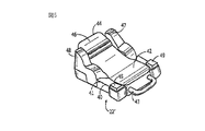
もう1つの実施例においては,手持ち遠隔制御デバイス22に加え,又はその代わりに足踏スイッチ22’を提供してもよい(図5)。足踏スイッチ22’は例えば,白内障手術のように医師の手がふさがっているほかの医療処置においてシステムを制御するために用いられるようなデバイスを備えてもよい。足踏スイッチ22’の実施例の効果の中には,制御機能を助手に委任できること,また医師自身が足踏スイッチ22’を操作するとき,医師の完全な無菌状態を保証することがある。足踏スイッチ22’は,ほぼ平面状の底面41を有する台40と,人間の足をその上に乗せられるように形どられ,寸法決めされた上面42とを備えてもよく,また前縁43から後縁44に向けて上方に角度を持ってもよい。足踏スイッチ22’は固定機能を制御しないと考えられるが,これば制限として意図するものではない。
In another embodiment, a foot switch 22 'may be provided in addition to or instead of the handheld remote control device 22 (FIG. 5). The foot switch 22 'may comprise a device such as that used to control the system in other medical procedures that are occupied by a physician, such as cataract surgery. Among the effects of the embodiment of the foot switch 22 'is that the control function can be delegated to the assistant and that the doctor can guarantee complete sterility when operating the foot switch 22'. The foot switch 22 'may comprise a platform 40 having a substantially planar
ここでは押下できるボタンである複数の入力要素45〜49は,上記のように活性化されると信号受信器21が受信できる例えば赤外線又は無線周波数範囲の離散信号を送信するように構成される。離散信号の少なくとも1つは,コントローラ19が通知する操作に対応付けられる。ソフトウェアパッケージ18は,信号受信器21からのデータを,コントローラ19及びディスプレイデバイス20のようなハードウェア要素を指示する信号に変換するように適応させられる。
Here, the plurality of input elements 45 to 49, which are buttons that can be pressed, are configured to transmit, for example, infrared or radio frequency discrete signals that can be received by the
図5に示すような特定の実施例においては,ボタン45は「戻る」ボタンであり,ボタン46は「決定」ボタンであり,ボタン47は上/下ボタンであり,ボタン48は左/右ボタンであり,そしてボタン49はユーザ定義ボタンである。
In a particular embodiment as shown in FIG. 5, button 45 is a “back” button,
もう1つの選択肢では,ボタンで操作する遠隔制御デバイスの代わりにジョイスティック22”を備えてもよい。
In another option, a
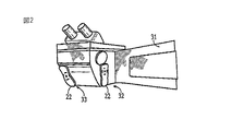
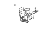
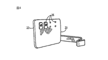
遠隔制御デバイス22自体はシステム10内のさまざまな位置に装着することができる。例えば,図2及び3に示すように顕微鏡アーム31の上の複数の位置32,33のいずれか,又は医師用椅子35のひじ掛け34の上に,例えば磁石又はほかの種類の連結方法で装着できる。遠隔制御デバイス22は,医師の体又は衣服,若しくはカートにさえ装着することができる。レーザヘッド上に装着すれば,いずれかの手の指で制御することを選択することができる。更に,複数の遠隔制御デバイス22を,操作が容易なように複数の位置に置くこともできる。遠隔制御デバイス22はシステム10の多様な位置のいずれでも同様に良好に再充電することができ,図4に示すようにディスプレイ20の背面には,電源に接続された複数のドッキングステーション36を備えている。
The
以上の記述において,簡潔性,明瞭性及び理解性のために特定の用語を用いたが,それによって先行技術の要求条件を超えて不必要な制限を強いるものではない。なぜならばそのような単語はここでは説明のために用いられており,広く解釈されるように意図されているからである。更に,ここに例示され説明された装置の実施例は例であって,本発明の範囲はその構造のとおりの詳細によって制限されない。 In the above description, specific terms have been used for the sake of brevity, clarity and comprehension, but this does not impose unnecessary restrictions beyond the requirements of the prior art. This is because such words are used here for explanation and are intended to be interpreted broadly. Furthermore, the device embodiments illustrated and described herein are examples, and the scope of the invention is not limited by the details of its construction.
以上,本発明が説明された。その好ましい実施例の構造,操作及び利用と,それによって得られる利点があり,新しくかつ有用な結果と,新規で有用な構造と,当技術の当業者には明白なそれらの合理的な機械的均等物とは,本願請求項において明らかにされている。 The present invention has been described above. The structure, operation and use of the preferred embodiment, and the advantages obtained thereby, new and useful results, new and useful structures, and their reasonable mechanical properties apparent to those skilled in the art. Equivalents are specified in the claims.
10 システム
11 治療レーザ
12 切断レーザ
17 プロセッサ
18 ソフトウェアパッケージ
19 コントローラ
20 ディスプレイデバイス
21 信号受信器
22 遠隔制御デバイス
10 System 11 Treatment Laser 12 Cutting Laser 17
Claims (18)
プロセッサと,
前記プロセッサと通信するコントローラと,
前記コントローラと通信する治療レーザと,
前記プロセッサと通信する信号受信器と,
複数の入力要素を備える前記信号受信器と通信する遠隔制御デバイスであって,各入力要素は活性化されたとき前記信号受信器が受信できる離散信号を送信するように構成され,前記離散信号の少なくとも1つが前記コントローラの通知する操作に対応する遠隔制御デバイスと,
前記プロセッサ上に常駐するソフトウェアパッケージであって,前記信号受信器からのデータを少なくとも前記コントローラを指示するための信号に変換するように適応させたソフトウェアパッケージとを備えるシステム。 A system for controlling a device used for refractive surgery of the eye,
A processor,
A controller in communication with the processor;
A treatment laser in communication with the controller;
A signal receiver in communication with the processor;
A remote control device in communication with the signal receiver comprising a plurality of input elements, each input element configured to transmit a discrete signal that can be received by the signal receiver when activated, At least one remote control device corresponding to an operation notified by the controller;
A software package resident on the processor, the software package adapted to convert data from the signal receiver into at least a signal for indicating the controller.
複数の入力要素を備える遠隔制御デバイスであって,各入力要素が活性化されたときに離散信号を送信するように構成する遠隔制御デバイスを提供するステップと,
各離散信号を,屈折レーザ手術システムのハードウェア要素によって実装される操作に電子的に対応付けるステップと,
プロセッサ上に常駐するソフトウェアパッケージであって,該ソフトウェアパッケージを,前記遠隔制御デバイスからの信号データを受信し,前記電子的対応付けに基づいて前記ハードウェア要素の制御データに変換し,かつ前記制御データと相関する制御信号を前記ハードウェア要素に出力するように適応させたソフトウェアパッケージを提供するステップとを有する方法。 A method of configuring a system for controlling a device used for refractive eye surgery,
Providing a remote control device comprising a plurality of input elements, the remote control device being configured to transmit a discrete signal when each input element is activated;
Electronically associating each discrete signal with an operation implemented by hardware elements of a refractive laser surgical system;
A software package resident on a processor that receives signal data from the remote control device, converts the software package into control data of the hardware element based on the electronic association, and the control Providing a software package adapted to output a control signal correlated with data to the hardware element.
Applications Claiming Priority (1)
| Application Number | Priority Date | Filing Date | Title |
|---|---|---|---|
| US75301005P | 2005-12-22 | 2005-12-22 |
Publications (1)
| Publication Number | Publication Date |
|---|---|
| JP2007167659A true JP2007167659A (en) | 2007-07-05 |
Family
ID=37991586
Family Applications (1)
| Application Number | Title | Priority Date | Filing Date |
|---|---|---|---|
| JP2006343084A Pending JP2007167659A (en) | 2005-12-22 | 2006-12-20 | External device for controlling laser in ophthalmologic operation |
Country Status (9)
| Country | Link |
|---|---|
| US (1) | US20070149956A1 (en) |
| EP (1) | EP1803426A1 (en) |
| JP (1) | JP2007167659A (en) |
| KR (1) | KR100850126B1 (en) |
| AU (1) | AU2006252150A1 (en) |
| BR (1) | BRPI0605524A (en) |
| CA (1) | CA2571968A1 (en) |
| MX (1) | MXPA06015000A (en) |
| TW (1) | TW200730159A (en) |
Cited By (1)
| Publication number | Priority date | Publication date | Assignee | Title |
|---|---|---|---|---|
| JP2016524871A (en) * | 2013-06-06 | 2016-08-18 | マッケ・ゲゼルシャフトミットベシュレンクターハフトゥング | Method and apparatus for remotely controlling a medical device using a remote control device |
Families Citing this family (6)
| Publication number | Priority date | Publication date | Assignee | Title |
|---|---|---|---|---|
| US8109981B2 (en) | 2005-01-25 | 2012-02-07 | Valam Corporation | Optical therapies and devices |
| US20090005789A1 (en) * | 2007-06-26 | 2009-01-01 | Charles Steven T | Force Sensitive Foot Controller |
| US9240110B2 (en) | 2011-10-20 | 2016-01-19 | Alcon Research, Ltd. | Haptic footswitch treadle |
| US9066784B2 (en) * | 2011-12-19 | 2015-06-30 | Alcon Lensx, Inc. | Intra-surgical optical coherence tomographic imaging of cataract procedures |
| US10983604B2 (en) | 2018-05-16 | 2021-04-20 | Alcon Inc. | Foot controlled cursor |
| US11740648B2 (en) * | 2019-08-01 | 2023-08-29 | Alcon Inc. | Surgical footswitch having elevated auxiliary buttons |
Family Cites Families (13)
| Publication number | Priority date | Publication date | Assignee | Title |
|---|---|---|---|---|
| US6099522A (en) * | 1989-02-06 | 2000-08-08 | Visx Inc. | Automated laser workstation for high precision surgical and industrial interventions |
| DE69727675T2 (en) * | 1996-05-30 | 2004-12-02 | Technolas Gmbh Ophthalmologische Systeme | EXCIMER LASER SYSTEM FOR EYE SURGERY |
| US5891132A (en) * | 1996-05-30 | 1999-04-06 | Chiron Technolas Gmbh Opthalmologische Systeme | Distributed excimer laser surgery system |
| US6351678B1 (en) * | 1997-11-07 | 2002-02-26 | Hill-Rom Services, Inc. | Medical equipment controller |
| EP1175182B1 (en) * | 1999-04-07 | 2008-10-22 | AMO Manufacturing USA, LLC | Improved interface for laser eye surgery |
| US6280436B1 (en) * | 1999-08-10 | 2001-08-28 | Memphis Eye & Cataract Associates Ambulatory Surgery Center | Eye tracking and positioning system for a refractive laser system |
| ATE508717T1 (en) * | 2000-09-01 | 2011-05-15 | Alexander Dybbs | OPHTHALMIC SURGICAL SYSTEM |
| EP1417943A1 (en) * | 2001-04-19 | 2004-05-12 | Intralase Corp. | Method for photodisruption of the eye |
| US20030093503A1 (en) * | 2001-09-05 | 2003-05-15 | Olympus Optical Co., Ltd. | System for controling medical instruments |
| US20030208189A1 (en) * | 2001-10-19 | 2003-11-06 | Payman Gholam A. | Integrated system for correction of vision of the human eye |
| JP4171616B2 (en) | 2002-06-24 | 2008-10-22 | 株式会社ニデック | Corneal surgery device and corneal resection amount determination device |
| US8834457B2 (en) * | 2004-09-22 | 2014-09-16 | Cao Group, Inc. | Modular surgical laser systems |
| DE202005018911U1 (en) * | 2005-06-02 | 2006-03-09 | Wavelight Laser Technologie Ag | Refractive ophthalmology surgery device for correcting defective vision, has two treatment stations in which patient is subjected to different treatments, and couch that is moved from one treatment station to other station |
-
2006
- 2006-12-13 US US11/609,983 patent/US20070149956A1/en not_active Abandoned
- 2006-12-14 EP EP06126145A patent/EP1803426A1/en not_active Withdrawn
- 2006-12-19 MX MXPA06015000A patent/MXPA06015000A/en not_active Application Discontinuation
- 2006-12-19 TW TW095147593A patent/TW200730159A/en unknown
- 2006-12-20 AU AU2006252150A patent/AU2006252150A1/en not_active Abandoned
- 2006-12-20 JP JP2006343084A patent/JP2007167659A/en active Pending
- 2006-12-21 KR KR1020060131697A patent/KR100850126B1/en not_active Expired - Fee Related
- 2006-12-21 CA CA002571968A patent/CA2571968A1/en not_active Abandoned
- 2006-12-22 BR BRPI0605524-9A patent/BRPI0605524A/en not_active IP Right Cessation
Cited By (1)
| Publication number | Priority date | Publication date | Assignee | Title |
|---|---|---|---|---|
| JP2016524871A (en) * | 2013-06-06 | 2016-08-18 | マッケ・ゲゼルシャフトミットベシュレンクターハフトゥング | Method and apparatus for remotely controlling a medical device using a remote control device |
Also Published As
| Publication number | Publication date |
|---|---|
| KR100850126B1 (en) | 2008-08-04 |
| AU2006252150A1 (en) | 2007-07-12 |
| CA2571968A1 (en) | 2007-06-22 |
| MXPA06015000A (en) | 2008-10-17 |
| US20070149956A1 (en) | 2007-06-28 |
| TW200730159A (en) | 2007-08-16 |
| EP1803426A1 (en) | 2007-07-04 |
| BRPI0605524A (en) | 2007-10-16 |
| KR20070066917A (en) | 2007-06-27 |
Similar Documents
| Publication | Publication Date | Title |
|---|---|---|
| US12426976B2 (en) | User interface for controlling a surgical system | |
| JP6034509B2 (en) | Ophthalmic surgery system and control method thereof | |
| JP4233261B2 (en) | Remote control of medical devices using voice recognition and foot control | |
| US7317954B2 (en) | Virtual control of electrosurgical generator functions | |
| US9795507B2 (en) | Multifunction foot pedal | |
| CN110115631A (en) | The master console of operating robot | |
| JP2023520191A (en) | Virtual console for controlling surgical robots | |
| AU2007281806A1 (en) | Surgical machine with removable display | |
| JP2009511166A (en) | Foot controller | |
| KR100850126B1 (en) | External devices and associated methods for controlling the laser during laser ablation surgery on the cornea | |
| JP7343249B1 (en) | surgical support equipment | |
| JP6043420B1 (en) | Medical medical system, medical medical device, communication device, and method for preventing erroneous operation of medical medical device | |
| AU2004298999A1 (en) | Virtual control of electrosurgical generator functions | |
| AU2015343409A1 (en) | Multifunction foot pedal | |
| JP7401155B2 (en) | Surgical support equipment | |
| EP4230150A1 (en) | Wearable foot controller for surgical equipment and related methods | |
| US20240315680A1 (en) | Wearable foot controller for surgical equipment and related methods | |
| EP3744281B1 (en) | Microscope system and method for operating a surgical microscope | |
| EA027292B1 (en) | Method for controlling an operating table with a foot-operated controller |
Legal Events
| Date | Code | Title | Description |
|---|---|---|---|
| A131 | Notification of reasons for refusal |
Free format text: JAPANESE INTERMEDIATE CODE: A131 Effective date: 20090811 |
|
| A02 | Decision of refusal |
Free format text: JAPANESE INTERMEDIATE CODE: A02 Effective date: 20100126 |