JP2007168917A - Sheet processing apparatus and image forming system - Google Patents
Sheet processing apparatus and image forming system Download PDFInfo
- Publication number
- JP2007168917A JP2007168917A JP2005364737A JP2005364737A JP2007168917A JP 2007168917 A JP2007168917 A JP 2007168917A JP 2005364737 A JP2005364737 A JP 2005364737A JP 2005364737 A JP2005364737 A JP 2005364737A JP 2007168917 A JP2007168917 A JP 2007168917A
- Authority
- JP
- Japan
- Prior art keywords
- guide plate
- sheet
- processing apparatus
- image forming
- sheet processing
- Prior art date
- Legal status (The legal status is an assumption and is not a legal conclusion. Google has not performed a legal analysis and makes no representation as to the accuracy of the status listed.)
- Granted
Links
Images

Landscapes
- Feeding Of Articles By Means Other Than Belts Or Rollers (AREA)
- Folding Of Thin Sheet-Like Materials, Special Discharging Devices, And Others (AREA)
Abstract
【課題】装置の小型化をはかり、かつ、シートの搬送姿勢の補正を確実にすることができるシート処理装置及び画像形成システムを提供すること。
【解決手段】画像形成装置によって画像形成されたシートを、スティプル、仕分け、パンチ、から選ばれた1つ以上の処理を行うシート処理装置において、ガイド板が、上下に備えられた入口ガイド板3a,3bの少なくとも一方と、中継ガイド板4と、を一体としていることを特徴とするシート処理装置200及び画像形成システムを提供することができる。
【選択図】図2To provide a sheet processing apparatus and an image forming system capable of downsizing the apparatus and ensuring correction of a sheet conveying posture.
In a sheet processing apparatus that performs one or more processing selected from stipple, sorting, and punching on a sheet that has been imaged by an image forming apparatus, an inlet guide plate 3a having upper and lower guide plates is provided. , 3b and the relay guide plate 4 are integrated, the sheet processing apparatus 200 and the image forming system can be provided.
[Selection] Figure 2
Description
本発明は、画像形成済みのシートをスティプル等の後処理を施すシート処理装置及び画像形成システムに関するものである。特に、入口ガイド板を有するシート処理装置及び画像形成システムに関するものである。 The present invention relates to a sheet processing apparatus and an image forming system for performing post-processing such as stippling on an image-formed sheet. In particular, the present invention relates to a sheet processing apparatus having an entrance guide plate and an image forming system.
搬入されてきたシート、すなわち、画像形成装置から受け取ったシートの搬送姿勢を補正するために、斜めに搬送されてきたシートは先端が均一に搬送ローラのニップに突き当たらなければならないが、搬送ローラに突き当たる部分に時間差が生じるため、先に搬送ローラに突き当たったシート部分の下流部は撓もうとする。この撓みが無理なく行われるためには、入口ガイド板と中継ガイド板間の距離を離しておかなければ、撓むときにシートが当接して撓みにくくなったり、入口ガイド板と中継ガイド板間にシートが詰まってしまったり、シートにダメージを与えてしまう場合や、シート先端が均一に搬送ローラに突き当たらなくなってしまう場合がある。
そこで、特許文献1には、搬入されてきた用紙の先端を用紙搬送方向最上流側に設けた搬送ローラ対に当接させ、用紙先端が停止した状態で用紙をさらに送り込んで用紙先端の位置を前記搬送ローラ対のニップで揃え、搬送姿勢を補正した後、後段に送り出し、所定の処理を施して排紙する用紙処理装置において、前記搬送ローラ対に対して用紙をガイドする一対のガイド板に、前記搬送ローラ対に用紙が当接した後の用紙の撓みを許容する空間部を設けたことが、開示されている。
一般に、搬送経路内で用紙が撓んだときに、搬送経路の用紙面と対向するガイド板の間隔が小さい場合には波状になったりして一方向にきれいに撓むことができないので、用紙先端が平均して搬送ローラのニップに当接することができない。そのため、用紙の搬送姿勢補正が確実に行えない。
そこで、特許文献1のように用紙の撓みを許容する空間部を設けると、この空間部で用紙が一方向に綺麗に撓むことができるようになり、後段での用紙搬送姿勢補正が確実に行え、用紙を確実に意図した方向に撓ませて、用紙の搬送姿勢補正を確実に行うことができる用紙処理装置及び画像形成システムを提供することができた。
In order to correct the transport posture of the sheet that has been carried in, that is, the sheet received from the image forming apparatus, the front end of the sheet that has been transported obliquely must hit the nip of the transport roller uniformly. Since a time difference occurs in the portion that abuts on the sheet, the downstream portion of the sheet portion that abuts on the conveyance roller first tries to bend. In order for this bending to be performed without difficulty, if the distance between the entrance guide plate and the relay guide plate is not set apart, the sheet will come into contact with it when bent, making it difficult to bend, or between the entrance guide plate and the relay guide plate. The sheet may become clogged, the sheet may be damaged, or the front end of the sheet may not uniformly hit the conveying roller.
Therefore, in
In general, when the paper bends in the transport path, if the distance between the guide plates facing the paper surface of the transport path is small, it will be wavy and cannot be bent neatly in one direction. However, on the average, they cannot contact the nip of the transport roller. Therefore, it is not possible to reliably correct the paper transport posture.
Therefore, if a space that allows the sheet to bend is provided as in
しかしながら、特許文献1の方法ではその空間を確保するのに入口ガイド板と中継ガイド板間が長くなるため、その分装置が大型になってしまうという問題点があった。
そこで、本発明は上記問題点に鑑みてなされたものであり、その課題は、装置の小型化をはかり、かつ、シートの搬送姿勢の補正を確実にすることができるシート処理装置及び画像形成システムを提供することである。
また、入口ガイド板の強度と取り付け性を確保し、取り付ける画像形成装置の変更に合わせ、中継ガイド板のみ変更して対応することができるシート処理装置及び画像形成システムを提供することである。
さらに、2部材のガイド板の片方のみが歪むようにし、他物体との衝突時の損害を最小限に押えることができるシート処理装置及び画像形成システムを提供することである。
However, the method of
Accordingly, the present invention has been made in view of the above-described problems, and the problems thereof are a sheet processing apparatus and an image forming system capable of reducing the size of the apparatus and ensuring correction of the sheet conveying posture. Is to provide.
It is another object of the present invention to provide a sheet processing apparatus and an image forming system that can ensure the strength and mountability of an entrance guide plate and can change only the relay guide plate in accordance with the change of the image forming apparatus to be attached.
It is another object of the present invention to provide a sheet processing apparatus and an image forming system in which only one of the two-member guide plates is distorted so that damage at the time of collision with another object can be minimized.
上記課題を解決する手段である本発明の特徴を以下に挙げる。
本発明は、画像形成装置によって画像形成されたシートを、スティプル、仕分け、パンチ、から選ばれた1つ以上の処理を行うシート処理装置において、前記シート処理装置は、ガイド板が、上下に備えられた入口ガイド板の少なくとも一方と、中継ガイド板と、を一体としていることを特徴とするシート処理装置である。
本発明は、一体となっていないガイド板が、入口ガイド板と中継ガイド板の2部材で形成されることを特徴とするシート処理装置である。
本発明は、入口ガイド板と中継ガイド板を一体となっていないガイド板が、一体となっているガイド板より突出していることを特徴とする。ここで、突出とは、「一体となっていないガイド板が、排紙コロ側に長くなっていて、突き出ていること」をいう。
本発明は、画像形成装置から排紙されたシートが、入口ガイド板と中継ガイド板を一体となっていないガイド板に突き当たるようにしたことを特徴とする。
また、本発明は、画像形成システムは、前記記載のシート処理装置を備えたことを特徴とする画像形成システムである。
The features of the present invention, which is a means for solving the above problems, are listed below.
The present invention relates to a sheet processing apparatus that performs one or more processes selected from stipple, sorting, and punching on a sheet imaged by an image forming apparatus. The sheet processing apparatus includes guide plates that are provided above and below. The sheet processing apparatus is characterized in that at least one of the entrance guide plate and the relay guide plate are integrated.
The present invention is a sheet processing apparatus in which a guide plate that is not integrated is formed of two members, an inlet guide plate and a relay guide plate.
The present invention is characterized in that a guide plate in which the entrance guide plate and the relay guide plate are not integrated protrudes from the integrated guide plate. Here, the term “protrusion” means that “the guide plate that is not integrated is long and protrudes toward the sheet discharge roller side”.
The present invention is characterized in that the sheet discharged from the image forming apparatus abuts against a guide plate in which the entrance guide plate and the relay guide plate are not integrated.
According to the present invention, an image forming system includes the sheet processing apparatus described above.
本発明は、上記解決するための手段によって、装置の小型化をはかり、かつ、シートの搬送姿勢の補正を確実にすることができるシート処理装置及び画像形成システムを提供することが可能となった。
また、入口ガイド板の強度と取り付け性を確保し、取り付ける画像形成装置の変更に合わせ、中継ガイド板のみ変更して対応することができるシート処理装置及び画像形成システムを提供することが可能となった。
さらに、2部材のガイド板の片方のみが歪むようにし、他物体との衝突時の損害を最小限に押えることができるシート処理装置及び画像形成システムを提供することが可能となった。
According to the present invention, it is possible to provide a sheet processing apparatus and an image forming system capable of reducing the size of the apparatus and ensuring the correction of the sheet conveying posture by means for solving the above-described problem. .
In addition, it is possible to provide a sheet processing apparatus and an image forming system that can ensure the strength and attachability of the entrance guide plate and can change only the relay guide plate according to the change of the image forming apparatus to be attached. It was.
Furthermore, it is possible to provide a sheet processing apparatus and an image forming system that can suppress only damage of one of the two-member guide plates and minimize damage at the time of collision with another object.
以下に、本発明を実施するための最良の形態を図面に基づいて説明する。なお、いわゆる当業者は特許請求の範囲内における本発明を変更・修正をして他の実施形態をなすことは容易であり、これらの変更・修正はこの特許請求の範囲に含まれるものであり、以下の説明はこの発明における最良の形態の例であって、この特許請求の範囲を限定するものではない。 The best mode for carrying out the present invention will be described below with reference to the drawings. Note that it is easy for a person skilled in the art to make other embodiments by changing or correcting the present invention within the scope of the claims, and these changes and modifications are included in the scope of the claims. The following description is an example of the best mode of the present invention, and does not limit the scope of the claims.
本発明の実施形態を図面を用いて説明する。
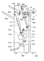
図1は本実施形態に係るシート処理装置と画像形成装置とからなる画像形成システムを概略的に示す図である。シート処理装置200は、画像形成装置100から搬送されてきたシートを受け取り、穿孔処理やスティプル処理等の後処理を行うもので、シート処理装置200内の入り口側には、画像形成装置100から搬送されてくるシートを受け取るために設けられた搬送姿勢補正機構である入口ローラ対2と、そこにシートをガイドする中継ガイド板4、入口ガイド板3が配置されている。搬送姿勢補正機構の出口側には、シートを穿孔するパンチユニット201が配置されている。
パンチユニット201の下方には、パンチかすを受けるパンチかすホッパ207が設けられている。パンチユニット201の出口側には、水平搬送路と上方搬送路202、下方搬送路210、211が設けられており、分岐爪208によってシートを分岐させている。
Embodiments of the present invention will be described with reference to the drawings.
FIG. 1 is a diagram schematically illustrating an image forming system including a sheet processing apparatus and an image forming apparatus according to the present embodiment. The
Below the
水平搬送路の出口側には排紙コロ205が設けられ、排紙コロ205から送り出されたシートは、トレイ206に積載される。下方搬送路210、211には、シートをスティプルトレイ213に送り出す紙送りローラ209、212が設けられている。端綴じの場合、1枚づつスティプルトレイ213に送り込まれたシートはシートの搬送方向に直交する方向の揃えをジョガー214によって行った後、所定枚数まとめられてスティプラユニット217によってステープル綴じの処理が施された後、放出爪215によってステープルトレイ213から排紙コロ205に送り出される。上方搬送路202を通ったシートは上トレイに積載される。中綴じの場合には、スティプルトレイ213で所定枚数のシートを揃えた後、束搬送ローラ対216により下方へ束搬送され、中綴じ位置でステイプラユニット217により綴じ処理が行われる。そして中綴じ処理が終了すると、束搬送ローラ対221により折り位置まで搬送され、折りプレート218と折りローラ219によって中折り処理がなされ、中折り排紙ローラによって中折り排紙トレイ220に排紙され、積載される。上述の構成はシート処理装置として公知であり、詳細な説明は省略する。本発明は、上記構成により、シート搬送姿勢補正を確実に行い、システムの小型化を達成できる。
A
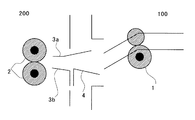
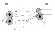
図2、3は図1の画像形成装置100とシート処理装置200のシート受け渡し部の拡大図である。ガイド板の上側を一体にし、入口ガイド板3aとし、下側は入口ガイド板3bと中継ガイド板4からなり、中継ガイド板4を入口ガイド板3aより突出させる。また、画像形成装置100の排紙コロ1から送り出されたシートaを中継ガイド板4に当たるように画像形成装置の紙送り部を上から下へ配置する。突き当たる方向は、特に限定されないが、図3のように画像形成装置から排紙されたシートの経路を下向きにして、ガイド板に突き当たることが、好ましい。
これにより、シート処理装置の入口ローラから画像形成装置の排紙口までの距離を短くしてシート処理装置の小型化が可能となり、かつ、シートの搬送姿勢の補正を確実にすることができる。また、入口ガイド板の強度と取り付け性を確保し、取り付ける画像形成装置の変更にあわせ、中継ガイド板のみ変更して対応することができる。さらに、2部材のガイド板の片方のみ歪むようにし、他物体との衝突時の損失を最小限に押えることができる。
2 and 3 are enlarged views of the sheet delivery unit of the
As a result, the distance from the entrance roller of the sheet processing apparatus to the discharge port of the image forming apparatus can be shortened, and the sheet processing apparatus can be downsized, and the correction of the sheet conveying posture can be ensured. Further, it is possible to ensure the strength and attachability of the entrance guide plate, and change only the relay guide plate according to the change of the image forming apparatus to be attached. Further, only one of the two member guide plates is distorted, and loss at the time of collision with another object can be minimized.
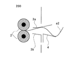
図4は、一体にしていないガイド板に突き当てた場合を示した図である。図5は、一体になっているガイド板に突き当てた場合を示した図である。本発明は、画像形成装置から排紙されたシートが、入口ガイド板と中継ガイド板を一体にしていないガイド板に突き当たるようにすることによって、シートを突き当てた際、1部材の方にシートを撓ませる(図4参照)。これにより、シートを突き当てた際一部材の方にシートを撓ませ、シートの搬送姿勢の補正時にシートへダメージを与えないようにすることができる。
逆に撓むと空間が充分でないため、撓むときにシートが当接して撓みにくくなり(図5参照)、入口ガイド板と中継ガイド板間にシートが詰まってしまったり、シートにダメージを与えてしまったり、シート先端が均一に搬送ローラに突き当たらなくなってしまう。
FIG. 4 is a diagram illustrating a case where the guide plate is abutted against a non-integrated guide plate. FIG. 5 is a view showing a case where the guide plate is abutted against the integrated guide plate. According to the present invention, when a sheet ejected from the image forming apparatus abuts against a guide plate in which the entrance guide plate and the relay guide plate are not integrated, the sheet is placed toward one member. Is bent (see FIG. 4). Accordingly, the sheet can be bent toward one member when the sheet is abutted, and the sheet can be prevented from being damaged when the conveyance posture of the sheet is corrected.
On the other hand, if the sheet is bent, the space is not enough, and when bent, the sheet will come into contact and become difficult to bend (see FIG. 5), the sheet will be clogged between the entrance guide plate and the relay guide plate, or the sheet may be damaged. If the sheet ends are not evenly bumped against the conveying roller, the sheet will not be able to be removed.
1 排紙コロ
2 入口ローラ対
3 入口ガイド板
3a 入口ガイド板
3b 入口ガイド板
4 中継ガイド板
100 画像形成装置
200 シート処理装置
201 パンチユニット
202 上方搬送路
205 排紙コロ
206 トレイ
207 パンチかすホッパ
208 分岐爪
209 紙送りローラ
210 下方搬送路
211 下方搬送路
212 紙送りローラ
213 スティプルトレイ
214 ジョガー
215 放出爪
216 束搬送ローラ対
217 ステイプラユニット
218 折りプレート
219 折りローラ
220 中折り排紙トレイ
221 束搬送ローラ対
a シート
DESCRIPTION OF
Claims (5)
前記シート処理装置は、ガイド板が、上下に備えられた入口ガイド板の少なくとも一方と、中継ガイド板と、を一体としている
ことを特徴とするシート処理装置。 In a sheet processing apparatus that performs one or more processes selected from stipple, sorting, and punching on a sheet imaged by an image forming apparatus,
The sheet processing apparatus is characterized in that the guide plate integrates at least one of the inlet guide plates provided at the top and bottom with the relay guide plate.
前記シート処理装置は、
一体となっていないガイド板が、入口ガイド板と中継ガイド板の2部材で形成される
ことを特徴とするシート処理装置。 The sheet processing apparatus according to claim 1,
The sheet processing apparatus includes:
A sheet processing apparatus, wherein the guide plate that is not integrated is formed of two members, an inlet guide plate and a relay guide plate.
前記シート処理装置は、入口ガイド板と中継ガイド板を一体となっていないガイド板が、一体となっているガイド板より突出している
ことを特徴とするシート処理装置。 The sheet processing apparatus according to claim 2,
In the sheet processing apparatus, a guide plate in which the entrance guide plate and the relay guide plate are not integrated protrudes from the integrated guide plate.
前記シート処理装置は、画像形成装置から排紙されたシートが、入口ガイド板と中継ガイド板を一体となっていないガイド板に突き当たるようにした
ことを特徴とするシート処理装置。 In the sheet processing apparatus according to any one of claims 1 to 3,
The sheet processing apparatus is characterized in that the sheet discharged from the image forming apparatus abuts against a guide plate in which the entrance guide plate and the relay guide plate are not integrated.
Priority Applications (1)
| Application Number | Priority Date | Filing Date | Title |
|---|---|---|---|
| JP2005364737A JP4969845B2 (en) | 2005-12-19 | 2005-12-19 | Image forming system |
Applications Claiming Priority (1)
| Application Number | Priority Date | Filing Date | Title |
|---|---|---|---|
| JP2005364737A JP4969845B2 (en) | 2005-12-19 | 2005-12-19 | Image forming system |
Publications (2)
| Publication Number | Publication Date |
|---|---|
| JP2007168917A true JP2007168917A (en) | 2007-07-05 |
| JP4969845B2 JP4969845B2 (en) | 2012-07-04 |
Family
ID=38296014
Family Applications (1)
| Application Number | Title | Priority Date | Filing Date |
|---|---|---|---|
| JP2005364737A Expired - Fee Related JP4969845B2 (en) | 2005-12-19 | 2005-12-19 | Image forming system |
Country Status (1)
| Country | Link |
|---|---|
| JP (1) | JP4969845B2 (en) |
Cited By (1)
| Publication number | Priority date | Publication date | Assignee | Title |
|---|---|---|---|---|
| JP2013184777A (en) * | 2012-03-07 | 2013-09-19 | Ricoh Co Ltd | Sheet postprocessing device and image forming device |
Citations (4)
| Publication number | Priority date | Publication date | Assignee | Title |
|---|---|---|---|---|
| JPH08169149A (en) * | 1994-12-19 | 1996-07-02 | Star Micronics Co Ltd | Paper ejection device |
| JPH10157918A (en) * | 1996-11-29 | 1998-06-16 | Ricoh Co Ltd | Seat storage device |
| JP2002120962A (en) * | 2000-10-13 | 2002-04-23 | Fuji Xerox Co Ltd | Sheet delivery device and sheet receiving device |
| JP2002128319A (en) * | 2000-10-20 | 2002-05-09 | Ricoh Co Ltd | Image forming system |
-
2005
- 2005-12-19 JP JP2005364737A patent/JP4969845B2/en not_active Expired - Fee Related
Patent Citations (4)
| Publication number | Priority date | Publication date | Assignee | Title |
|---|---|---|---|---|
| JPH08169149A (en) * | 1994-12-19 | 1996-07-02 | Star Micronics Co Ltd | Paper ejection device |
| JPH10157918A (en) * | 1996-11-29 | 1998-06-16 | Ricoh Co Ltd | Seat storage device |
| JP2002120962A (en) * | 2000-10-13 | 2002-04-23 | Fuji Xerox Co Ltd | Sheet delivery device and sheet receiving device |
| JP2002128319A (en) * | 2000-10-20 | 2002-05-09 | Ricoh Co Ltd | Image forming system |
Cited By (1)
| Publication number | Priority date | Publication date | Assignee | Title |
|---|---|---|---|---|
| JP2013184777A (en) * | 2012-03-07 | 2013-09-19 | Ricoh Co Ltd | Sheet postprocessing device and image forming device |
Also Published As
| Publication number | Publication date |
|---|---|
| JP4969845B2 (en) | 2012-07-04 |
Similar Documents
| Publication | Publication Date | Title |
|---|---|---|
| CN110282467B (en) | Sheet processing apparatus and image forming system | |
| JP7052565B2 (en) | Sheet post-processing device and image forming system equipped with it | |
| CN106516851B (en) | Sheet handling device | |
| JP5207851B2 (en) | Sheet stacking apparatus and image forming apparatus | |
| JP4518925B2 (en) | Paper post-processing device | |
| JP4969845B2 (en) | Image forming system | |
| JP2010018439A (en) | Sheet conveyance device, sheet post-processing device and sheet conveyance method | |
| JP6771286B2 (en) | Bookbinding device | |
| JP7127401B2 (en) | SHEET FOLDING DEVICE, SHEET POST-PROCESSING DEVICE AND IMAGE FORMING SYSTEM | |
| JP4513694B2 (en) | Image forming system | |
| JP2010208766A (en) | Sheet folding processing device, image forming device and image forming system | |
| JP4946478B2 (en) | Paper post-processing device | |
| JPH11171395A (en) | Paper post-processing equipment | |
| JP4315437B2 (en) | Paper folding device | |
| JP5233680B2 (en) | Post-processing apparatus and image forming system | |
| JP2009292603A (en) | Paper postprocessing device, and image forming device equipped with the same | |
| CN101219615A (en) | Paper post-processing device | |
| JP2003231092A (en) | Paper processing apparatus and image forming system | |
| JP3950723B2 (en) | Paper processing apparatus and image forming system | |
| JP4842725B2 (en) | Sheet processing apparatus and image forming apparatus | |
| US12415693B2 (en) | Sheet conveyance apparatus and image forming apparatus including the same | |
| JP2009073636A (en) | Paper transport device, paper processing device, image forming device, and image forming system | |
| JP3928501B2 (en) | Seat handling system | |
| JP5268582B2 (en) | Sheet stacking apparatus and image forming apparatus | |
| JP4897591B2 (en) | Paper insertion device |
Legal Events
| Date | Code | Title | Description |
|---|---|---|---|
| A621 | Written request for application examination |
Free format text: JAPANESE INTERMEDIATE CODE: A621 Effective date: 20081024 |
|
| A977 | Report on retrieval |
Free format text: JAPANESE INTERMEDIATE CODE: A971007 Effective date: 20100604 |
|
| A131 | Notification of reasons for refusal |
Free format text: JAPANESE INTERMEDIATE CODE: A131 Effective date: 20100727 |
|
| A521 | Written amendment |
Free format text: JAPANESE INTERMEDIATE CODE: A523 Effective date: 20100921 |
|
| A131 | Notification of reasons for refusal |
Free format text: JAPANESE INTERMEDIATE CODE: A131 Effective date: 20110215 |
|
| A521 | Written amendment |
Free format text: JAPANESE INTERMEDIATE CODE: A523 Effective date: 20110411 |
|
| A131 | Notification of reasons for refusal |
Free format text: JAPANESE INTERMEDIATE CODE: A131 Effective date: 20110906 |
|
| A521 | Written amendment |
Free format text: JAPANESE INTERMEDIATE CODE: A523 Effective date: 20111104 |
|
| TRDD | Decision of grant or rejection written | ||
| A01 | Written decision to grant a patent or to grant a registration (utility model) |
Free format text: JAPANESE INTERMEDIATE CODE: A01 Effective date: 20120403 |
|
| A01 | Written decision to grant a patent or to grant a registration (utility model) |
Free format text: JAPANESE INTERMEDIATE CODE: A01 |
|
| A61 | First payment of annual fees (during grant procedure) |
Free format text: JAPANESE INTERMEDIATE CODE: A61 Effective date: 20120404 |
|
| FPAY | Renewal fee payment (event date is renewal date of database) |
Free format text: PAYMENT UNTIL: 20150413 Year of fee payment: 3 |
|
| R150 | Certificate of patent or registration of utility model |
Ref document number: 4969845 Country of ref document: JP Free format text: JAPANESE INTERMEDIATE CODE: R150 Free format text: JAPANESE INTERMEDIATE CODE: R150 |
|
| LAPS | Cancellation because of no payment of annual fees |