JP2007184111A - Fuel cell system - Google Patents
Fuel cell system Download PDFInfo
- Publication number
- JP2007184111A JP2007184111A JP2005380613A JP2005380613A JP2007184111A JP 2007184111 A JP2007184111 A JP 2007184111A JP 2005380613 A JP2005380613 A JP 2005380613A JP 2005380613 A JP2005380613 A JP 2005380613A JP 2007184111 A JP2007184111 A JP 2007184111A
- Authority
- JP
- Japan
- Prior art keywords
- fuel cell
- fuel
- cell stack
- air
- temperature
- Prior art date
- Legal status (The legal status is an assumption and is not a legal conclusion. Google has not performed a legal analysis and makes no representation as to the accuracy of the status listed.)
- Pending
Links
Images





Classifications
-
- Y—GENERAL TAGGING OF NEW TECHNOLOGICAL DEVELOPMENTS; GENERAL TAGGING OF CROSS-SECTIONAL TECHNOLOGIES SPANNING OVER SEVERAL SECTIONS OF THE IPC; TECHNICAL SUBJECTS COVERED BY FORMER USPC CROSS-REFERENCE ART COLLECTIONS [XRACs] AND DIGESTS
- Y02—TECHNOLOGIES OR APPLICATIONS FOR MITIGATION OR ADAPTATION AGAINST CLIMATE CHANGE
- Y02E—REDUCTION OF GREENHOUSE GAS [GHG] EMISSIONS, RELATED TO ENERGY GENERATION, TRANSMISSION OR DISTRIBUTION
- Y02E60/00—Enabling technologies; Technologies with a potential or indirect contribution to GHG emissions mitigation
- Y02E60/30—Hydrogen technology
- Y02E60/50—Fuel cells
Landscapes
- Fuel Cell (AREA)
Abstract
【課題】起動時のエネルギー効率が向上した燃料電池システムを提供する。
【解決手段】高温膜を用いた複数の燃料電池スタック100‐1〜4に、暖機のためのヒータを付設し、起動時に1の燃料電池スタック100‐1のみを補助電源の電力によって暖機し、稼動可能となった該燃料電池スタック100‐1を稼動させ、その出力によって、他の燃料電池スタック100‐2〜4をヒータで暖め、最終的に全ての燃料電池スタック100‐1〜4の暖機を完了する。
【選択図】図1A fuel cell system with improved energy efficiency at startup is provided.
A heater for warming up is attached to a plurality of fuel cell stacks 100-1 to 4 using a high-temperature membrane, and only one fuel cell stack 100-1 is warmed up by power of an auxiliary power source at startup. Then, the fuel cell stack 100-1 that has become operable is operated, and the other fuel cell stacks 100-2 to 100-4 are warmed by heaters according to the output, and finally all the fuel cell stacks 100-1 to 100-4 Complete the warm-up.
[Selection] Figure 1
Description
本発明は、燃料電池システムに係り、詳しくはヒータを用いて暖機を行う燃料電池システムに関する。 The present invention relates to a fuel cell system, and more particularly to a fuel cell system that warms up using a heater.
燃料電池は、水素と酸素との電気化学反応を利用して電力を発生させるものであり、例えば、固体高分子電解質型燃料電池では、基本単位となる単位セルとセパレータを交互に複数積層して燃料電池スタックが構成される。そして、単位セルは、電解質膜が一対の電極で挟まれた構成となっている。燃料電池では、水素及び空気(酸素)が供給されることにより、以下のような水素と酸素の電気化学反応が起こり電気エネルギーが発生する。
(水素極側)H2→2H++2e−
(酸素極側)2H++1/2O2+2e−→H2O
そして、燃料電池には、上記発電された電力を取り出すための集電板が、積層方向における両端に設けられている。この集電板で取り出された電力は、インバータを介して走行モータ等の負荷に供給され、あるいは図示しない2次電池の充電等に用いられる。
A fuel cell generates electric power using an electrochemical reaction between hydrogen and oxygen. For example, in a solid polymer electrolyte fuel cell, a plurality of unit cells and separators that are basic units are alternately stacked. A fuel cell stack is configured. The unit cell has a configuration in which an electrolyte membrane is sandwiched between a pair of electrodes. In the fuel cell, when hydrogen and air (oxygen) are supplied, the following electrochemical reaction between hydrogen and oxygen occurs, and electric energy is generated.
(Hydrogen electrode side) H 2 → 2H + + 2e −
(Oxygen electrode side) 2H + + 1 / 2O 2 + 2e − → H 2 O
The fuel cell is provided with current collector plates for taking out the generated power at both ends in the stacking direction. The electric power taken out by the current collector plate is supplied to a load such as a traveling motor through an inverter, or used for charging a secondary battery (not shown).
ところで、上記電気化学反応(発電反応)を行うためには、電解質膜の性質に応じて、最適な温度環境が必要になるが、発電反応によって生成される水を蒸発させ、燃料室内での生成水の滞留を防止するために、摂氏100度以上において反応効率が高い電解質膜が用いられることが検討されている。
一方、上記電解質膜を用いた燃料電池システムに低温域でガスを供給すると、電極構成成分が凝結した生成水に溶解し電極が劣化するといった問題あり、生成水が蒸発する温度以上で発電反応を効率良く行える高温電解質膜が用いられる。この場合、ガスを供給する前に、燃料電池を生成水が蒸発する100度以上に暖める必要があるが、そのためのエネルギーが必要とされるため、エネルギー効率が悪化するといった問題があった。 On the other hand, when gas is supplied to the fuel cell system using the above electrolyte membrane at a low temperature, there is a problem that the electrode constituents dissolve in the condensed water and the electrode deteriorates. A high-temperature electrolyte membrane that can be efficiently used is used. In this case, before supplying the gas, it is necessary to warm the fuel cell to 100 degrees or more at which the generated water evaporates. However, since energy is required for this purpose, there is a problem that energy efficiency is deteriorated.
本発明は、起動時のエネルギー効率が向上した燃料電池システムを提供することを目的とする。 An object of the present invention is to provide a fuel cell system with improved energy efficiency at startup.
以上のような問題を解決する本発明は、以下のような構成を有する。 The present invention for solving the above problems has the following configuration.
(1) 燃料ガスが流入される燃料室と、と酸化ガスが流入される酸化ガス室とを高温電解質膜を介して隣接させ、燃料ガスと酸化ガスとの反応により発電する燃料電池を複数積層した複数の燃料電池スタックと、
各燃料電池スタックの外側面をそれぞれ覆う断熱材と、
燃料電池スタック毎に設けられたヒータと、
前記燃料室に接続され、燃料ガスを供給する燃料供給手段と、
前記酸化ガス室に空気を供給する空気供給手段と、
各燃料電池スタックの温度を検出する温度センサと、
燃料電池で発電された電力を蓄える蓄電手段と、
前記ヒータのオン・オフと、前記燃料供給手段による燃料ガス供給の有無と、前記空気供給手段による空気供給の有無とを、前記燃料電池スタック毎に制御する制御手段とを備え、
起動時において、前記制御手段は、特定の燃料電池スタックのヒータと前記蓄電手段とを通電し、
前記温度センサの検出値に基づき、前記特定の燃料電池スタックの温度が発電可能温度に到達したか判断する判断手段と、
前記判断手段が発電可能温度に到達したと判断するまで、前記特定の燃料電池スタックへのみ空気と燃料ガスを供給する限定供給手段と、
前記特定の燃料電池スタックの発電した電力を他の燃料電池スタックのヒータへ供給する電力分配手段とを備えることを特徴とする燃料電池システム。
(1) A fuel chamber into which fuel gas is introduced and an oxidant gas chamber into which oxidant gas is introduced are adjacent to each other via a high-temperature electrolyte membrane, and a plurality of fuel cells that generate power by reaction between the fuel gas and oxidant gas are stacked. A plurality of fuel cell stacks,
Thermal insulation covering the outer surface of each fuel cell stack;
A heater provided for each fuel cell stack;
Fuel supply means connected to the fuel chamber for supplying fuel gas;
Air supply means for supplying air to the oxidizing gas chamber;
A temperature sensor for detecting the temperature of each fuel cell stack;
Power storage means for storing the power generated by the fuel cell;
Control means for controlling on / off of the heater, the presence or absence of fuel gas supply by the fuel supply means, and the presence or absence of air supply by the air supply means for each fuel cell stack;
At startup, the control means energizes a heater of a specific fuel cell stack and the power storage means,
Determining means for determining whether the temperature of the specific fuel cell stack has reached a power generation possible temperature based on a detection value of the temperature sensor;
Limited supply means for supplying air and fuel gas only to the specific fuel cell stack until the determination means determines that the power generation possible temperature has been reached;
A fuel cell system comprising: power distribution means for supplying electric power generated by the specific fuel cell stack to a heater of another fuel cell stack.
(2) 燃料電池スタックの温度に応じて、空気の供給量を調整する供給量調整手段を有する請求項1に記載の燃料電池システム。
(2) The fuel cell system according to
請求項1記載の発明によれば、起動時においては、複数ある燃料電池スタックの中から特定の燃料電池スタックを選択し、これをヒータで暖機するため、ヒータが消費する電力を低減させることができる。さらに、この特定の燃料電池スタックの暖機が終了し、発電を開始させた後、この燃料電池スタックからの電力を他の燃料電池スタックの暖機に用いることにより、補助電源や外部電源からの電力の供給を要しないので、補助電源等の電力消費を抑制できる。 According to the first aspect of the present invention, at the time of startup, a specific fuel cell stack is selected from a plurality of fuel cell stacks, and this is warmed up by the heater, so that the power consumed by the heater is reduced. Can do. Furthermore, after the warm-up of this specific fuel cell stack is completed and power generation is started, the power from this fuel cell stack is used for warm-up of other fuel cell stacks, so that the auxiliary power source and external power source can be used. Since power supply is not required, power consumption of an auxiliary power source or the like can be suppressed.
請求項2に記載の発明によれば、燃料電池スタックの温度を高くする場合には、供給する空気の量を減少させ、温度を低くする場合には、供給する空気の量を増加させる。このように、供給する空気の量を調節することにより、発電稼動中の燃料電池スタックの温度を調節することができ、ヒータなどの暖機用の装置を不要とすることができる。 According to the second aspect of the present invention, when the temperature of the fuel cell stack is increased, the amount of supplied air is decreased, and when the temperature is decreased, the amount of supplied air is increased. Thus, by adjusting the amount of air to be supplied, the temperature of the fuel cell stack during power generation operation can be adjusted, and a warming-up device such as a heater can be dispensed with.
以下、図面を参照して、本発明の実施の形態を詳細に説明する。
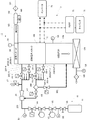
次にこの発明の好適実施形態について説明する。この実施形態は、電気自動車に搭載される燃料電池システムである。図1は、この発明の燃料電池システム1の構成を示すブロック図である。図1に示されているように、この燃料電池システム1は燃料電池スタック100と、水素貯蔵タンク11を含む燃料供給系10と、空気供給系12と、負荷系7とに大略構成される。
Hereinafter, embodiments of the present invention will be described in detail with reference to the drawings.
Next, a preferred embodiment of the present invention will be described. This embodiment is a fuel cell system mounted on an electric vehicle. FIG. 1 is a block diagram showing a configuration of a
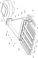
図2は、燃料電池スタック10の部分断面側面図、図3は、燃料電池スタックの部分断面斜視図である。
燃料電池スタック100は、単位セル2と、セパレータ3とを備えている。単位セル2は、空気極である酸素極21と燃料極22とで固体高分子電解質膜23を挟持した構成となっている。
2 is a partial sectional side view of the
The
固体高分子電解質膜23は、高温域でプロトン伝導度が十分に得られる高温膜が用いられる。すなわち、この高温膜は、雰囲気が高温・低湿度である場合において、プロトン伝導度が高い固体高分子電解質膜である。具体的に高温膜として用いられる材料としては、含フッ素系膜、炭化水素系膜、またはそれらの合成膜などのカチオン交換膜であり、低湿度で高いプロトン伝導性を示す特性の構造を持つもので構成される。低湿度で高いプロトン伝導性を示す特性とは、例えば、一般的な固体高分子電解質よりも水が十分に保水される材料か、又は水が無くてもプロトン伝導可能な物質が添加された材料であり、含フッ素系膜のパーフルオロ系膜ではスルホン酸基の濃度が高い(EW値が低い)ものであれば良く、炭化水素系膜のスルホン酸化ポリイミド膜では分子構造上に水を保持する物質であれば良い。
具体的なプロトン伝導度の一例を挙げると、温度が摂氏50〜140℃の範囲内で、湿度が0〜50%の雰囲気下において、一般的な固体高分子(摂氏50度以下、湿度50%以上の雰囲気下でプロトン伝導度が0.1S/cm以上)よりもプロトン伝導性が良好なものであり、例えば、摂氏120℃、湿度20%の雰囲気下において、プロトン伝導性が0.1S/cm以上であるものが好ましい。このような電解質を用いることで、電極や電解質の加湿が不要となり、加湿のための水供給装置を省略できる。
以上のような高温膜を用いることによって、発電反応によって発生する生成水が気化し、燃料ガスや酸化ガスとともに排出されるため、燃料電池スタック内に水が溜まることがなく、水排出のための構造を負荷する必要もなくなる。
As the solid
An example of a specific proton conductivity is a general solid polymer (less than 50 degrees Celsius, 50% humidity) in an atmosphere where the temperature is in the range of 50 to 140 degrees Celsius and the humidity is 0 to 50%. Proton conductivity is better than proton conductivity in the above atmosphere), for example, proton conductivity is 0.1 S / cm or more in an atmosphere of 120 degrees Celsius and 20% humidity. Are preferred. By using such an electrolyte, it is not necessary to humidify the electrode or the electrolyte, and a water supply device for humidification can be omitted.
By using the high-temperature membrane as described above, the generated water generated by the power generation reaction is vaporized and discharged together with the fuel gas and the oxidizing gas, so that water does not accumulate in the fuel cell stack, There is no need to load the structure.
セパレータ3は、酸素極21と燃料極22にそれぞれ接触して電流を取り出すための集電部材31と、集電部材31と単位セル2との間に介挿され、単位セル2の周端部に重ねられる介挿部材33とを有している。固体高分子電解質膜23において、燃料として供給された水素と酸化剤として供給された酸素が反応し、電力が得られるとともに、生成水が発生する。この電解質膜23は、生成水が蒸発する温度以上で発電反応を効率良く行える高温電解質膜であるため、その温度領域で発電反応を行うことで、生成水は水蒸気となり、燃料ガスや空気とともに、燃料電池スタック100の外部に排出される。
The
集電部材31は、導電性と耐蝕性を備えた材料で構成されている。集電部材31としては、例えば、カーボンや、金属等の材料で構成されている。金属で構成した場合には、例えば、ステンレス、ニッケル合金、チタン合金等の材料に耐蝕導電処理を施したものを用いることができる。ここで、耐蝕導電処理とは、例えば、金メッキ等が挙げられる。
The
集電部材31の、燃料極22に接触する面には、直線状に連続して隆起した凸部311が等間隔で複数形成され、該凸部311の間には、溝312がそれぞれ形成される。つまり、凸部311と溝312は、交互に配置された形状となっている。凸部311は、最も突出した峰の平面部が燃料極22に接触する接触部313となっており、この接触部313を介して燃料極22と通電可能となる。溝312と、燃料極22の表面とによって、燃料ガスとしての水素ガスが流通する燃料ガス流通路315が形成される。
On the surface of the current collecting
凸部311の両端(図中では上下端)には、凸部311に直交する方向に溝314、314が形成され、この溝314と燃料極22の表面とによって、燃料ガス流路316が形成される。複数の燃料ガス流通路315は、両端部で燃料ガス流路316にそれぞれ連通した構成となっており、複数の燃料ガス流通路315と一対の燃料ガス流路316とによって、燃料極22へ水素ガスを供給する燃料ガス保持部30が構成される。
燃料ガス保持部30には、燃料ガス供給孔318と燃料ガス排出孔317とが形成され、水素ガスは燃料ガス供給孔318から燃料ガス保持部30内に流入し、燃料極22に水素を供給しつつ、燃料ガス排出孔317から流出する。この実施形態では、集電部材31は、矩形であり、燃料ガス供給孔318と燃料ガス排出孔317は、相互に対向する位置(対角線方向)に、それぞれ配置されている。図2には、燃料ガス供給孔318が示されている。以上のように、燃料ガス保持部30は、各セパレータ3と単位セル2の間にそれぞれ形成されている。
A fuel
各燃料ガス保持部30の燃料ガス供給孔318は、燃料電池スタック100内の一方の端部において、集電部材31の積層方向に形成されている燃料ガス供給通路319aにそれぞれ連通しており、燃料ガス排出孔317は、燃料電池スタック100内の他方の端部において、集電部材31の積層方向に形成されている燃料ガス排出通路319bにそれぞれ連通している。燃料ガス供給通路319aと各燃料ガス供給孔318によって、燃料ガスを各燃料ガス保持部30に分配する燃料ガスマニホールドが構成される。燃料ガス供給通路319aは、燃料ガス供給流路201に接続され、燃料ガス排出通路319bはガス循環流路202に接続される。
The fuel
集電部材31の、酸素極21に接触する面には、直線状に連続して隆起した凸部321が等間隔で複数形成され、該凸部321の間には、溝322がそれぞれ形成される。つまり、凸部321と溝322は、交互に配置された形状となっている。凸部321は、最も突出した峰の平面部が酸素極21に接触する接触部323となっており、この接触部323を介して酸素極21と通電可能となる。溝322と、酸素極21の表面とによって、酸化ガスとしての空気が流通する空気流通路325が形成される。溝322は、集電部材31の両端部に達しており、空気流通路325の上下端は、燃料電池スタック100の外側に連通する開口部と連通している。両端の開口部の一方は、空気が流入する空気流入部326を形成し、他方の開口部は、空気が流出する空気流出部327を形成している。空気流入部326から流入した空気は、空気流通路325において、酸素極22と接触し、酸素極に酸素を供給しつつ、空気流出部327へ導かれる。
On the surface of the current collecting
以上のように、単位セル2と、セパレータ3は交互に積層され、積層方向の端部には、それぞれ電極板が重ねられ、電極板には側方に突出した電極が35a、35bが設けられる。このように構成された燃料電池スタック100は、空気流入部326と空気流出部327が設けられた面を除く側面が、断熱材36により覆われ、断熱材36にヒータが埋め込まれている。
As described above, the
上記説明した燃料電池スタック100は、複数設けられ、図2及び図3に示されているように、単位セル2とセパレータ3の積層方向に連結される。本実施形態では、4つの燃料電池スタック100‐1〜4が積層方向に沿って密着して配列されており、各燃料電池スタック100‐1〜4の各燃料ガス供給通路319aには、それぞれ別個に燃料ガスが供給され、各燃料ガス排出通路319bには、それぞれ別々に排出路が接続される。そして、各燃料電池スタック100‐1〜4には、それぞれ独立して燃料ガスの供給を行うことが可能な構成となっている。さらに、各燃料電池スタック100‐1〜4には、温度センサS5がそれぞれ設けられている。この温度センサS5によって、各燃料電池スタック100-1〜4の温度を検出することができる。
A plurality of the fuel cell stacks 100 described above are provided and connected in the stacking direction of the
次に、図1に示されている燃料電池システムの空気供給系12について説明する。空気供給系12は、空気導入路123と、空気マニホールド54と、空気排出路である排気ダクト124とを備えている。空気導入路123には、フィルタ121、空気ファン122、空気入口温度センサS4、空気マニホールド54の順で流入方向に沿って設けられている。空気マニホールド54には、各燃料電池スタック100‐1〜4毎に、導かれた空気を分割して別々に供給する分配装置と、空気の流量を調整する流量調整装置が設けられている。空気マニホールド54を通過した空気は、燃料電池スタック100の各空気流入部326に分割して流入させる。
Next, the air supply system 12 of the fuel cell system shown in FIG. 1 will be described. The air supply system 12 includes an
上記空気供給系12の具体的構成は、以下のとおりである。図5は空気供給系12の構成を示す全体斜視図、図6は、同じく全体平面図である。既述の通り、空気供給系12は、導風路としての空気導入路123を内側に画成する導風管126を有し、導風管126の空気導入側端部の取入口126sには、送風手段としての空気ファン122(エアブロア)の送風口122eが接続されている。空気ファン122の吸引口には、エアフィルタ121が設けられ、吸引時に、粉塵等のゴミが除去される。空気ファン122は、回転翼(インペラー)を回転させることにより、送風する遠心ブロアであり、回転翼を回転させるためのモータM1が、回転翼の回転軸に接続されている。導風管126の取入口126sは、送風口122eと同じ形状に構成されている。
The specific configuration of the air supply system 12 is as follows. FIG. 5 is an overall perspective view showing the configuration of the air supply system 12, and FIG. 6 is an overall plan view. As described above, the air supply system 12 has the
導風管126の他端開口部126eは、空気マニホールド54の空気流入口541と同形状の扁平な矩形状に形成され、分配装置61に接続されている。空気マニホールド54は、空気流入部326の集合体である開口940の全面を覆って設けられている。
The other end opening 126 e of the
図5および図6に示されているように、空気マニホールド54内において、空気流入方向に平行に、換言すると空気流入部326の長辺に平行に配置された(単位セル2やセパレータ3の積層方向に直交する向きに配置された)分離板611が、燃料電池スタック100‐1〜4の配置方向に3枚配置されている。分離板611は、燃料電池スタック100‐1〜4の接触部分に対応する位置に設けられている。この3つの分離板611と空気マニホールド54とによって、各燃料電池スタック100‐1〜4へ、個別に空気流を導く分配流路610‐1〜4が形成される。分離板611と分配流路610‐1〜4によって分配装置61が構成される。
As shown in FIGS. 5 and 6, the
各分配流路610‐1〜4の空気流入口541側には、各分配流路610‐1〜4毎に流量調整装置62がそれぞれ設けられている。図7は、流量調整装置62の斜視図である。図7は、分配流路610‐1に設けられた単体の流量調整装置620−1を示すものである。空気流入口541内には、空気マニホールド54と、空気導入路123とを仕切る仕切り板540が設けられ、この仕切り板540には、各分配流路610‐1〜4毎に、通風孔621が形成されている。その通風孔621内には、板状の調整部材622が2枚収納されている。2枚の調整部材622、622は、同大、同形状に形成され、この2枚を組み合わせることによって、通風孔621を閉鎖できるように形成されている。各調整部材622、622は、上下端辺の中心線上に支持軸623a、623bを有し、通風孔621内において回動自在に支持されている。そして、調整部材622、622の仕切り板540に対する角度θが、90度である場合には全開状態、0度である場合が全閉状態となり、この角度θの大きさによって、各燃料電池スタック100‐1〜4に供給される空気の量を、各々別個に調整することが可能となる。
On the
一方の支持軸623bは、通風空間の外側に突出し、その突出端にはアーム624、624が一体回動可能に固定され、アーム624、624の先端には連結操作部材625が接続されている。この連結操作部材625の他方の端部には、この連結操作部材625を部材の軸方向へ往復移動させる駆動装置が設けられ、該駆動装置は、制御装置により駆動量が制御される。この駆動装置は、たとえばモータ、油圧または空圧シリンダなどが用いられる。以上のような流量調整は、各分配流路610‐1〜4毎に別個に実施することができる。
One
次に、燃料電池スタック100‐1〜4の下流側には、排気ダクト124が接続される。排気ダクト124は、燃料電池スタック100の空気流出部327に接続され、空気流出部327から流出した空気を合流させ、外部へ導流する。排気ダクト124には、吸熱用熱交換器126が接続され、熱が吸収された排気は、フィルタ125を介して外部に排出される。排出される空気の温度は、吸熱用熱交換器126の下流側に設けられた温度センサS6で検出される。
Next, the
燃料供給系10の構成について説明する。燃料ガスボンベである水素貯蔵タンク11には、燃料ガス供給流路201、を介して燃料電池スタック100のガス取入口201INに接続されている。燃料ガス供給流路201には、水素貯蔵タンク11側から順に、水素元開閉弁V0、一次センサS0、レギュレータV2、水素調圧弁V3、ガス供給弁V4、三次圧センサS1が設けられ、三次圧センサS1とガス取入口201INの間には、後述のガス循環流路202が合流するエゼクタ25が設けられている。
The configuration of the
燃料ガス供給流路201のガス取入口201IN側は、4つのスタック用供給路201-1〜4に分岐し、スタック用供給路201-1〜4は、各燃料電池スタック100‐1〜4のガス取入口201IN-1〜4に接続される。スタック用供給路201-1〜4には、スタック用供給弁V8-1〜4がそれぞれ設けられている。
The gas inlet 201IN side of the fuel
燃料電池スタック100のガス排出口202OUTには、ガス循環流路202の一端が接続され、その他端は、燃料ガス供給流路201のエゼクタ25に接続され、さらに、ガス循環流路202には、循環電磁弁V7が設けられている。ガス循環流路202と燃料ガス供給流路201で循環路が構成される。
One end of the
ガス循環流路202のガス排出口202OUT側は、4つのスタック用排出路202-1〜4に分岐し、スタック用排出路202-1〜4は、各燃料電池スタック100‐1〜4のガス排出口202OUT-1〜4に接続される。スタック用排出路202-1〜4には、スタック用排出弁V5-1〜4がそれぞれ設けられている。
The gas outlet 202OUT side of the
ガス循環流路202において、循環電磁弁V7とスタック用排出路202-1〜4の分岐との間には、ガス排出路203の一端がトラップ27を介して接続されている。ガス排出路203の他端は、後述する排気ダクトに接続され、さらにガス排出路203は、ガス排出電磁弁V6を備えている。
In the
燃料電池スタック100には、負荷系7が接続されており、燃料電池スタック100で出力される電力は、この負荷系7に供給される。燃料電池スタック100の電極は、配線71を介してインバータ73に接続され、インバータ73を介してモータ等の負荷に接続されている。また、インバータ73には、出力制御装置75を介して補助電源であるキャパシタ76が接続されている。
A load system 7 is connected to the
なお、4つの燃料電池スタック100‐1〜4には、図8に示されているように、それぞれリレーR1〜4がそれぞれ直列に接続され、各燃料電池スタック100‐1〜4相互では並列に接続されている。そして、並列に接続された燃料電池スタック100‐1〜4に対して、さらに補助電源76と負荷が並列に接続されている。また、補助電源76と並列接続された燃料電池スタック100‐1〜4との間には、リレーR0が接続されている。リレーR1〜4のいずれかがオンで、リレーR0がオン状態である場合には、燃料電池スタック100‐1〜4の出力は、負荷77および補助電源76に供給される。補助電源76は、例えば蓄電池などの二次電池やキャパシタで構成される。
As shown in FIG. 8, the relays R1 to R4 are respectively connected in series to the four fuel cell stacks 100-1 to 100-4, and the fuel cell stacks 100-1 to 100-4 are connected in parallel to each other. It is connected. An
図9は、負荷77の構成を示す回路図である。負荷77は、電気自動車の駆動モータMや、その他の空気ファン122のモータM1などの補機類、さらに、燃料電池スタック100‐1〜4を暖めるヒータ36-1〜4がそれぞれ並列に接続されている。また、各ヒータ36−1〜4には、リレーRH1〜4が直列に接続されている。さらに、モータMにリレーRM1が、モータM1にはリレーRFがそれぞれ直列に接続されている。
FIG. 9 is a circuit diagram showing a configuration of the
燃料電池システム1の制御装置には、各センサS0、S1、S4〜5の検出値が入力され、かつ、各電磁弁V2〜8、ファン122、暖機ヒータ36‐1〜4、流量調整装置、インバータ73、出力制御装置75、リレーR0〜4、RM1、RH1〜4、RFのオン/オフを制御する。この制御装置には、図示しないイグニッションスイッチが接続され、モータの駆動や停止の指示信号が入力される。
Detection values of the sensors S0, S1, and S4 to 5 are input to the control device of the
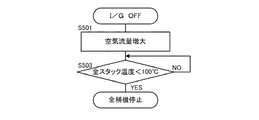
以上のように構成された燃料電池システム1の作用について説明する。図10は、イグニッションスイッチをオンにした場合の起動時の動作を示すフローチャート、図11〜13は定常運転時の動作を示すフローチャート、図14は、イグニッションスイッチをオフにした場合の動作を示すフローチャートである。
The operation of the
イグニッションスイッチをオンすると、燃料電池スタック100‐1のヒータ36−1をオンする(ステップS101)。これは、負荷77のリレーRH1をオンすることにより実行される。他のヒータ36−2〜4のリレーRH2〜4は、オフのままで維持される。このヒータに供給される電力は、補助電源76から供給される。他の燃料電池スタック100‐2〜4のヒータには、電力は供給されず、暖機は行われないため、補助電源76の蓄電量の消耗が抑制される。
When the ignition switch is turned on, the heater 36-1 of the fuel cell stack 100-1 is turned on (step S101). This is executed by turning on the relay RH1 of the
燃料電池スタック100‐1の温度を、燃料電池スタック100‐1に設けられた温度センサS5から検出し、その温度が摂氏100度を超えたか判断する(ステップS103)。超えていない場合には、先の処理に進まず、この処理を繰り返し実行する。摂氏100度を超えない場合には、発電反応を起こさせない。摂氏100度以下で発電反応を起こさせた場合には、生成水が発生し、電解質膜や電解質膜と電極との間にある反応層に含まれるリンが溶出し、性能を損なうためである。 The temperature of the fuel cell stack 100-1 is detected from a temperature sensor S5 provided in the fuel cell stack 100-1, and it is determined whether the temperature exceeds 100 degrees Celsius (step S103). If not, the process is repeatedly executed without proceeding to the previous process. If it does not exceed 100 degrees Celsius, no power generation reaction is caused. This is because when a power generation reaction is caused at 100 degrees Celsius or less, generated water is generated and phosphorus contained in the electrolyte membrane or the reaction layer between the electrolyte membrane and the electrode is eluted, thereby impairing the performance.
摂氏100度を超えた場合には、燃料電池スタック100‐1のリレーR1とリレーR0をオンに切り替える(ステップS105)。これにより、燃料電池スタック100‐1の出力が負荷77や補助電源76に供給できる状態となる。分配流路610‐1の流量調整装置620−1を開放し、他の流量調整装置620−2〜4は、閉じられている。このため、リレーRFをオンに切り換え、空気ファン122の駆動を開始し、空気の供給を開始すると(ステップS107)、空気の供給は、燃料電池スタック100‐1のみとなる。さらに、スタック用供給弁V8-1とスタック用排出弁V5−1を開放し、燃料電池スタック100‐1に水素ガスの供給を開始する(ステップS109)。
燃料電池スタック100‐2〜4のヒータをオンし(ステップS111)、ヒータへの電力は、燃料電池スタック100‐1の出力を供給する。これは、リレーRH2〜4をオンすることにより実施される。
When the temperature exceeds 100 degrees Celsius, the relay R1 and the relay R0 of the fuel cell stack 100-1 are switched on (step S105). As a result, the output of the fuel cell stack 100-1 can be supplied to the
The heaters of the fuel cell stacks 100-2 to 4-4 are turned on (step S111), and the power to the heater supplies the output of the fuel cell stack 100-1. This is implemented by turning on relays RH2-4.
燃料電池スタック100‐2〜4の温度をそれぞれ温度センサS5で検出し、その温度が摂氏100度を超えたか判断する(ステップS113)。超えていない場合には、先の処理に進まず、この処理を繰り返し実行する。超えた場合には、流量調整装置620−2〜4を開放し、燃料電池スタック100‐2〜4に空気の供給を開始する(ステップS115)。 The temperature of the fuel cell stacks 100-2 to 4 is detected by the temperature sensor S5, and it is determined whether the temperature exceeds 100 degrees Celsius (step S113). If not, the process is repeatedly executed without proceeding to the previous process. If exceeded, the flow control devices 620-2 to 620-4 are opened, and the supply of air to the fuel cell stacks 100-2 to 4 is started (step S115).
さらに、スタック用供給弁V8-2〜4とスタック用排出弁V5-2〜4とを開放し、各燃料電池スタック100‐2〜4に水素の供給を開始する(ステップS117)。これにより、全ての燃料電池スタック100‐1〜4において、発電反応が可能な状態となる。ステップS113〜S117の動作は、各燃料電池スタック100−2〜4毎に行われる。 Further, the stack supply valves V8-2 to V4-2 and the stack discharge valves V5-2 to 4 are opened, and supply of hydrogen to the fuel cell stacks 100-2 to 4 is started (step S117). Thereby, in all the fuel cell stacks 100-1 to 100-4, a power generation reaction is possible. The operations in steps S113 to S117 are performed for each fuel cell stack 100-2 to 4-4.
全ての燃料電池スタック100‐1〜4の温度が摂氏100度を超えたか判断する(ステップS119)。超えていない場合には、先の処理に進まず、この処理を繰り返し実行する。超えている場合には、燃料電池スタック100‐1〜4のヒータをオフに切り替え(ステップS111)、定常運転を開始する。 It is determined whether the temperatures of all the fuel cell stacks 100-1 to 100-4 have exceeded 100 degrees Celsius (step S119). If not, the process is repeatedly executed without proceeding to the previous process. When it exceeds, the heaters of the fuel cell stacks 100-1 to 4 are switched off (step S111), and the steady operation is started.
定常運転時には、温度センサS5によって、各燃料電池スタック100‐1〜4の温度を監視する(ステップS201)。そして、その温度が摂氏100度をより低くなった場合(ステップS203)と、摂氏200度を超えた場合(ステップS205)において、各燃料電池スタック100‐1〜4の温度が摂氏100〜200度の範囲となるように以下の動作を行う。 During steady operation, the temperature of each fuel cell stack 100-1 to 4 is monitored by the temperature sensor S5 (step S201). When the temperature becomes lower than 100 degrees Celsius (step S203) and exceeds 200 degrees Celsius (step S205), the temperature of each fuel cell stack 100-1 to 100 degrees Celsius is 100 to 200 degrees Celsius. The following operations are performed so that
燃料電池スタック100‐1〜4の温度が摂氏100度より低くなった場合には、流量調整装置620−1〜4によって、空気の供給量を減少させる(ステップS301)。外気温度は、燃料電池スタック100‐2〜4の温度よりも低いため、空気の流入を抑制することで、温度の低下を緩和する。また、暖めるために燃料電池スタック100‐1〜4のヒータをオンする(ステップS303)。そして、燃料電池スタック100‐1〜4の温度が摂氏100度を超えるか判断し(ステップS305)、超えた場合には、ヒータをオフする(ステップS307)。流量調整装置620−1〜4の空気流量を復帰させ(ステップS309)、定常運転に復帰させる(ステップS311)。 When the temperature of the fuel cell stacks 100-1 to 100-4 is lower than 100 degrees Celsius, the air supply amount is decreased by the flow rate adjusting devices 620-1 to 620-4 (step S301). Since the outside air temperature is lower than the temperature of the fuel cell stacks 100-2 to 100-4, the temperature drop is mitigated by suppressing the inflow of air. Further, the heaters of the fuel cell stacks 100-1 to 100-4 are turned on in order to warm them (step S303). Then, it is determined whether the temperature of the fuel cell stacks 100-1 to 100-4 exceeds 100 degrees Celsius (step S305), and if it exceeds, the heater is turned off (step S307). The air flow rate of the flow rate adjusting devices 620-1 to 620-4 is restored (step S309), and the steady operation is restored (step S311).
一方、燃料電池スタック100‐1〜4の温度が、摂氏200度を超えた場合には、空気ファン122の送風量を増大させる(ステップS401)。温度の低い外気の供給量が増加することで、過熱した燃料電池スタック100‐1〜4を冷やすことができる。燃料電池スタック100‐1〜4の温度が摂氏200度より低くなったか判断する(ステップS403)。低くなった場合には、空気流量を元の量に復帰させ(ステップS405)、定常運転に復帰させる(ステップS407)。このような空気流量の調整は、流量調整装置620−1〜4によって、各燃料電池スタック100‐1〜4毎に可能となっている。
On the other hand, when the temperature of the fuel cell stacks 100-1 to 100-4 exceeds 200 degrees Celsius, the air blowing amount of the
次に停止する場合の動作について説明する。イグニッションスイッチをオフにすると、水素ガスの供給を停止させ、空気ファン122の風量を増大させる(ステップS501)。水素ガスの供給がないため、発電反応は発生せず、外気の流入による冷却効果が得られる。全燃料電池スタック100‐1〜4の温度が摂氏100度より低くなったか判断し(ステップS503)、低くなった場合には、空気ファン122等の補機類を停止させる。
Next, the operation when stopping will be described. When the ignition switch is turned off, the supply of hydrogen gas is stopped and the air volume of the
以上のような構成のほか、燃料電池スタック100‐1〜4の接続は、図15に示されているように、直列接続であってもよい。この場合、燃料電池スタック100‐1と燃料電池スタック100‐2〜4の間にリレーR5が設けられ、燃料電池スタック100‐2〜4に並列にリレーR6が接続される。 In addition to the above configuration, the fuel cell stacks 100-1 to 100-4 may be connected in series as shown in FIG. In this case, a relay R5 is provided between the fuel cell stack 100-1 and the fuel cell stacks 100-2 to 4, and a relay R6 is connected to the fuel cell stacks 100-2 to 4 in parallel.
起動時において、燃料電池スタック100‐1が摂氏100度以上に温まった場合には、リレーR0とリレーR6がオン状態となり、燃料電池スタック100‐1の出力が負荷に供給される。この出力を用いて、燃料電池スタック100‐2〜4がヒータにより暖められ、摂氏100度を超えた場合に、リレーR6がオフとなり、リレーR5がオンされる。これにより、全燃料電池スタック100‐1〜4が直列に接続される。 When the fuel cell stack 100-1 is warmed to 100 degrees Celsius or more at startup, the relays R0 and R6 are turned on, and the output of the fuel cell stack 100-1 is supplied to the load. Using this output, when the fuel cell stacks 100-2 to 4-4 are warmed by the heater and exceed 100 degrees Celsius, the relay R6 is turned off and the relay R5 is turned on. Thereby, all the fuel cell stacks 100-1 to 100-4 are connected in series.
1 燃料電池システム
11 水素貯蔵タンク
100 燃料電池スタック
201、202 燃料ガス供給流路
DESCRIPTION OF
Claims (2)
各燃料電池スタックの外側面をそれぞれ覆う断熱材と、
燃料電池スタック毎に設けられたヒータと、
前記燃料室に接続され、燃料ガスを供給する燃料供給手段と、
前記酸化ガス室に空気を供給する空気供給手段と、
各燃料電池スタックの温度を検出する温度センサと、
燃料電池で発電された電力を蓄える蓄電手段と、
前記ヒータのオン・オフと、前記燃料供給手段による燃料ガス供給の有無と、前記空気供給手段による空気供給の有無とを、前記燃料電池スタック毎に制御する制御手段とを備え、
前記制御手段は、起動時において、特定の燃料電池スタックのヒータと前記蓄電手段とを通電し、
前記温度センサの検出値に基づき、前記特定の燃料電池スタックの温度が発電可能温度に到達したか判断する判断手段と、
前記判断手段が発電可能温度に到達したと判断するまで、前記特定の燃料電池スタックへのみ空気と燃料ガスを供給する限定供給手段と、
前記特定の燃料電池スタックの発電した電力を他の燃料電池スタックのヒータへ供給する電力分配手段とを備えることを特徴とする燃料電池システム。 A plurality of fuels in which a fuel chamber into which fuel gas is introduced and an oxidant gas chamber into which oxidant gas is introduced are adjacent to each other via a high-temperature electrolyte membrane and a plurality of fuel cells that generate power by reaction between the fuel gas and oxidant gas are stacked. A battery stack,
Thermal insulation covering the outer surface of each fuel cell stack;
A heater provided for each fuel cell stack;
Fuel supply means connected to the fuel chamber for supplying fuel gas;
Air supply means for supplying air to the oxidizing gas chamber;
A temperature sensor for detecting the temperature of each fuel cell stack;
Power storage means for storing the power generated by the fuel cell;
Control means for controlling on / off of the heater, the presence or absence of fuel gas supply by the fuel supply means, and the presence or absence of air supply by the air supply means for each fuel cell stack;
The control means energizes a heater of a specific fuel cell stack and the power storage means at startup,
Determining means for determining whether the temperature of the specific fuel cell stack has reached a power generation possible temperature based on a detection value of the temperature sensor;
Limited supply means for supplying air and fuel gas only to the specific fuel cell stack until the determination means determines that the power generation possible temperature has been reached;
A fuel cell system comprising: power distribution means for supplying electric power generated by the specific fuel cell stack to a heater of another fuel cell stack.
Priority Applications (1)
| Application Number | Priority Date | Filing Date | Title |
|---|---|---|---|
| JP2005380613A JP2007184111A (en) | 2005-12-29 | 2005-12-29 | Fuel cell system |
Applications Claiming Priority (1)
| Application Number | Priority Date | Filing Date | Title |
|---|---|---|---|
| JP2005380613A JP2007184111A (en) | 2005-12-29 | 2005-12-29 | Fuel cell system |
Publications (1)
| Publication Number | Publication Date |
|---|---|
| JP2007184111A true JP2007184111A (en) | 2007-07-19 |
Family
ID=38340022
Family Applications (1)
| Application Number | Title | Priority Date | Filing Date |
|---|---|---|---|
| JP2005380613A Pending JP2007184111A (en) | 2005-12-29 | 2005-12-29 | Fuel cell system |
Country Status (1)
| Country | Link |
|---|---|
| JP (1) | JP2007184111A (en) |
Cited By (5)
| Publication number | Priority date | Publication date | Assignee | Title |
|---|---|---|---|---|
| JP2011096600A (en) * | 2009-11-02 | 2011-05-12 | Gs Yuasa Corp | Fuel cell system, and operation method thereof |
| WO2012043645A1 (en) * | 2010-09-30 | 2012-04-05 | Toto株式会社 | Fuel cell device |
| JP2016518017A (en) * | 2013-05-15 | 2016-06-20 | インテリジェント エナジー リミテッドIntelligent Energy Limited | Cooling system for fuel cell |
| JP2022117829A (en) * | 2021-02-01 | 2022-08-12 | トヨタ自動車株式会社 | Fuel battery system |
| WO2024190752A1 (en) * | 2023-03-13 | 2024-09-19 | 株式会社アイシン | Fuel cell system |
Citations (4)
| Publication number | Priority date | Publication date | Assignee | Title |
|---|---|---|---|---|
| JPH0240865A (en) * | 1988-08-01 | 1990-02-09 | Hitachi Ltd | Temperature control device of fuel cell |
| JP2003234116A (en) * | 2002-02-07 | 2003-08-22 | Canon Inc | Fuel cell control method and control device |
| JP2004171823A (en) * | 2002-11-18 | 2004-06-17 | Honda Motor Co Ltd | Fuel cell stack and method for warming up the same |
| WO2005038973A1 (en) * | 2003-10-21 | 2005-04-28 | Alberta Research Council Inc. | Controlling solid oxide fuel cell operation |
-
2005
- 2005-12-29 JP JP2005380613A patent/JP2007184111A/en active Pending
Patent Citations (5)
| Publication number | Priority date | Publication date | Assignee | Title |
|---|---|---|---|---|
| JPH0240865A (en) * | 1988-08-01 | 1990-02-09 | Hitachi Ltd | Temperature control device of fuel cell |
| JP2003234116A (en) * | 2002-02-07 | 2003-08-22 | Canon Inc | Fuel cell control method and control device |
| JP2004171823A (en) * | 2002-11-18 | 2004-06-17 | Honda Motor Co Ltd | Fuel cell stack and method for warming up the same |
| WO2005038973A1 (en) * | 2003-10-21 | 2005-04-28 | Alberta Research Council Inc. | Controlling solid oxide fuel cell operation |
| JP2007509470A (en) * | 2003-10-21 | 2007-04-12 | アルバータ リサーチ カウンシル インコーポレイテッド | Operation control of solid oxide fuel cells |
Cited By (6)
| Publication number | Priority date | Publication date | Assignee | Title |
|---|---|---|---|---|
| JP2011096600A (en) * | 2009-11-02 | 2011-05-12 | Gs Yuasa Corp | Fuel cell system, and operation method thereof |
| WO2012043645A1 (en) * | 2010-09-30 | 2012-04-05 | Toto株式会社 | Fuel cell device |
| JP2016518017A (en) * | 2013-05-15 | 2016-06-20 | インテリジェント エナジー リミテッドIntelligent Energy Limited | Cooling system for fuel cell |
| JP2022117829A (en) * | 2021-02-01 | 2022-08-12 | トヨタ自動車株式会社 | Fuel battery system |
| JP7604920B2 (en) | 2021-02-01 | 2024-12-24 | トヨタ自動車株式会社 | Fuel Cell Systems |
| WO2024190752A1 (en) * | 2023-03-13 | 2024-09-19 | 株式会社アイシン | Fuel cell system |
Similar Documents
| Publication | Publication Date | Title |
|---|---|---|
| JP5318506B2 (en) | Fuel cell system | |
| JP2004030979A (en) | Fuel cell system | |
| US20180226667A1 (en) | Method for operating a fuel cell system and adjusting a relative humidity of a cathode operating gas during a heating phase | |
| US7306873B2 (en) | Method and apparatus for changing the direction of fluid flow in fuel cell flow fields | |
| JP2002093440A (en) | Solid polymer membrane fuel cell | |
| JP2007227209A (en) | Fuel cell system | |
| JP4453192B2 (en) | Polymer electrolyte fuel cell | |
| JP4465945B2 (en) | Fuel cell stack | |
| JP3677266B2 (en) | Fuel cell stack and its warm-up method | |
| JP4830852B2 (en) | Fuel cell system | |
| US7045235B2 (en) | Fuel cell system including air flow control | |
| JP2007184111A (en) | Fuel cell system | |
| JP3656596B2 (en) | Fuel cell system | |
| JP4556375B2 (en) | Fuel cell system | |
| JP2007087779A (en) | Fuel cell system | |
| JP2002075421A (en) | Humidifier for fuel cell | |
| JP3963368B2 (en) | Humidifier for fuel cell and heating method thereof | |
| JPH08306375A (en) | Polymer electrolyte fuel cell | |
| JP2008243540A (en) | Solid polymer electrolyte fuel cell power generator | |
| JP2009140614A (en) | Fuel cell | |
| WO2004042842A2 (en) | High temperature reactant recycling for pem fuel cell humidification | |
| JP2002015749A (en) | Fuel cell system | |
| JP2009238390A (en) | Fuel cell system | |
| JP2008108473A (en) | Humidification system for fuel cell | |
| JPH0927334A (en) | Solid polymer electrolyte membrane fuel cell and control method thereof |
Legal Events
| Date | Code | Title | Description |
|---|---|---|---|
| A621 | Written request for application examination |
Free format text: JAPANESE INTERMEDIATE CODE: A621 Effective date: 20080929 |
|
| A977 | Report on retrieval |
Free format text: JAPANESE INTERMEDIATE CODE: A971007 Effective date: 20111128 |
|
| A131 | Notification of reasons for refusal |
Free format text: JAPANESE INTERMEDIATE CODE: A131 Effective date: 20111130 |
|
| A02 | Decision of refusal |
Free format text: JAPANESE INTERMEDIATE CODE: A02 Effective date: 20120328 |