JP2007190847A - Printer - Google Patents
Printer Download PDFInfo
- Publication number
- JP2007190847A JP2007190847A JP2006012286A JP2006012286A JP2007190847A JP 2007190847 A JP2007190847 A JP 2007190847A JP 2006012286 A JP2006012286 A JP 2006012286A JP 2006012286 A JP2006012286 A JP 2006012286A JP 2007190847 A JP2007190847 A JP 2007190847A
- Authority
- JP
- Japan
- Prior art keywords
- paper
- printing
- paper jam
- hammer bank
- platen
- Prior art date
- Legal status (The legal status is an assumption and is not a legal conclusion. Google has not performed a legal analysis and makes no representation as to the accuracy of the status listed.)
- Granted
Links
Images
Landscapes
- Handling Of Sheets (AREA)
- Accessory Devices And Overall Control Thereof (AREA)
- Controlling Sheets Or Webs (AREA)
- Controlling Rewinding, Feeding, Winding, Or Abnormalities Of Webs (AREA)
Abstract
Description
本発明は、印刷装置に関し、特に、ドットラインプリンタの印刷媒体である印字用紙を搬送する際に発生する用紙ジャムの誤検出および未検出を防止する制御装置に関するものである。 The present invention relates to a printing apparatus, and more particularly, to a control apparatus that prevents erroneous detection and non-detection of a paper jam that occurs when a printing paper that is a printing medium of a dot line printer is conveyed.
ドットラインプリンタを用いて連続紙を印刷する場合、印刷用紙の仕様によっては用紙走行路の板金等との摩擦により印刷用紙が用紙走行経路の板金等に張り付いてしまい、適切に印刷用紙が搬送されず、用紙ジャムが発生する場合がある。そこで用紙ジャムを検出するために印刷用紙走行路中にセンサを設置して用紙の搬送が適切に行われているかを監視している。センサには反射式センサを使用し、連続紙の両端に用紙搬送用に設けてある孔にセンサ光が通過するように設置してセンサ信号を生成し、印刷制御部でセンサ信号の変化を確認していた。また、センサに等間隔にスリットの空いたローラーを挟んでこのローラーを印刷用紙に密着させ、用紙搬送時に回転することでセンサ信号を生成するという方法もある。 When printing continuous paper using a dot line printer, depending on the printing paper specifications, the printing paper may stick to the sheet metal in the paper path due to friction with the sheet metal in the paper path, etc. In some cases, a paper jam may occur. Therefore, in order to detect a paper jam, a sensor is installed in the printing paper traveling path to monitor whether the paper is properly conveyed. A reflective sensor is used as the sensor, and it is installed so that the sensor light passes through the holes provided for paper conveyance at both ends of the continuous paper to generate a sensor signal, and the change of the sensor signal is confirmed by the print control unit Was. Further, there is a method in which a sensor signal is generated by sandwiching a roller having slits at equal intervals between the sensor and the roller so that the roller is in close contact with the printing paper and rotating when the paper is conveyed.
生成されたセンサ信号は高速で往復運動しているシャトル機構部によって発生する振動が原因でノイズが生じてしまい、正常な信号とならず、印刷制御部は用紙ジャムを誤検出してしまったり、未検出でエラーと判断できない場合があった。 The generated sensor signal generates noise due to vibration generated by the shuttle mechanism that reciprocates at high speed, and it does not become a normal signal, and the print control unit erroneously detects paper jam, There were cases where it was not detected and an error could not be determined.
低コストが命題である低速ドットラインプリンタにおいて、いかなる部品においても安価な汎用品を用いることが重要である。これまで使用してきた用紙ジャムセンサは精度の高い反射式センサをドットラインプリンタ専用に加工したオリジナル部品を使用していた。 In a low-speed dot line printer where low cost is a proposition, it is important to use inexpensive general-purpose products for any part. The paper jam sensors that have been used so far have used original parts that have been processed exclusively for dot line printers by high-precision reflective sensors.
本発明が解決しようとする課題は、ドットラインプリンタにおいて安価な汎用品の透過式センサを使用することでコストダウンを実現し、用紙ジャムの検出を印刷モード毎に精度を高めることにある。 The problem to be solved by the present invention is to realize cost reduction by using an inexpensive general-purpose transmissive sensor in a dot line printer, and to improve the accuracy of paper jam detection for each printing mode.
本発明の請求項1記載の発明は、複数個の印字素子を搭載したハンマバンクと、前記ハンマバンクを桁方向に往復移動させるシャトル機構部と、ステッピングモータ等を用いて桁方向と垂直に印字用紙を間欠的に搬送するための紙送り機構部と、前記ハンマバンクの印字力を支持すると共に前記印字用紙のガイドとなるプラテンと、前記紙送り機構部の印字用紙搬送に同期して前記ハンマバンクとプラテンのギャップを広げ印字用紙搬送を容易にするプラテン機構部と、用紙ジャムを検出する用紙ジャム検出センサと、印字機構部を有するドットラインプリンタにおいて、前記用紙ジャム検出センサが出力する信号に印刷モード毎にフィルタリングの設定値を設定することを特徴とする。 According to the first aspect of the present invention, a hammer bank mounted with a plurality of printing elements, a shuttle mechanism for reciprocating the hammer bank in the digit direction, and printing in a direction perpendicular to the digit direction using a stepping motor or the like. A paper feed mechanism for intermittently conveying paper, a platen that supports the printing force of the hammer bank and serves as a guide for the print paper, and the hammer in synchronism with the print paper conveyance of the paper feed mechanism. In a dot line printer having a platen mechanism that widens the gap between the bank and the platen and facilitates printing paper conveyance, a paper jam detection sensor that detects paper jam, and a printing mechanism, the signal output by the paper jam detection sensor A filtering setting value is set for each print mode.
本発明の請求項2記載の発明は、請求項1記載の印刷装置において、前記印刷モード毎に設定する用紙ジャムセンサの出力する信号のフィルタリングの設定値を任意の紙送り量、および任意の時間によって変更可能とすることを特徴とする。 According to a second aspect of the present invention, in the printing apparatus according to the first aspect, the set value for filtering the signal output from the paper jam sensor set for each print mode is set to an arbitrary paper feed amount and an arbitrary time. It is possible to change by.
本発明の印刷装置によれば、シャトル機構部の高速往復動作によってノイズが生じた用紙ジャムセンサ信号を印刷モード毎に最適なフィルタリング設定値に設定することよって、振動等によって生じるノイズを削除することができ、用紙ジャムの誤検出および未検出が防止できる。 According to the printing apparatus of the present invention, by setting the paper jam sensor signal in which noise is generated by the high-speed reciprocating operation of the shuttle mechanism unit to the optimum filtering setting value for each printing mode, noise generated by vibration or the like is deleted. This can prevent erroneous detection and non-detection of paper jam.
本発明は、印刷制御用部に用紙ジャムセンサ信号用フィルタ回路、及びフィルタ設定回路の追加と、この回路を制御するソフトウェアの追加で実現した。 The present invention is realized by adding a paper jam sensor signal filter circuit and a filter setting circuit to the print control unit and software for controlling the circuit.
以下図面を参照して本発明を説明する。 The present invention will be described below with reference to the drawings.
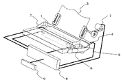
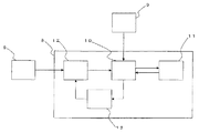
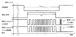
図1は、本発明の一実施例の印刷装置の概略図である。図2は、本発明の一実施例の印刷装置のブロック図である。図3は、本発明の一例となる印刷装置のタイミングチャートである。 FIG. 1 is a schematic diagram of a printing apparatus according to an embodiment of the present invention. FIG. 2 is a block diagram of a printing apparatus according to an embodiment of the present invention. FIG. 3 is a timing chart of the printing apparatus as an example of the present invention.
図1において、1はハンマバンク、2はインクリボン、3は印刷用紙、4はプラテン、5はシャトル機構部、6は用紙ジャムセンサ、7は紙送り機構部、8は印刷制御部、9は印刷モード設定手段である。 In FIG. 1, 1 is a hammer bank, 2 is an ink ribbon, 3 is printing paper, 4 is a platen, 5 is a shuttle mechanism, 6 is a paper jam sensor, 7 is a paper feed mechanism, 8 is a printing controller, and 9 is Print mode setting means.
印刷制御部8は印刷用紙3にハンマピンが複数個並んで配置されているハンマバンク1を印刷データから打ち出すハンマピンを指定し、ハンマバンク1を搭載しているシャトル機構部5を桁方向に往復運動させ、ハンマバンク1の打撃力を支持するプラテン4をインクリボン2と印刷用紙3との厚さに適したギャップに固定し、印刷動作を行う。ハンマバンク1の印刷終了後、紙送り機構部7によって水平方向に次の印刷位置まで紙送りを行い、印刷用紙3に密着するように設定されている用紙ジャムセンサ6のローラーが紙送り動作と同期して回転し、ローラーに刻まれたスリットをセンサが読み取り信号化して印刷制御部8へ入力する。印刷制御部8は前記センサ信号が変化しない場合に用紙ジャムを検出する。印刷用紙が次の印刷位置まで搬送されると印刷データの印刷を行う。以下同様に印刷動作、紙送り動作を繰り返し連続紙の印刷を行う。
The
図2において、6は用紙ジャムセンサ、8は印刷制御部、9は印刷モード設定手段、10はCPU、11は不揮発性素子、12はフィルタ回路、13はフィルタ設定回路である。 In FIG. 2, 6 is a paper jam sensor, 8 is a print control unit, 9 is a print mode setting means, 10 is a CPU, 11 is a non-volatile element, 12 is a filter circuit, and 13 is a filter setting circuit.
印刷制御部8は用紙ジャムセンサ6より入力される用紙ジャムセンサ信号を印刷制御部8内のCPU10で異常を監視している。フィルタ回路12は用紙ジャムセンサ信号のノイズを除去するための回路であり、任意の時間、および紙送り機構部7で駆動させているステッピングモータの任意のステップ数で設定が可変できるようになっている。印刷モード設定手段9より設定された印刷モードが印刷制御部8に入力されるとCPU10は印刷モード毎に不揮発性素子11に記憶されていた設定値をフィルタ設定回路13によってフィルタ回路12の設定を行う。
The
図3において、印刷信号はHレベルで印刷中、Lレベルで印刷待機中を示す。紙送り信号はHレベルで紙送り中、Lレベルで紙送り停止中を示す。用紙ジャムセンサ信号は印刷用紙3に密着させてある用紙ジャムセンサ6のローラが回転することでスリットがセンサを通過するため、図のような連続したパルスが印刷制御部8に入力される。
印刷用紙3を任意の数だけ紙送りを行う場合、紙送り動作中に印刷しないように紙送り印刷待機時間tPROFFと紙送り時間tPFはtPROFF>tPFとなるように印刷制御部8で制御されている。用紙ジャムセンサ信号は紙送り動作中でなければ信号レベルの変化は起こらないのであるが、シャトル機構部5の高速動作によって生ずる振動によって用紙ジャムセンサ6のローラーが動いてしまい、図のようなノイズがでてしまう場合がある。このノイズは印刷モード毎にシャトル機構部5の動作速度が異なるため、ノイズ幅も印刷モードによって異なる。この信号を除去するため、用紙ジャムセンサ信号を各印刷モード毎にフィルタ設定回路13によって最適値を設定したフィルタ回路12を通過させる。フィルタ回路12通過後の用紙ジャムセンサ信号はノイズのない用紙ジャムセンサ信号となるので精度のよい用紙ジャム検出を行うことができる。
In FIG. 3, the print signal indicates printing at H level and waiting for printing at L level. The paper feed signal indicates that the paper feed is at the H level and the paper feed is stopped at the L level. As the paper jam sensor signal is rotated by the roller of the paper jam sensor 6 that is in close contact with the printing paper 3, the slit passes through the sensor, so that continuous pulses as shown in FIG.
When an arbitrary number of paper sheets 3 are fed, the
更に、紙送り量によって紙送りの最高速度が異なる場合があり、この場合、用紙ジャムセンサ信号の幅も異なることから、紙送り量に応じてフィルタ設定値を変更することにより、振動により生じるノイズをより正確に除去することが可能となる。また、紙送り開始からの時間あるいは紙送り終了からの時間に応じてフィルタ設定値を変更することにより、紙送り中以外の用紙ジャムセンサ信号、すなわち振動により生じるノイズを的確に除去することができる。 In addition, the maximum paper feed speed may vary depending on the paper feed amount. In this case, the width of the paper jam sensor signal also differs. Therefore, by changing the filter setting value according to the paper feed amount, noise caused by vibrations Can be more accurately removed. Further, by changing the filter setting value according to the time from the start of paper feed or the time from the end of paper feed, it is possible to accurately remove paper jam sensor signals other than during paper feed, that is, noise caused by vibration. .
1はハンマバンク、2はインクリボン、3は印刷用紙、4はプラテン、5はシャトル機構部、6は用紙ジャムセンサ、7は紙送り機構部、8は印刷制御部、9は印刷モード設定手段、10はCPU、11は不揮発性素子、12はフィルタ回路、13はフィルタ設定回路である。
1 is a hammer bank, 2 is an ink ribbon, 3 is printing paper, 4 is a platen, 5 is a shuttle mechanism, 6 is a paper jam sensor, 7 is a paper feed mechanism, 8 is a printing controller, and 9 is a printing mode setting means.
Claims (2)
The printing apparatus according to claim 1, wherein a setting value for filtering a signal output from the paper jam sensor set for each printing mode can be changed by an arbitrary paper feed amount and an arbitrary time.
Priority Applications (1)
| Application Number | Priority Date | Filing Date | Title |
|---|---|---|---|
| JP2006012286A JP4802725B2 (en) | 2006-01-20 | 2006-01-20 | Printing device |
Applications Claiming Priority (1)
| Application Number | Priority Date | Filing Date | Title |
|---|---|---|---|
| JP2006012286A JP4802725B2 (en) | 2006-01-20 | 2006-01-20 | Printing device |
Publications (2)
| Publication Number | Publication Date |
|---|---|
| JP2007190847A true JP2007190847A (en) | 2007-08-02 |
| JP4802725B2 JP4802725B2 (en) | 2011-10-26 |
Family
ID=38446898
Family Applications (1)
| Application Number | Title | Priority Date | Filing Date |
|---|---|---|---|
| JP2006012286A Expired - Fee Related JP4802725B2 (en) | 2006-01-20 | 2006-01-20 | Printing device |
Country Status (1)
| Country | Link |
|---|---|
| JP (1) | JP4802725B2 (en) |
Citations (5)
| Publication number | Priority date | Publication date | Assignee | Title |
|---|---|---|---|---|
| JPS60220773A (en) * | 1984-04-17 | 1985-11-05 | Fujitsu Ltd | Printer |
| JPH02162069A (en) * | 1988-12-15 | 1990-06-21 | Fujitsu Ltd | Paper jam detector |
| JPH03130184A (en) * | 1989-10-17 | 1991-06-03 | Nec Eng Ltd | Jam detection system of serial printer |
| JP2002144653A (en) * | 2000-11-08 | 2002-05-22 | Fujitsu Ltd | Printing equipment |
| JP2003212387A (en) * | 2002-01-18 | 2003-07-30 | Seiko Epson Corp | Image forming device |
-
2006
- 2006-01-20 JP JP2006012286A patent/JP4802725B2/en not_active Expired - Fee Related
Patent Citations (5)
| Publication number | Priority date | Publication date | Assignee | Title |
|---|---|---|---|---|
| JPS60220773A (en) * | 1984-04-17 | 1985-11-05 | Fujitsu Ltd | Printer |
| JPH02162069A (en) * | 1988-12-15 | 1990-06-21 | Fujitsu Ltd | Paper jam detector |
| JPH03130184A (en) * | 1989-10-17 | 1991-06-03 | Nec Eng Ltd | Jam detection system of serial printer |
| JP2002144653A (en) * | 2000-11-08 | 2002-05-22 | Fujitsu Ltd | Printing equipment |
| JP2003212387A (en) * | 2002-01-18 | 2003-07-30 | Seiko Epson Corp | Image forming device |
Also Published As
| Publication number | Publication date |
|---|---|
| JP4802725B2 (en) | 2011-10-26 |
Similar Documents
| Publication | Publication Date | Title |
|---|---|---|
| CN108068476B (en) | Printing method | |
| EP2233304B1 (en) | Printing system and printing method | |
| JP2009226716A (en) | Image forming apparatus, cutting device, image forming system image forming program and cutting program | |
| JP2010036440A (en) | Reprinting controlling method of printer, and printer | |
| JP5225907B2 (en) | Printing system and printing apparatus | |
| JP6540387B2 (en) | Printing apparatus control method and printing apparatus | |
| JP5510211B2 (en) | Tandem printer | |
| US9120333B2 (en) | Printing apparatus and control method | |
| JP4802725B2 (en) | Printing device | |
| JP5239992B2 (en) | Conveyance error correction method in recording apparatus | |
| JP3928585B2 (en) | Print processing device | |
| JP5821441B2 (en) | Image forming apparatus | |
| JP4379443B2 (en) | Printer and printer control method | |
| JP5609999B2 (en) | Printer reprint control method and printer | |
| JP2004058337A (en) | Printer | |
| JP4798153B2 (en) | Sheet-like member cutting device | |
| JP4367467B2 (en) | Printer and printer control method | |
| JP2007296647A (en) | Stencil printing machine | |
| JP2012236380A (en) | Timing mark printing method, and continuous form processing device | |
| JP2012051266A (en) | Image recording apparatus and method for controlling the same | |
| JP2019123087A (en) | Printer, home positioning method, and program | |
| JP2007054962A (en) | Image forming apparatus control method and image forming apparatus | |
| JP6819494B2 (en) | Drilling device and image forming device | |
| JPH05138999A (en) | Sheet skew detection of printing device | |
| JP2012162051A (en) | Recorder and method of recording |
Legal Events
| Date | Code | Title | Description |
|---|---|---|---|
| RD02 | Notification of acceptance of power of attorney |
Free format text: JAPANESE INTERMEDIATE CODE: A7422 Effective date: 20081016 |
|
| A521 | Written amendment |
Free format text: JAPANESE INTERMEDIATE CODE: A821 Effective date: 20081016 |
|
| A621 | Written request for application examination |
Free format text: JAPANESE INTERMEDIATE CODE: A621 Effective date: 20081222 |
|
| A977 | Report on retrieval |
Free format text: JAPANESE INTERMEDIATE CODE: A971007 Effective date: 20101109 |
|
| A131 | Notification of reasons for refusal |
Free format text: JAPANESE INTERMEDIATE CODE: A131 Effective date: 20101116 |
|
| A521 | Written amendment |
Free format text: JAPANESE INTERMEDIATE CODE: A523 Effective date: 20110113 |
|
| TRDD | Decision of grant or rejection written | ||
| A01 | Written decision to grant a patent or to grant a registration (utility model) |
Free format text: JAPANESE INTERMEDIATE CODE: A01 Effective date: 20110712 |
|
| A01 | Written decision to grant a patent or to grant a registration (utility model) |
Free format text: JAPANESE INTERMEDIATE CODE: A01 |
|
| A61 | First payment of annual fees (during grant procedure) |
Free format text: JAPANESE INTERMEDIATE CODE: A61 Effective date: 20110725 |
|
| R150 | Certificate of patent or registration of utility model |
Ref document number: 4802725 Country of ref document: JP Free format text: JAPANESE INTERMEDIATE CODE: R150 Free format text: JAPANESE INTERMEDIATE CODE: R150 |
|
| FPAY | Renewal fee payment (event date is renewal date of database) |
Free format text: PAYMENT UNTIL: 20140819 Year of fee payment: 3 |
|
| S111 | Request for change of ownership or part of ownership |
Free format text: JAPANESE INTERMEDIATE CODE: R313113 |
|
| FPAY | Renewal fee payment (event date is renewal date of database) |
Free format text: PAYMENT UNTIL: 20140819 Year of fee payment: 3 |
|
| R350 | Written notification of registration of transfer |
Free format text: JAPANESE INTERMEDIATE CODE: R350 |
|
| LAPS | Cancellation because of no payment of annual fees |