JP2007190849A - Printer and print head - Google Patents
Printer and print head Download PDFInfo
- Publication number
- JP2007190849A JP2007190849A JP2006012288A JP2006012288A JP2007190849A JP 2007190849 A JP2007190849 A JP 2007190849A JP 2006012288 A JP2006012288 A JP 2006012288A JP 2006012288 A JP2006012288 A JP 2006012288A JP 2007190849 A JP2007190849 A JP 2007190849A
- Authority
- JP
- Japan
- Prior art keywords
- cap
- print head
- nozzle surface
- stopper
- capping mechanism
- Prior art date
- Legal status (The legal status is an assumption and is not a legal conclusion. Google has not performed a legal analysis and makes no representation as to the accuracy of the status listed.)
- Pending
Links
- 230000007246 mechanism Effects 0.000 claims abstract description 51
- 230000001105 regulatory effect Effects 0.000 claims abstract description 6
- 239000010410 layer Substances 0.000 description 19
- 238000010438 heat treatment Methods 0.000 description 9
- 238000007689 inspection Methods 0.000 description 6
- 238000012423 maintenance Methods 0.000 description 5
- 239000000463 material Substances 0.000 description 5
- 239000011347 resin Substances 0.000 description 5
- 229920005989 resin Polymers 0.000 description 5
- 239000000758 substrate Substances 0.000 description 4
- 239000002344 surface layer Substances 0.000 description 3
- 239000004743 Polypropylene Substances 0.000 description 2
- 230000002950 deficient Effects 0.000 description 2
- 238000007599 discharging Methods 0.000 description 2
- 238000001035 drying Methods 0.000 description 2
- 230000008531 maintenance mechanism Effects 0.000 description 2
- 238000012986 modification Methods 0.000 description 2
- 230000004048 modification Effects 0.000 description 2
- -1 polyethylene terephthalate Polymers 0.000 description 2
- 229920000139 polyethylene terephthalate Polymers 0.000 description 2
- 239000005020 polyethylene terephthalate Substances 0.000 description 2
- 229920000642 polymer Polymers 0.000 description 2
- 238000013459 approach Methods 0.000 description 1
- 238000007664 blowing Methods 0.000 description 1
- 239000011248 coating agent Substances 0.000 description 1
- 238000000576 coating method Methods 0.000 description 1
- 238000010586 diagram Methods 0.000 description 1
- 239000010419 fine particle Substances 0.000 description 1
- 230000017525 heat dissipation Effects 0.000 description 1
- 238000009413 insulation Methods 0.000 description 1
- 239000000155 melt Substances 0.000 description 1
- 230000015654 memory Effects 0.000 description 1
- 238000000034 method Methods 0.000 description 1
- 230000002093 peripheral effect Effects 0.000 description 1
- 239000000049 pigment Substances 0.000 description 1
- 229920001155 polypropylene Polymers 0.000 description 1
- 238000012545 processing Methods 0.000 description 1
- 230000000717 retained effect Effects 0.000 description 1
- 238000000926 separation method Methods 0.000 description 1
- 229920001169 thermoplastic Polymers 0.000 description 1
- 229920002803 thermoplastic polyurethane Polymers 0.000 description 1
- 238000012546 transfer Methods 0.000 description 1
Images

Landscapes
- Ink Jet (AREA)
Abstract
Description
本発明は、プリンタ及び印刷ヘッド装置、特にインクジェットプリンタ及びこのインクジェットプリンタに用いられる印刷ヘッド装置に関する。 The present invention relates to a printer and a print head device, and more particularly to an ink jet printer and a print head device used in the ink jet printer.
従来のインクジェットプリンタでは、印刷動作を終了した後、キャッピング機構により、キャップを複数のノズル孔が形成された印刷ヘッドのノズル面に密着させて、ノズル孔の乾燥を防止していた。通常、キャッピング機構は、印刷ヘッドの保守のためのメンテナンス機構に含まれる。 In the conventional inkjet printer, after the printing operation is finished, the cap is brought into close contact with the nozzle surface of the print head in which the plurality of nozzle holes are formed by the capping mechanism, thereby preventing the nozzle holes from drying. Normally, the capping mechanism is included in a maintenance mechanism for maintaining the print head.
このとき、キャップは、そのリップ(縁部)全体がノズル面に密着するように印刷ヘッドに圧接される。そのため、キャップを印刷ヘッドから離脱するときには、リップ全体が概略同時にノズル面から離隔されることになる。 At this time, the cap is pressed against the print head so that the entire lip (edge) is in close contact with the nozzle surface. Therefore, when the cap is removed from the print head, the entire lip is separated from the nozzle surface at substantially the same time.
この場合、ノズル面やキャップのリップに付着したインクが固化したり粘着化するので、ノズル面とキャップとが強固に接着されて、離脱できないことがある。そうすると、キャップの亀裂や、キャッピング機構自体の故障の原因となる。ノズル面から離脱しても、離脱する際の衝撃力が印刷ヘッドに作用し、周囲にインク滴が飛散し、装置を汚してしまうことがある。 In this case, the ink adhering to the nozzle surface and the lip of the cap solidifies or becomes sticky, so that the nozzle surface and the cap are firmly bonded and cannot be detached. If it does so, it will cause a crack of a cap and failure of the capping mechanism itself. Even when separated from the nozzle surface, the impact force at the time of separation may act on the print head, causing ink droplets to scatter around and contaminating the apparatus.
上記のような問題を回避するために、ノズル面やキャップに付着したインクを除去するための除去機構が必要である。そのため、メンテナンス機構が複雑で大型になるという問題があった。 In order to avoid the above problems, a removing mechanism for removing ink attached to the nozzle surface and the cap is necessary. Therefore, there is a problem that the maintenance mechanism is complicated and large.
本発明は、上記実状に鑑みてなされたもので、簡略な構成で小型化が可能であり、且つ確実にノズル面を保守することができるプリンタ及び印刷ヘッド装置を提供することを目的とする。 SUMMARY An advantage of some aspects of the invention is that it provides a printer and a print head device that can be downsized with a simple configuration and can reliably maintain a nozzle surface.
上記目的を達成するため、本発明の第1の観点に係るプリンタは、
印刷媒体を支持するプラテンと、
前記プラテンに対向して配置され、複数のノズル孔が配置されたノズル面を有し、前記複数のノズル孔からインクを吐出して前記印刷媒体に印刷する印刷ヘッドと、
前記印刷ヘッドの前記ノズル面に密着して該ノズル面を覆うキャップを保持するキャッピング機構と、
前記印刷ヘッドを移動する移動手段と、
を備え、
前記キャップが、前記移動手段による前記印刷ヘッドの移動に伴って前記ノズル面に接離する方向に移動し、
前記キャッピング機構は、前記キャップが前記印刷ヘッドの前記ノズル面から離脱するとき、前記キャップの少なくとも一端の動きを規制して、前記キャップを前記ノズル面に対して傾斜させる規制手段を有する、
ことを特徴とする。
In order to achieve the above object, a printer according to the first aspect of the present invention provides:
A platen that supports the print medium;
A print head that is disposed to face the platen, has a nozzle surface on which a plurality of nozzle holes are disposed, and discharges ink from the plurality of nozzle holes to print on the print medium;
A capping mechanism that holds a cap that closely contacts the nozzle surface of the print head and covers the nozzle surface;
Moving means for moving the print head;
With
The cap moves in a direction of contacting and separating from the nozzle surface with the movement of the print head by the moving means;
The capping mechanism has a restricting means for restricting movement of at least one end of the cap and tilting the cap with respect to the nozzle surface when the cap is detached from the nozzle surface of the print head.
It is characterized by that.
規制手段は、キャップの一端側に設けられた突起部に当接して、一端の動きを規制する一方のストッパと、キャップの他端側に設けられた突起部に当接して他端の動きを規制する他方のストッパとを有し、一方のストッパと他方のストッパとは、ノズル面からの距離が異なる位置で一端側の突起部と他端側の突起部に、それぞれ当接するように配置されていることが望ましい。 The restricting means abuts against a protrusion provided on one end of the cap and restricts the movement of one end, and a protrusion provided on the other end of the cap and moves the other end. One stopper and the other stopper are disposed so as to abut on the protrusion on one end and the protrusion on the other end, respectively, at different positions from the nozzle surface. It is desirable that
キャッピング機構は、キャップを保持する保持部材を有し、保持部材に、突起部をノズル面に接離する方向に沿って案内する案内溝が形成されたことが望ましい。 It is desirable that the capping mechanism has a holding member that holds the cap, and that the holding member is formed with a guide groove that guides the protrusion along the direction of contacting and separating the protrusion from the nozzle surface.
保持部材は、キャップを印刷ヘッドのノズル面に対して付勢する弾性部材を有することが望ましい。さらに、弾性部材は、ノズル面に接離する方向に沿って配置されたばね部材から構成されることが望ましい。 The holding member desirably has an elastic member that urges the cap against the nozzle surface of the print head. Furthermore, it is desirable that the elastic member is composed of a spring member arranged along a direction in which the elastic member is in contact with or away from the nozzle surface.
上記目的を達成するため、本発明の第2の観点に係る印刷ヘッド装置は、
プラテンに対向して配置され、複数のノズル孔が配置されたノズル面を有する印刷ヘッドと、
前記印刷ヘッドを収容する筐体と、
前記印刷ヘッドの前記ノズル面に密着して該ノズル面を覆うキャップを保持するキャッピング機構と、
前記印刷ヘッドを移動する移動手段と、
を備え、
前記キャップが、前記移動手段による前記印刷ヘッドの移動に伴って前記ノズル面に接離する方向に移動し、
前記キャッピング機構は、前記キャップが前記印刷ヘッドの前記ノズル面から離脱するとき、前記キャップの少なくとも一端の動きを規制して、前記キャップを前記ノズル面に対して傾斜させる規制手段を有する、
ことを特徴とする。
In order to achieve the above object, a print head device according to a second aspect of the present invention provides:
A print head disposed opposite to the platen and having a nozzle surface on which a plurality of nozzle holes are disposed;
A housing for accommodating the print head;
A capping mechanism that holds a cap that closely contacts the nozzle surface of the print head and covers the nozzle surface;
Moving means for moving the print head;
With
The cap moves in a direction of contacting and separating from the nozzle surface with the movement of the print head by the moving means;
The capping mechanism has a restricting means for restricting movement of at least one end of the cap and tilting the cap with respect to the nozzle surface when the cap is detached from the nozzle surface of the print head.
It is characterized by that.
規制手段は、キャップの一端側に設けられた突起部に当接して、一端の動きを規制する一方のストッパと、キャップの他端側に設けられた突起部に当接して他端の動きを規制する他方のストッパとを有し、一方のストッパと他方のストッパとは、ノズル面からの距離が異なる位置で一端側の突起部と他端側の突起部に、それぞれ当接するように配置されていることが望ましい。 The restricting means abuts against a protrusion provided on one end of the cap and restricts the movement of one end, and a protrusion provided on the other end of the cap and moves the other end. One stopper and the other stopper are disposed so as to abut on the protrusion on one end and the protrusion on the other end, respectively, at different positions from the nozzle surface. It is desirable that
キャッピング機構は、キャップを保持する保持部材を有し、保持部材に、突起部をノズル面に接離する方向に沿って案内する案内溝が形成されたことが望ましい。 It is desirable that the capping mechanism has a holding member that holds the cap, and that the holding member is formed with a guide groove that guides the protrusion along the direction of contacting and separating the protrusion from the nozzle surface.
保持部材は、キャップを印刷ヘッドのノズル面に対して付勢する弾性部材を有することが望ましい。さらに、弾性部材は、ノズル面に接離する方向に沿って配置されたばね部材から構成されることが望ましい。 The holding member desirably has an elastic member that urges the cap against the nozzle surface of the print head. Furthermore, it is desirable that the elastic member is composed of a spring member arranged along a direction in which the elastic member is in contact with or away from the nozzle surface.
筐体内には、キャッピング機構が収容されてもよい。 A capping mechanism may be accommodated in the housing.
筐体内には、移動手段が収容されてもよい。 A moving means may be accommodated in the housing.
本発明によれば、キャップが、ノズル面から離脱するとき、規制手段により、少なくとも一端の動きが規制されて、ノズル面に対して傾斜されるので、他の機構を追加することなく容易にキャップをノズル面から離脱することができ、装置の簡略化と小型化が可能であり、且つ確実にノズル面の保守をすることができる。 According to the present invention, when the cap is detached from the nozzle surface, the movement of at least one end is regulated by the regulating means, and the cap is inclined with respect to the nozzle surface. Therefore, the cap can be easily obtained without adding another mechanism. Can be detached from the nozzle surface, the apparatus can be simplified and miniaturized, and the nozzle surface can be reliably maintained.
本発明の実施の形態にかかるプリンタについて、以下図面を参照して説明する。 A printer according to an embodiment of the present invention will be described below with reference to the drawings.
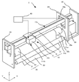
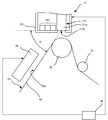
図1は、本発明の実施の形態に係るプリンタ1の部分的な斜視図であり、図2は、プリンタ1の概略断面図である。 FIG. 1 is a partial perspective view of a printer 1 according to an embodiment of the present invention, and FIG. 2 is a schematic cross-sectional view of the printer 1.
図1及び図2を参照して、プリンタ1は、印刷部10と、搬送装置20と、加熱部30とから構成される。
1 and 2, the printer 1 includes a
印刷部10は、印刷ヘッド装置11と、ホルダ16と、ホルダガイド17とを有する。
The
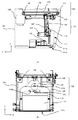
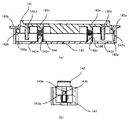
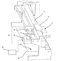
さらに図3に示すように、印刷ヘッド装置11は、印刷ヘッド111と、ヘッドキャリア112と、水平移動手段121と、垂直移動手段131と、キャッピング機構141と、筐体部151とを有する。図3(a)は、筐体151を図1に示すX方向から透視して印刷ヘッド装置11の内部構造を示してあり、図3(b)は、筐体151を図1に示すY方向から透視して印刷ヘッド装置11の内部構造を示してある。図1に示すX方向、Y方向、Z方向を以降の説明にも用いる。
Further, as shown in FIG. 3, the
印刷ヘッド111は、略直方体形状のヘッド部111aを有する。ヘッド部111aの下面(ノズル面)111bには、不図示のインクカートリッジから供給されたインクを吐出するノズル孔(不図示)が、ノズル面111bの長手方向に沿って所定の間隔で複数形成されている。
The
ヘッドキャリア112は、開口部112aが形成された板状部材である。ヘッドキャリア112は、印刷ヘッド111のノズル面111bを下方に向けて印刷ヘッド111をプラテンローラ22と対向するように保持する。
The
水平移動手段121は、水平ガイド軸122と、タイミングベルト123と、モータ124とを有する。
The horizontal moving
水平ガイド軸122は、Y方向(水平方向)に配置された棒部材である。
The
タイミングベルト123は、伸縮しない帯状部材である。タイミングベルト123は、一対のプーリー125に懸架される。
The
モータ124は、ステッピングモータである。モータ124は、一対のプーリー125のうち、一方のプーリー125を回転駆動してタイミングベルト123を駆動する。
The
垂直移動手段131は、枠体132と、垂直ガイド軸133と、カム134と、ベルト把持部135と、モータ136を有する。
The vertical moving
枠体132は、水平移動手段121の水平ガイド軸122にスライド可能に挿通される。枠体132は、ヘッドキャリア112を保持する。
The
垂直ガイド軸133は、枠体132にZ方向(垂直方向(印刷ヘッド111をキャッピング機構のキャップに接離する方向))に配置された棒部材である。
The
カム134は、一端にヘッドキャリア112の開口部112aに摺接する突出部134aが突設されている。カム134は、回転板137に固定されている。
One end of the
ベルト把持部135は、枠体132に固定されている。ベルト把持部135は、水平移動手段121のタイミングベルト123の一部を両側から把持し、タイミングベルト123の一部に固定されている。これにより、モータ124が駆動されてタイミングベルト123が回転駆動されることにより、垂直移動手段131が印刷ヘッド111と共に水平ガイド軸122に沿ってY方向へ移動されるようになっている。
The
モータ136は、ステッピングモータである。モータ136は、回転板137を回転させる。
The
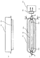
キャッピング機構141は、Y方向に印刷ヘッド111と隣接して配置される。図4、5及び6に示されるように、キャッピング機構141は、キャップ142と、キャップ142を保持するキャップホルダ143とを有する。
The
キャップ142は、ヘッド部111aのノズル面111bに密着してノズル面111bを覆うリップ142aがノズル面111bに対向するように周縁部に配置される。キャップ142の一端と他端には、それぞれ円筒形状の突起142bが一体に設けられている。
The
キャップホルダ143には、ノズル面111bと接離する方向に沿って案内溝143aが形成されている。案内溝143aには、キャップ142の突起142bが装着される。垂直移動手段131による印刷ヘッド111の移動に伴ってキャップ142がノズル面111bに接する方向に相対的に移動してノズル面111bに押圧されるとき、案内溝143aは、その下端までキャップ142をキャップホルダ143内で移動可能に案内する。
In the
キャップホルダ143には、弾性部材144が配置される。弾性部材144は、キャップ142がノズル面111bに接離する方向に沿って配置されたコイルばねから構成される。弾性部材144を構成するコイルばねには、その上端からキャップ142の突出部142cが挿入され、その下端からは、キャップホルダ143の突出部143cが挿入されている。弾性部材144は、キャップ142をノズル面111bに向けて付勢する。また、キャップ142には、ノズル面111bにキャップ142が被着されたときにキャップ142内の空気を抜くための管142dが設けられており、図示しないが、管142dにはポンプに連通するパイプが繋げられる。キャップホルダ143には、これらのパイプを通す穴143dが設けられている。
An
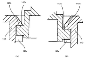
キャップホルダ143には、キャップ142の一端及び他端の突起142bの上端に当接してキャップ142の一端及び他端の動きを規制するストッパ145a,145bが形成されている。一端側のストッパ145aと他端側のストッパ145bとは、ノズル面111bからの距離が異なる位置でキャップ142の一端の突起142bと他端の突起142bとに、それぞれ当接するように配置される(図6参照)。そのため、キャップ142がノズル面111bに押圧されていない状態では、キャップ142は、弾性部材144によりノズル面111bに向けて付勢されて突起142bの上端がストッパ145a,145bに当接するので、ノズル面111bに対して傾斜される。
The
筐体部151は、印刷ヘッド111、水平移動手段121、垂直移動手段131、キャッピング機構141を収容する略直方体の部材である。筐体部151は、下面に、印刷ヘッド111のノズル面111bを露出する図示しない開口部を有する。
The
ホルダ16は、印刷ヘッド装置11を脱着可能に保持する。ホルダ16は、不図示のモータにより駆動されるベルト(不図示)に連結されて、ホルダガイド17に形成されたガイドレール17aに沿ってX方向に移動可能に構成されている。
The
ホルダガイド17は、X方向に延びた略直方体形状の部材である。ホルダガイド17の上面(Z方向)には、長手方向(X方向)に沿ってガイドレール17aが形成されている。ホルダガイド17は、地板24の窓部24aを貫通して、両端が地板23及び支持板25に固定されている。
The
搬送装置20は、送りローラ21と、プラテンローラ22とを有する。
The
送りローラ21は、軸21aと、円筒状の回転部21bとを有する。軸21aは、X方向に略水平に配置され、両端が、それぞれ地板23、24に固定されている。回転部21bは、固定された軸21aの周りに回転可能に配置される。
The
プラテンローラ22は、軸22aと、円筒状の回転部22bとを有する。軸22aは、X方向に略水平に配置され、両端が、それぞれ地板23、24に回転可能に支持される。軸22aの一端は、モータ26に接続される。
The
プラテンローラ22と図示しない引き取り機構とにより、印刷媒体50の送出側の搬送経路P1が形成される。この搬送経路P1の搬送面は、印刷ヘッド装置11のヘッド部111aのノズル面111bと角度αをなすように傾斜されて形成されている。
A transport path P1 on the delivery side of the
地板23,24は、軸21a,22aに直交するように、互いに平行に配置されている。
The ground planes 23 and 24 are arranged in parallel to each other so as to be orthogonal to the
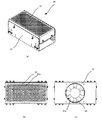
図7及び図8に示すように、加熱部30は、ケース31と、前面パネル32と、加熱器33と、ファン34とを有する。
As shown in FIGS. 7 and 8, the
ケース31は、前面パネル32と組み合わされて、加熱器33とファン34を収容する。ケース31のファン34が配置されている側には、空気を吸い込むための開口部31aが形成されている。
The
前面パネル32には、加熱器33により加熱された加熱空気を吹き出すための孔32aが複数形成されている。
The
加熱器33は、絶縁被覆された電気ヒータから構成される。加熱器33の外周には、放熱面積を増加させて熱伝達効率を上げるために、フィン33aが配置されている。加熱器33は、ファン34により供給された空気を加熱する。
The
ファン34は、加熱器33の前面パネル32から離間された側に配置される。ファン34は、ケース31の開口部31aから空気を吸引して、加熱器33に供給する。
The
再度図2を参照して述べると、加熱部30は、印刷ヘッド装置11のヘッド部111aのノズル面111bと角度αをなすように傾斜された送出側の搬送経路P1に沿って配置される。このとき、前面パネル32は、送出側の搬送経路P1に位置する印刷媒体50と所定の距離だけ隔てて平行に対向するように配置される。したがって、ファン34により吸引された空気は、加熱器33により加熱されて、前面パネル32の孔32aから、送出側の搬送経路P1に位置する印刷媒体50の印刷面50aに略垂直に供給される。
Referring again to FIG. 2, the
制御部40は、MPU(Micro Processor Unit)、各種メモリなどから構成される。制御部40は、印刷時には、不図示のモータを駆動して、印刷ヘッド装置11をX方向(プラテンローラ22の延伸方向)に移動させて所定の位置で停止させた後、モータ26を駆動してプラテンローラ22を回転させつつ印刷ヘッド111を駆動して、インクをノズルから吐出させる。制御部40は、印刷ヘッド装置11の水平移動手段121のモータ124と、垂直移動手段131のモータ136とを駆動して、ヘッドキャリア112に保持された印刷ヘッド111を印刷媒体50に印刷する印刷位置と、キャッピング機構141によりヘッド部111aのノズル面111bを清浄に保守するヘッドキャップ位置とに移動する。ヘッドキャップ位置では、キャッピング機構141のキャップ142が、ノズル面111bに押圧されて、リップ142aがノズル面111bに密着し、ノズル孔の乾燥を防止してインクの粘度の上昇による吐出不良を防止する。
The
印刷媒体50は、基材と、定着層とから構成される。
The
基材は、紙やPET(ポリエチレンテレフタレート)フィルムやPP(ポリプロピレン)から構成される。 The substrate is made of paper, PET (polyethylene terephthalate) film, or PP (polypropylene).
定着層は、ウレタン樹脂等の、吐出されたインクを吸収し、定着可能な材料から構成される。定着層は、基材の表側に積層して配置される。定着層は、加熱されると、吸収したインクを乾燥し昇華させてその色素を定着させる。 The fixing layer is made of a material that can absorb and fix the ejected ink, such as urethane resin. The fixing layer is laminated on the front side of the substrate. When the fixing layer is heated, the absorbed ink is dried and sublimated to fix the dye.
次に、プリンタ1の印刷動作について説明する。 Next, the printing operation of the printer 1 will be described.
プリンタ1の印刷前の待機状態では、図9(a)に示されるように印刷ヘッド111のノズル面111bにキャップ142が被着されている。
そして、図示しないボタンにより印刷が指示されると、制御部40は、垂直移動手段131のモータ136を駆動する。
In the standby state before printing by the printer 1, a
Then, when printing is instructed by a button (not shown), the
図3を参照して、モータ136は、回転板137を時計方向に回転させる。カム134も、回転板137の回転に伴って時計方向に回転する。このとき、カム134の突出部134aは、ヘッドキャリア112の開口部112aの縁に摺接しているので、カム134の回転に伴って、ヘッドキャリア112は、垂直ガイド軸133に沿ってZ方向に垂直に移動する。これにより、図9(a)に示すヘッドキャップ位置にある印刷ヘッド111がZ方向に上昇して、ヘッド部111aのノズル面111bからキャップ142が離脱される。
Referring to FIG. 3,
図9を参照してより詳細に述べると、ヘッド部111aのノズル面111bにキャップ142が被着されているときには、キャップ142は、弾性部材144の付勢力により均一にノズル面111bに押圧されている。このとき、キャップ142は、両端の突起142bの上端がストッパ145a,145bから離間して、ノズル面111bと平行にキャップホルダ143に保持される(図9(a))。
Referring to FIG. 9 in more detail, when the
そして、印刷ヘッド111の上昇に伴って、キャップ142は、ノズル面111bから離脱する方向に相対的に移動される。一端側のストッパ145aは、他端側のストッパ145bよりノズル面111bからの距離が大きくなる位置でキャップ142の一端の突起142bと当接するように配置されている。そのため、弾性部材144の付勢力により、一端の突起142bが案内溝143aに案内されてキャップホルダ143内を移動され、他端の突起142bより先に、ストッパ145aに当接する。そして、キャップ142の一端の動きはストッパ145aにより規制される一方、キャップ142の他端は、突起142bが案内溝143aに案内されて、キャップホルダ143内を移動する。すなわち、キャップ142は、ノズル面111bに対して傾き始め、キャップ142の一端側が他端側より先にノズル面111bから離れる(図9(b))。
As the
さらに、印刷ヘッドが上昇すると、弾性部材144の付勢力により、他端の突起142bも、ストッパ145bに当接するまで、案内溝143aに案内されてキャップホルダ143内を移動する。ストッパ145bに当接すると、キャップ142の他端は、その動きを規制される。したがって、キャップ142は、ノズル面111bに対して、一端側のストッパ145aと他端側のストッパ145bの突起142bに当接する位置の差に応じて傾斜され、傾斜した状態でノズル面111bから離脱する(図9(c))。
Further, when the print head is raised, the
次に、制御部40は、水平移動手段121のモータ124を駆動し、タイミングベルト123を反時計方向に回転駆動することで、印刷ヘッド111をプラテンローラ22に対向する退避位置まで移動する。
Next, the
続いて、垂直移動手段131のモータ136は、回転板137を反時計方向に回転させる。カム134も、回転板137の回転に伴って反時計方向に回転する。カム134の回転に伴って、ヘッドキャリア112は、垂直ガイド軸133に沿って下方(印刷ヘッド111がプラテンローラ22に接近する方向)に垂直に移動する。これにより、印刷ヘッド111をプラテンローラ22に対向する印刷位置に垂直に移動する。
Subsequently, the
印刷ヘッド111を印刷位置に移動した後、制御部40は、不図示のモータを駆動してプラテンローラ22を回転して印刷媒体50を搬送しつつ印刷ヘッド111を駆動してインクをノズルから吐出させる。これにより、印刷媒体50の印刷面50aに所望の文字等が所定のピッチで印刷される。
After moving the
そして、インクが吐出された印刷面50aが加熱部30と対向する位置に至ると、インクが吐出された印刷面50aが加熱部30で加熱される。
When the
このとき、制御部40は、加熱部30を制御して、前面パネル32に形成された孔32aから加熱空気を送出側の搬送経路P1に位置する印刷媒体50の印刷面50aに略垂直に供給し、インクが吐出された印刷面50aを所定の温度に加熱する。これにより、印刷媒体50の印刷面50aに吐出したインクを乾燥して定着させることができる。
At this time, the
印刷動作が終了すると、制御部40は、垂直移動手段131のモータ136を起動する。
When the printing operation is completed, the
垂直移動手段131のモータ136は、回転板137を時計方向に回転させる。カム134も、回転板137の回転に伴って時計方向に回転する。カム134の回転に伴って、ヘッドキャリア112は、上方(印刷ヘッド111がプラテンローラ22から離反する方向)に垂直に移動する。これにより、印刷ヘッド111を印刷位置から退避位置まで垂直に移動する。退避位置では、印刷ヘッド111は、キャッピング機構141の上端よりも上方に位置し、引き続く水平移動がキャッピング機構141により妨げられない。
The
続いて、制御部40は、水平移動手段121のモータ124を起動する。
Subsequently, the
水平移動手段121のモータ124は、タイミングベルト123を図3時計方向に駆動する。タイミングベルト123の駆動に伴って、垂直移動手段131の枠体132は、印刷ヘッド111と共に図3左方に水平に移動する。これにより、印刷ヘッド111を退避位置からキャッピング機構141に相対する位置まで移動する。
The
次に、垂直移動手段131のモータ136は、回転板137を反時計方向に回転させる。カム134も、回転板137の回転に伴って反時計方向に回転する。カム134の回転に伴って、ヘッドキャリア112は、下方に垂直に移動する。これにより、印刷ヘッド111を図9(a)に示すヘッドキャップ位置まで垂直に下方に移動し、キャップホルダ143が保持するキャップ142に当接して、キャップ142がヘッド部111aのノズル面111bに被着される。
Next, the
より詳細には、ヘッド部111aの下方への移動に伴って、キャップ142は、ノズル面111bに対して傾いた状態のまま、他端側がノズル面111bに接する(図9(b))。さらに、ヘッド部111aが移動すると、ヘッド部111aからの下方へ押す力によって、他端側の突起142bは、ストッパ145bから離れて、案内溝143aにその下端まで案内されてキャップホルダ143内を下方に移動する。そして、キャップ142がノズル面111bと平行になると、印刷ヘッド111の移動に伴って、一端側の突起142bも、ストッパ145aから離れ、案内溝143aにその下端まで案内されてキャップホルダ143内を下方に移動する。このようにして、キャップ142は、ノズル面111bに平行な状態で、弾性部材144の付勢力によりノズル面111bに対して均一に押圧されて、ノズル面111bに被着される(図9(a))。
More specifically, with the downward movement of the
ここで、図9(a)に示されるように、ヘッド部111aのノズル面111bにキャッピング機構141のキャップ142が被着されたプリンタ1の待機状態において、図示しないボタンによりメンテナンスが指示されると、制御部40は、キャッピング機構141の不図示のポンプを駆動してキャッピング機構141のキャップ142内の空気を抜くことで真空圧を作り、ヘッド部111aのインクを吸引し、ヘッド部111aのノズルの詰まりを取り除く。なお、メンテナンスの指示はボタン操作に限らず、所定数だけ待機状態とする度に行うなど適宜に設定してもよい。
Here, as shown in FIG. 9A, when maintenance is instructed by a button (not shown) in the standby state of the printer 1 in which the
以上説明したように、キャッピング機構141のキャップ142が、ノズル面111bから離脱するとき、規制手段としてのストッパ145a,145bにより、少なくとも一端の動きを規制されて、ノズル面111bに対して傾斜される。そのため、キャッピング中に、印刷ヘッド111のノズル面111bとキャップ142のリップ142aに付着したインクが固化したり粘着化しても、容易にノズル面111bから離脱することができる。したがって、他の機構を追加してノズル面111bやキャップ142に付着したインクを清掃する必要がなく、簡略な構成で小型化することが可能で、且つ確実にヘッド部111aのノズル面111bの保守をすることができる。
また、キャップ142の一端側が先にノズル面111bから離れ、次いで他端側がノズル面111bから離れてキャップ142全体がノズル面111bから離脱される。そのため、キャップ142の離脱の際に、印刷ヘッド111に加わる衝撃を減少できるので、印刷ヘッド111の周囲にインクが飛散して、装置を汚すことを防止する。
As described above, when the
In addition, one end side of the
本発明は、上記の実施の形態に限定されず、その応用及び変形等は任意である。 The present invention is not limited to the above-described embodiment, and its application and modification are arbitrary.
上記の実施の形態では、キャップ142の突起142bとそれぞれ当接してその動きを規制する一端側と他端側のストッパ145a,145bを配置した。しかし、少なくともキャップ142の一端の動きを規制すれば、キャップ142がノズル面111bから離脱するとき、ノズル面111bに対して傾斜させることができる。そのため、一端側または他端側のストッパ145a,145bのいずれか一方を省略してもよい。
In the above embodiment, the
上記の実施の形態では、キャッピング機構141は、印刷ヘッド装置11の筐体部151に収容される。しかし、キャッピング機構141の配置は、上記の実施の形態に限定されず、例えば、印刷ヘッド装置11に隣接して配置されてもよい。すなわち、キャッピング機構141は、プラテンローラ22の延伸方向に直交する方向に印刷ヘッド111と並んで配置されていればよい。
In the above embodiment, the
上記の実施の形態では、ボタンの指示に基づいて、メンテナンス動作を開始する。しかし、検査装置を用いて印刷状態を検査し、検査結果が不良である場合に、メンテナンス動作を開始するようにしてもよい。 In the above embodiment, the maintenance operation is started based on the button instruction. However, the printing state may be inspected using an inspection apparatus, and the maintenance operation may be started when the inspection result is defective.
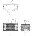
図10に示すように、検査装置60は、CCDカメラまたはCMOSセンサから構成されるセンサ部63を有する。センサ部63は、印刷媒体50の印刷面50aで反射された光を受光する。センサ部63は、受光した光を電気信号に変換する。検査装置60は、センサ部63に接続された不図示の処理装置を用いて、電気信号を解析し、処理することにより、印刷濃度、ドット抜け、印刷位置などを検査する。
As shown in FIG. 10, the
検査装置60は、検査した印刷濃度等に基づいて印刷状態を判断する。検査装置60は、印刷状態が不良であると判断すると、制御部40へエラー信号を送出する。制御部40は、エラー信号を受信すると、上述したメンテナンス動作を開始する。
The
上記の実施の形態では、キャッピング機構141を印刷ヘッド装置11に搭載したが、キャッピング機構141をプリンタのフレームに搭載するようにしてもよい。
In the above embodiment, the
上記の実施の形態では、垂直移動手段131により印刷ヘッド111を垂直方向に移動し、水平移動手段131により印刷ヘッド111を水平方向に移動したが、印刷ヘッド111がプラテンローラ22に接離する方向、すなわちキャッピング機構141に接離する第1の方向と当該第1の方向に直交しかつキャッピング機構141から離間してプラテンローラ22に対向する第2の方向とに移動する構成であればよく、例えば印刷ヘッド111を上下方向に斜めに移動してプラテンローラ22に接離させるとともに当該移動方向と直交する方向に印刷ヘッド111を移動するようにしてもよい。この場合、キャッピング機構141はプラテンローラ22の延伸方向と直交する方向へ印刷ヘッド111に並んで位置するように印刷ヘッド111の移動方向に応じて適宜配置される。
In the above-described embodiment, the
上記の実施の形態では、印刷ヘッド装置11の垂直移動手段131により、ヘッド部111aがキャッピング機構141のキャップ142に相対して移動されて、ノズル面111bにキャップ142が被着される。しかし、キャッピング機構141が垂直移動手段を有し、キャップ142を、ヘッド部111aのノズル面111bに相対してノズル面111bに接離する方向に移動するようにしてもよい。この場合、印刷位置からヘッドキャップ位置まで水平に移動する経路上に印刷ヘッド111の待避位置を設定すれば、印刷ヘッド装置11の垂直移動手段131を省略することができる。
In the above-described embodiment, the
上記の実施の形態では、プラテンとして、プラテンローラ22を用いたが、これに限らず、プリンタのフレームに固定される矩形平板状の平プラテンを用いるようにしてもよい。この場合には、キャッピング機構が印刷媒体の搬送路を境として印刷ヘッドの配置側に平プラテンの延伸方向に直交する方向に印刷ヘッドと並んで配置される。
In the above embodiment, the
上記の実施の形態では、印刷ヘッド装置11を所定の印刷位置で停止させるとともに、プラテンローラ22を連続的に回転させ、印刷媒体50を搬送しつつ印刷ヘッド111を駆動して印刷媒体50の印刷面50aに所望の文字等を印刷するプリンタに適用したが、これに限らず、印刷ヘッド装置11を印刷媒体50の搬送方向と直交する方向に移動しつつ印刷ヘッド111を駆動して印刷媒体50に印刷するシリアルプリンタであっても適用可能である。
In the above embodiment, the
上記の実施の形態では、印刷媒体50は、基材と定着層から構成される。しかし、印刷媒体50の構成は、これに限定されるものではない。例えば、基材がインクを定着可能な材料から構成される場合には、定着層を省略することができる。また、印刷媒体50は、基材と、定着層と、定着層の上に積層された樹脂層とから構成されてもよい。この場合、樹脂層は、インクが樹脂層を通過して定着層に保持されるように、熱可塑性の高分子微粒子または多孔質の高分子から構成される。樹脂層は、加熱されると溶融して樹脂膜を形成し、定着層に保持されたインクの色素をコーティングにより保護する。
In the above embodiment, the
印刷媒体50は、基材と、定着層と、定着層の上に積層された表面層とから構成されてもよい。この場合、表面層は、熱可塑性に限定されない多孔質の高分子から構成される。表面層は、印刷時には、インクを浸透させて定着層に保持させ、加熱されてインクが定着層に定着された後、定着層から剥離される。
The
1 プリンタ
10 印刷部
11 印刷ヘッド装置
16 ホルダ
17 ホルダガイド
20 搬送装置
21 送りローラ
22 プラテンローラ
26 モータ
30 加熱部
31 ケース
32 前面パネル
33 加熱器
34 ファン
40 制御部
50 印刷媒体
111 印刷ヘッド
111b ノズル面
141 キャッピング機構
142 キャップ
142a リップ
142b 突起
143 キャップホルダ
143a 案内溝
144 弾性部材
145 ストッパ
DESCRIPTION OF SYMBOLS 1
Claims (12)
前記プラテンに対向して配置され、複数のノズル孔が配置されたノズル面を有し、前記複数のノズル孔からインクを吐出して前記印刷媒体に印刷する印刷ヘッドと、
前記印刷ヘッドの前記ノズル面に密着して該ノズル面を覆うキャップを保持するキャッピング機構と、
前記印刷ヘッドを移動する移動手段と、
を備え、
前記キャップが、前記移動手段による前記印刷ヘッドの移動に伴って前記ノズル面に接離する方向に移動し、
前記キャッピング機構は、前記キャップが前記印刷ヘッドの前記ノズル面から離脱するとき、前記キャップの少なくとも一端の動きを規制して、前記キャップを前記ノズル面に対して傾斜させる規制手段を有する、
ことを特徴とするプリンタ。 A platen that supports the print medium;
A print head that is disposed to face the platen, has a nozzle surface on which a plurality of nozzle holes are disposed, and discharges ink from the plurality of nozzle holes to print on the print medium;
A capping mechanism that holds a cap that closely contacts the nozzle surface of the print head and covers the nozzle surface;
Moving means for moving the print head;
With
The cap moves in a direction of contacting and separating from the nozzle surface with the movement of the print head by the moving means;
The capping mechanism has a restricting means for restricting movement of at least one end of the cap and tilting the cap with respect to the nozzle surface when the cap is detached from the nozzle surface of the print head.
A printer characterized by that.
前記一方のストッパと前記他方のストッパとは、前記ノズル面からの距離が異なる位置で前記一端側の突起部と前記他端側の突起部に、それぞれ当接するように配置された、ことを特徴とする請求項1に記載のプリンタ。 The restricting means is in contact with a protrusion provided on the one end side of the cap, and is in contact with one stopper for restricting movement of the one end and a protrusion provided on the other end side of the cap. Having the other stopper for regulating the movement of the other end,
The one stopper and the other stopper are disposed so as to abut on the one end-side projection and the other end-side projection, respectively, at positions where the distance from the nozzle surface is different. The printer according to claim 1.
前記保持部材に、前記突起部を前記ノズル面に接離する方向に沿って案内する案内溝が形成された、ことを特徴とする請求項1又は2に記載のプリンタ。 The capping mechanism has a holding member for holding the cap;
3. The printer according to claim 1, wherein the holding member is formed with a guide groove that guides the protrusion along a direction in which the protrusion is in contact with or separated from the nozzle surface.
前記印刷ヘッドを収容する筐体と、
前記印刷ヘッドの前記ノズル面に密着して該ノズル面を覆うキャップを保持するキャッピング機構と、
前記印刷ヘッドを移動する移動手段と、
を備え、
前記キャップが、前記移動手段による前記印刷ヘッドの移動に伴って前記ノズル面に接離する方向に移動し、
前記キャッピング機構は、前記キャップが前記印刷ヘッドの前記ノズル面から離脱するとき、前記キャップの少なくとも一端の動きを規制して、前記キャップを前記ノズル面に対して傾斜させる規制手段を有する、
ことを特徴とする印刷ヘッド装置。 A print head disposed opposite to the platen and having a nozzle surface on which a plurality of nozzle holes are disposed;
A housing for accommodating the print head;
A capping mechanism that holds a cap that closely contacts the nozzle surface of the print head and covers the nozzle surface;
Moving means for moving the print head;
With
The cap moves in a direction of contacting and separating from the nozzle surface with the movement of the print head by the moving means;
The capping mechanism has a restricting means for restricting movement of at least one end of the cap and tilting the cap with respect to the nozzle surface when the cap is detached from the nozzle surface of the print head.
A print head device.
前記一方のストッパと前記他方のストッパとは、前記ノズル面からの距離が異なる位置で前記一端側の突起部と前記他端側の突起部に、それぞれ当接するように配置された、ことを特徴とする請求項6に記載の印刷ヘッド装置。 The restricting means is in contact with a protrusion provided on the one end side of the cap, and is in contact with one stopper for restricting movement of the one end and a protrusion provided on the other end side of the cap. Having the other stopper for regulating the movement of the other end,
The one stopper and the other stopper are disposed so as to abut on the one end-side projection and the other end-side projection, respectively, at positions where the distance from the nozzle surface is different. The print head device according to claim 6.
前記保持部材に、前記突起部を前記ノズル面に接離する方向に沿って案内する案内溝が形成された、ことを特徴とする請求項6又は7に記載の印刷ヘッド装置。 The capping mechanism has a holding member for holding the cap;
8. The print head device according to claim 6, wherein the holding member is formed with a guide groove that guides the protrusion along a direction in which the protrusion is in contact with or separated from the nozzle surface. 9.
Priority Applications (1)
| Application Number | Priority Date | Filing Date | Title |
|---|---|---|---|
| JP2006012288A JP2007190849A (en) | 2006-01-20 | 2006-01-20 | Printer and print head |
Applications Claiming Priority (1)
| Application Number | Priority Date | Filing Date | Title |
|---|---|---|---|
| JP2006012288A JP2007190849A (en) | 2006-01-20 | 2006-01-20 | Printer and print head |
Publications (1)
| Publication Number | Publication Date |
|---|---|
| JP2007190849A true JP2007190849A (en) | 2007-08-02 |
Family
ID=38446900
Family Applications (1)
| Application Number | Title | Priority Date | Filing Date |
|---|---|---|---|
| JP2006012288A Pending JP2007190849A (en) | 2006-01-20 | 2006-01-20 | Printer and print head |
Country Status (1)
| Country | Link |
|---|---|
| JP (1) | JP2007190849A (en) |
Cited By (3)
| Publication number | Priority date | Publication date | Assignee | Title |
|---|---|---|---|---|
| KR101074477B1 (en) | 2009-05-07 | 2011-10-17 | 주식회사 디지아이 | Nozzle dryness prevention device of head |
| JP2017042997A (en) * | 2015-08-26 | 2017-03-02 | 株式会社Okiデータ・インフォテック | inkjet printer |
| CN106827817A (en) * | 2015-12-23 | 2017-06-13 | 石立公 | For the stopper with inner bulge of random labelling head |
Citations (8)
| Publication number | Priority date | Publication date | Assignee | Title |
|---|---|---|---|---|
| JPH03290260A (en) * | 1989-12-26 | 1991-12-19 | Canon Inc | Ink jet device and recording system unit cartridge |
| JPH07246711A (en) * | 1994-03-11 | 1995-09-26 | Canon Aptecs Kk | Recovery device for ink jet head and printer equipped with said device |
| JPH09131882A (en) * | 1995-11-10 | 1997-05-20 | Ricoh Co Ltd | Ink jet recording device |
| JP2000006430A (en) * | 1998-06-24 | 2000-01-11 | Seiko Epson Corp | Ink jet recording device |
| JP2001253082A (en) * | 2000-03-13 | 2001-09-18 | Fuji Xerox Co Ltd | Apparatus for preventing dry up of ink, container for ink jet recording head, ink jet recorder, and method for preventing dry up of ink |
| JP2002355982A (en) * | 2001-05-31 | 2002-12-10 | Olympus Optical Co Ltd | Apparatus for recovering ink jet printer |
| JP2003200581A (en) * | 2002-01-08 | 2003-07-15 | Sharp Corp | Ink jet type image forming device |
| JP2004009576A (en) * | 2002-06-07 | 2004-01-15 | Canon Inc | Ink jet recording apparatus and cleaning mechanism of the recording apparatus |
-
2006
- 2006-01-20 JP JP2006012288A patent/JP2007190849A/en active Pending
Patent Citations (8)
| Publication number | Priority date | Publication date | Assignee | Title |
|---|---|---|---|---|
| JPH03290260A (en) * | 1989-12-26 | 1991-12-19 | Canon Inc | Ink jet device and recording system unit cartridge |
| JPH07246711A (en) * | 1994-03-11 | 1995-09-26 | Canon Aptecs Kk | Recovery device for ink jet head and printer equipped with said device |
| JPH09131882A (en) * | 1995-11-10 | 1997-05-20 | Ricoh Co Ltd | Ink jet recording device |
| JP2000006430A (en) * | 1998-06-24 | 2000-01-11 | Seiko Epson Corp | Ink jet recording device |
| JP2001253082A (en) * | 2000-03-13 | 2001-09-18 | Fuji Xerox Co Ltd | Apparatus for preventing dry up of ink, container for ink jet recording head, ink jet recorder, and method for preventing dry up of ink |
| JP2002355982A (en) * | 2001-05-31 | 2002-12-10 | Olympus Optical Co Ltd | Apparatus for recovering ink jet printer |
| JP2003200581A (en) * | 2002-01-08 | 2003-07-15 | Sharp Corp | Ink jet type image forming device |
| JP2004009576A (en) * | 2002-06-07 | 2004-01-15 | Canon Inc | Ink jet recording apparatus and cleaning mechanism of the recording apparatus |
Cited By (3)
| Publication number | Priority date | Publication date | Assignee | Title |
|---|---|---|---|---|
| KR101074477B1 (en) | 2009-05-07 | 2011-10-17 | 주식회사 디지아이 | Nozzle dryness prevention device of head |
| JP2017042997A (en) * | 2015-08-26 | 2017-03-02 | 株式会社Okiデータ・インフォテック | inkjet printer |
| CN106827817A (en) * | 2015-12-23 | 2017-06-13 | 石立公 | For the stopper with inner bulge of random labelling head |
Similar Documents
| Publication | Publication Date | Title |
|---|---|---|
| US7594722B2 (en) | Image forming apparatus and method | |
| US7467845B2 (en) | Image forming apparatus | |
| JP4640478B2 (en) | Image recording device | |
| US8282188B2 (en) | Inkjet head cleaning apparatus, image recording apparatus and inkjet head cleaning method | |
| JP5952669B2 (en) | Liquid ejection device and liquid ejection head moisturizing device | |
| JP6535621B2 (en) | Method and apparatus for cleaning a print head of an inkjet printer | |
| JP2001071521A (en) | Inkjet printer | |
| CN101376288B (en) | Inkjet recording equipment | |
| WO2003076192A1 (en) | Liquid ejecting head, method of cleaning the ejecting head, and liquid ejecting device | |
| JP6527073B2 (en) | System and method for image processing in an aqueous ink jet printer | |
| JP5798092B2 (en) | Liquid ejection device and liquid ejection head moisturizing device | |
| JP2009285870A (en) | Carriage unit and inkjet recorder | |
| JP2007062115A (en) | Liquid ejecting apparatus and recording apparatus | |
| JP2007190849A (en) | Printer and print head | |
| CN101357536B (en) | Ink jet recording apparatus | |
| JP4850021B2 (en) | Liquid ejection device | |
| JP4964812B2 (en) | Head cleaning mechanism and image recording apparatus | |
| JP2008254190A (en) | Liquid ejection device | |
| JP2008055733A (en) | Inkjet printer | |
| JP5808461B2 (en) | Inkjet recording device | |
| JP2007062152A (en) | Printer and printing head device | |
| JP5936512B2 (en) | Liquid discharge head and image recording apparatus | |
| JP5872886B2 (en) | Inkjet recording device | |
| JP2004025666A (en) | Sheet conveyance method | |
| JP2007090612A (en) | Printer and print head unit |
Legal Events
| Date | Code | Title | Description |
|---|---|---|---|
| A621 | Written request for application examination |
Free format text: JAPANESE INTERMEDIATE CODE: A621 Effective date: 20070820 |
|
| A977 | Report on retrieval |
Free format text: JAPANESE INTERMEDIATE CODE: A971007 Effective date: 20100405 |
|
| A131 | Notification of reasons for refusal |
Free format text: JAPANESE INTERMEDIATE CODE: A131 Effective date: 20100413 |
|
| A02 | Decision of refusal |
Free format text: JAPANESE INTERMEDIATE CODE: A02 Effective date: 20100803 |