JP2007190860A - Liquid ejection head and image forming apparatus - Google Patents
Liquid ejection head and image forming apparatus Download PDFInfo
- Publication number
- JP2007190860A JP2007190860A JP2006012750A JP2006012750A JP2007190860A JP 2007190860 A JP2007190860 A JP 2007190860A JP 2006012750 A JP2006012750 A JP 2006012750A JP 2006012750 A JP2006012750 A JP 2006012750A JP 2007190860 A JP2007190860 A JP 2007190860A
- Authority
- JP
- Japan
- Prior art keywords
- liquid
- flow path
- nozzle
- ink
- channel
- Prior art date
- Legal status (The legal status is an assumption and is not a legal conclusion. Google has not performed a legal analysis and makes no representation as to the accuracy of the status listed.)
- Pending
Links
Images


Classifications
-
- B—PERFORMING OPERATIONS; TRANSPORTING
- B41—PRINTING; LINING MACHINES; TYPEWRITERS; STAMPS
- B41J—TYPEWRITERS; SELECTIVE PRINTING MECHANISMS, i.e. MECHANISMS PRINTING OTHERWISE THAN FROM A FORME; CORRECTION OF TYPOGRAPHICAL ERRORS
- B41J2/00—Typewriters or selective printing mechanisms characterised by the printing or marking process for which they are designed
- B41J2/005—Typewriters or selective printing mechanisms characterised by the printing or marking process for which they are designed characterised by bringing liquid or particles selectively into contact with a printing material
- B41J2/01—Ink jet
- B41J2/135—Nozzles
- B41J2/14—Structure thereof only for on-demand ink jet heads
- B41J2/14008—Structure of acoustic ink jet print heads
Landscapes
- Particle Formation And Scattering Control In Inkjet Printers (AREA)
Abstract
Description
本発明は、液体吐出ヘッド及び画像形成装置に係り、特に、少なくとも1つの壁面が弾性部材で構成される液体流路(ノズル流路)を有する液体吐出ヘッドに関する。 The present invention relates to a liquid discharge head and an image forming apparatus, and more particularly to a liquid discharge head having a liquid flow path (nozzle flow path) having at least one wall surface made of an elastic member.
多数のノズルを有するヘッド(液体吐出ヘッド)を搭載し、各ノズルからインク滴を吐出することにより、記録媒体上に所望の画像を記録するインクジェット記録装置が従来より知られている。この種のヘッドには、例えば、圧電素子(ピエゾ素子)に代表されるアクチュエータの変形を利用して、圧力室内のインクを加圧し、圧力室に連通するノズルからインク滴を吐出する圧電方式のものがある。 2. Description of the Related Art An ink jet recording apparatus that records a desired image on a recording medium by mounting a head having a large number of nozzles (liquid ejection head) and ejecting ink droplets from each nozzle is conventionally known. For this type of head, for example, a piezoelectric type that pressurizes ink in a pressure chamber by using deformation of an actuator represented by a piezoelectric element (piezo element) and ejects ink droplets from a nozzle communicating with the pressure chamber. There is something.
近年、高解像、高精細な画像を高速記録できるようにすることが望まれており、様々な機能を付加した高粘度インクや微液滴のインク吐出を実現可能なヘッドの開発が必要となっている。しかし、従来の圧電方式のヘッドにおいて高粘度(例えば、5〜10cp程度)且つ微液滴(例えば、0.5pl程度)のインク吐出を実現しようとすると、次のような様々な問題がある。 In recent years, it has been desired to enable high-resolution and high-definition images to be recorded at high speed, and it is necessary to develop a head capable of ejecting high-viscosity ink and various droplets with various functions. It has become. However, when it is attempted to eject ink with high viscosity (for example, about 5 to 10 cp) and fine droplets (for example, about 0.5 pl) in a conventional piezoelectric head, there are the following various problems.
まず、従来の圧電方式のヘッドでは、ノズルから吐出されたインク滴が柱状となって尾を引く形で飛翔する現象(尾引き現象)が生じやすく、これにより、主たるインク滴に付随して微小なインク滴(以下、サテライト滴という。)が発生し、このサテライト滴が記録媒体に付着して、画像品質の劣化を招く場合がある。このようなサテライト滴の発生を抑えるため、例えば、特許文献1では、アクチュエータの駆動電圧の変化速度を2段階に切り替えてインク滴を吐出している。しかしながら、インク粘度が高くなるとインク柱が長くなり、内部の速度分布も散漫となってくるため、多数のサテライト滴が発生する可能性がある。また、ノズルから吐出されるインク滴が微液滴化されると、インク柱自体が細くなるためRayleigh-Taylor不安定性によりサテライト滴が発生しやすくなる。このため、高粘度且つ微液滴を吐出する場合には、特許文献1の如く、アクチュエータの駆動電圧を工夫しても、このような現象を軽減することは困難である。 First, in a conventional piezoelectric head, the ink droplets ejected from the nozzles tend to fly in a columnar shape and fly in a tail-like manner (tailing phenomenon). Ink droplets (hereinafter referred to as satellite droplets) may be generated, and the satellite droplets may adhere to the recording medium, resulting in degradation of image quality. In order to suppress the occurrence of such satellite droplets, for example, in Patent Document 1, ink droplets are ejected by switching the change speed of the driving voltage of the actuator in two stages. However, as the ink viscosity increases, the ink column becomes longer and the internal velocity distribution becomes diffuse, and thus a large number of satellite droplets may be generated. In addition, when the ink droplets ejected from the nozzle are made into fine droplets, the ink column itself becomes thin, so that satellite droplets are likely to be generated due to Rayleigh-Taylor instability. For this reason, when ejecting high-viscosity and fine droplets, it is difficult to reduce such a phenomenon even if the drive voltage of the actuator is devised as in Patent Document 1.
また、高粘度インクを吐出可能にするためには、例えば、圧電体の積層数を増やしたり、駆動電圧を上げたりしてアクチュエータをパワーアップさせることが必要となるが、いずれの場合においても限界がある。更に、リフィル遅れによる吐出周波数の低下という問題もある。 In order to make it possible to discharge high-viscosity ink, for example, it is necessary to increase the number of stacked piezoelectric bodies or increase the drive voltage to increase the actuator power. There is. Further, there is a problem that the discharge frequency is lowered due to refill delay.
また、微液滴を吐出可能にするためには、アクチュエータの駆動周波数を上げなければならない。従来の圧電方式のヘッドでは、アクチュエータの駆動周波数をヘッド(圧力室)内流体の共振周波数に略一致させて吐出を行う、いわゆる全系共振を使った吐出を行っている。従って、アクチュエータの駆動周波数を上げるためには圧力室のサイズ(容積)を小さくして圧力室の共振周波数を下げなければならず、ヘッド設計上の大きな制約となってしまう。
このように従来の圧電方式のヘッドにおいて高粘度且つ微液滴のインク吐出を実現させさせるためには様々な問題があり、その実現は非常に困難である。 As described above, there are various problems in realizing the ejection of ink with high viscosity and fine droplets in the conventional piezoelectric head, and it is very difficult to realize it.
本発明はこのような事情に鑑みてなされたもので、高粘度且つ微液滴の液体吐出を可能にし、好ましい画像品質を実現することのできる液体吐出ヘッド及び画像形成装置を提供することを目的とする。 The present invention has been made in view of such circumstances, and an object of the present invention is to provide a liquid discharge head and an image forming apparatus that can discharge liquid with high viscosity and fine droplets and can realize preferable image quality. And
前記目的を達成するために、請求項1に記載の発明は、少なくとも1つの壁面が弾性部材で構成される液体流路と、前記液体流路の一端に設けられるノズルと、前記液体流路内の液体に圧力脈動波を発生させる圧力発生手段と、を備え、前記圧力脈動波をソリトン波として前記液体流路内を伝播可能となるように前記液体流路及び前記圧力発生手段が構成されていることを特徴とする液体吐出ヘッドを提供する。 In order to achieve the above object, the invention according to claim 1 is directed to a liquid channel having at least one wall surface made of an elastic member, a nozzle provided at one end of the liquid channel, and the liquid channel. Pressure generating means for generating a pressure pulsating wave in the liquid, and the liquid flow path and the pressure generating means are configured so that the pressure pulsating wave can be propagated through the liquid flow path as a soliton wave. A liquid discharge head is provided.
本発明によれば、液体流路内の圧力脈動波をソリトン波として高効率で伝播させることができ、また、液体流路の一端に位置するノズル部分におけるソリトン破壊によって液柱の過度の発達を抑制した状態で粒子化することができる。これにより、高粘度且つ微液滴をノズルから吐出することが可能となり、好ましい画像品質を実現することができる。 According to the present invention, the pressure pulsation wave in the liquid channel can be propagated with high efficiency as a soliton wave, and excessive development of the liquid column is caused by soliton breakdown in the nozzle portion located at one end of the liquid channel. Particles can be formed in a suppressed state. Thereby, it becomes possible to discharge a highly viscous and fine droplet from a nozzle, and can implement | achieve preferable image quality.
請求項2に記載の発明は、請求項1に記載の液体吐出ヘッドであって、前記液体流路は略円筒状に構成され、前記液体流路及び前記圧力発生手段は、前記液体流路を伝播する圧力脈動波の半値幅をw、前記圧力脈動波の速度をv、前記液体流路の半径をa、前記液体流路の隔壁の厚さをh、前記圧力脈動波の最大振幅をr0、前記液体流路の隔壁の密度をρR、前記液体流路内の液体の密度をρ0、前記液体流路の隔壁のヤング率をEとするとき、次式 A second aspect of the present invention is the liquid ejection head according to the first aspect, wherein the liquid flow path is formed in a substantially cylindrical shape, and the liquid flow path and the pressure generating means The half width of the propagating pressure pulsating wave is w, the velocity of the pressure pulsating wave is v, the radius of the liquid channel is a, the thickness of the partition wall of the liquid channel is h, and the maximum amplitude of the pressure pulsating wave is r. 0 , where ρ R is the density of the partition walls of the liquid channel, ρ 0 is the density of the liquid in the liquid channel, and E is the Young's modulus of the partition walls of the liquid channel,

請求項3に記載の発明は、請求項1に記載の液体吐出ヘッドであって、前記液体流路に相当する溝部を有する液体流路形成部材の前記溝部の開口面に弾性部材を設けたことを特徴とする。 The invention according to claim 3 is the liquid discharge head according to claim 1, wherein an elastic member is provided on an opening surface of the groove portion of the liquid flow path forming member having a groove portion corresponding to the liquid flow path. It is characterized by.
請求項3の態様によれば、構造が簡略化され製造適性に優れる。 According to the aspect of claim 3, the structure is simplified and the manufacturing aptitude is excellent.
また前記目的を達成するために、請求項4に記載の発明は、請求項1乃至請求項3のいずれか1項に記載の液体吐出ヘッドを備えたことを特徴とする画像形成装置を提供する。 In order to achieve the object, an invention according to claim 4 provides an image forming apparatus comprising the liquid discharge head according to any one of claims 1 to 3. .
本発明によれば、液体流路内の圧力脈動波をソリトン波として高効率で伝播させることができ、また、液体流路の一端に位置するノズル部分におけるソリトン破壊によって液柱の過度の発達を抑制した状態で粒子化することができる。これにより、高粘度且つ微液滴をノズルから吐出することが可能となり、好ましい画像品質を実現することができる。 According to the present invention, the pressure pulsation wave in the liquid channel can be propagated with high efficiency as a soliton wave, and excessive development of the liquid column is caused by soliton breakdown in the nozzle portion located at one end of the liquid channel. Particles can be formed in a suppressed state. Thereby, it becomes possible to discharge a highly viscous and fine droplet from a nozzle, and can implement | achieve preferable image quality.
以下、添付図面に従って本発明の好ましい実施形態(第1、第2の実施形態)について詳説する。 Hereinafter, preferred embodiments (first and second embodiments) of the present invention will be described in detail with reference to the accompanying drawings.
(第1の実施形態)
図1は、本発明に係る画像形成装置の一実施形態であるインクジェット記録装置の概略を示す全体構成図である。図1に示すように、このインクジェット記録装置10は、インクの色毎に設けられた複数のヘッド12K、12C、12M、12Yを有する印字部12と、各ヘッド12K、12C、12M、12Yに供給するインクを貯蔵しておくインク貯蔵/装填部14と、記録紙16を供給する給紙部18と、記録紙16のカールを除去するデカール処理部20と、前記印字部12のノズル面(インク吐出面)に対向して配置され、記録紙16の平面性を保持しながら記録紙16を搬送する吸着ベルト搬送部22と、印字部12による印字結果を読み取る印字検出部24と、印画済みの記録紙(プリント物)を外部に排紙する排紙部26と、を備えている。
(First embodiment)
FIG. 1 is an overall configuration diagram showing an outline of an ink jet recording apparatus which is an embodiment of an image forming apparatus according to the present invention. As shown in FIG. 1, the
図1では、給紙部18の一例としてロール紙(連続用紙)のマガジンが示されているが、紙幅や紙質等が異なる複数のマガジンを併設してもよい。また、ロール紙のマガジンに代えて、又はこれと併用して、カット紙が積層装填されたカセットによって用紙を供給してもよい。
In FIG. 1, a magazine for rolled paper (continuous paper) is shown as an example of the
ロール紙を使用する装置構成の場合、図1のように、裁断用のカッター28が設けられており、該カッター28によってロール紙は所望のサイズにカットされる。カッター28は、記録紙16の搬送路幅以上の長さを有する固定刃28Aと、該固定刃28Aに沿って移動する丸刃28Bとから構成されており、印字裏面側に固定刃28Aが設けられ、搬送路を挟んで印字面側に丸刃28Bが配置されている。なお、カット紙を使用する場合には、カッター28は不要である。
In the case of an apparatus configuration using roll paper, a
複数種類の記録紙を利用可能な構成にした場合、紙の種類情報を記録したバーコードあるいは無線タグ等の情報記録体をマガジンに取り付け、その情報記録体の情報を所定の読取装置によって読み取ることで、使用される用紙の種類を自動的に判別し、用紙の種類に応じて適切なインク吐出を実現するようにインク吐出制御を行うことが好ましい。 When multiple types of recording paper are used, an information recording body such as a barcode or wireless tag that records paper type information is attached to the magazine, and the information on the information recording body is read by a predetermined reader. Therefore, it is preferable to automatically determine the type of paper to be used and perform ink ejection control so as to realize appropriate ink ejection according to the type of paper.
給紙部18から送り出される記録紙16はマガジンに装填されていたことによる巻き癖が残り、カールする。このカールを除去するために、デカール処理部20においてマガジンの巻き癖方向と逆方向に加熱ドラム30で記録紙16に熱を与える。このとき、多少印字面が外側に弱いカールとなるように加熱温度を制御するとより好ましい。
The recording paper 16 delivered from the
デカール処理後、カットされた記録紙16は、吸着ベルト搬送部22へと送られる。吸着ベルト搬送部22は、ローラー31、32間に無端状のベルト33が巻き掛けられた構造を有し、少なくとも印字部12のノズル面及び印字検出部24のセンサ面に対向する部分が平面をなすように構成されている。
After the decurling process, the cut recording paper 16 is sent to the suction
ベルト33は、記録紙16の幅よりも広い幅寸法を有しており、ベルト面には多数の吸引孔(不図示)が形成されている。図1に示したとおり、ローラー31、32間に掛け渡されたベルト33の内側において印字部12のノズル面及び印字検出部24のセンサ面に対向する位置には吸着チャンバー34が設けられており、この吸着チャンバー34をファン35で吸引して負圧にすることによってベルト33上の記録紙16が吸着保持される。
The
ベルト33が巻かれているローラー31、32の少なくとも一方にモータ(不図示)の動力が伝達されることにより、ベルト33は図1において、時計回り方向に駆動され、ベルト33上に保持された記録紙16は、図1の左から右へと搬送される。
The power of a motor (not shown) is transmitted to at least one of the
縁無しプリント等を印字するとベルト33上にもインクが付着するので、ベルト33の外側の所定位置(印字領域以外の適当な位置)にベルト清掃部36が設けられている。ベルト清掃部36の構成について詳細は図示しないが、例えば、ブラシ・ロール、吸水ロール等をニップする方式、清浄エアーを吹き掛けるエアーブロー方式、あるいはこれらの組み合わせなどがある。清掃用ロールをニップする方式の場合、ベルト線速度とローラー線速度を変えると清掃効果が大きい。
Since ink adheres to the
なお、吸着ベルト搬送部22に代えて、ローラー・ニップ搬送機構を用いる態様も考えられるが、印字領域をローラー・ニップ搬送すると、印字直後に用紙の印字面にローラーが接触するので、画像が滲み易いという問題がある。従って、本例のように、印字領域では画像面と接触させない吸着ベルト搬送が好ましい。
Although a mode using a roller / nip transport mechanism instead of the suction
吸着ベルト搬送部22により形成される用紙搬送路上において印字部12の上流側には、加熱ファン40が設けられている。加熱ファン40は、印字前の記録紙16に加熱空気を吹きつけ、記録紙16を加熱する。印字直前に記録紙16を加熱しておくことにより、インクが着弾後乾き易くなる。
A
印字部12は、最大紙幅に対応する長さを有するライン型ヘッドを紙搬送方向(副走査方向)と直交する方向(主走査方向)に配置した、いわゆるフルライン型のヘッドとなっている。印字部12を構成する各ヘッド12K、12C、12M、12Yは、本インクジェット記録装置10が対象とする最大サイズの記録紙16の少なくとも一辺を超える長さにわたってインク吐出口(ノズル)が配列されたライン型ヘッドで構成されている。
The
記録紙16の搬送方向(紙搬送方向)に沿って上流側(図1の左側)から黒(K)、シアン(C)、マゼンタ(M)、イエロー(Y)の順に各色インクに対応したヘッド12K、12C、12M、12Yが配置されている。記録紙16を搬送しつつ各ヘッド12K、12C、12M、12Yからそれぞれ色インクを吐出することにより記録紙16上にカラー画像を形成し得る。
A head corresponding to each color ink in the order of black (K), cyan (C), magenta (M), and yellow (Y) from the upstream side (left side in FIG. 1) along the conveyance direction (paper conveyance direction) of the recording paper 16. 12K, 12C, 12M, and 12Y are arranged. A color image can be formed on the recording paper 16 by discharging the color inks from the
このように、紙幅の全域をカバーするフルラインヘッドがインク色毎に設けられてなる印字部12によれば、紙搬送方向(副走査方向)について記録紙16と印字部12を相対的に移動させる動作を一回行うだけで(すなわち、一回の副走査で)記録紙16の全面に画像を記録することができる。これにより、ヘッドが紙搬送方向と直交する方向(主走査方向)に往復動作するシャトル型ヘッドに比べて高速印字が可能であり、生産性を向上させることができる。
Thus, according to the
なお本例では、KCMYの標準色(4色)の構成を例示したが、インク色や色数の組み合わせについては本実施形態には限定されず、必要に応じて淡インク、濃インクを追加してもよい。例えば、ライトシアン、ライトマゼンタ等のライト系インクを吐出するヘッドを追加する構成も可能である。 In this example, the configuration of KCMY standard colors (four colors) is illustrated, but the combination of ink colors and the number of colors is not limited to this embodiment, and light ink and dark ink are added as necessary. May be. For example, it is possible to add a head for ejecting light-colored ink such as light cyan and light magenta.
図1に示したように、インク貯蔵/装填部14は、各ヘッド12K、12C、12M、12Yに対応する色のインクを貯蔵するタンクを有し、各タンクは図示を省略した管路を介して各ヘッド12K、12C、12M、12Yと連通されている。また、インク貯蔵/装填部14は、インク残量が少なくなるとその旨を報知する報知手段(表示手段、警告音発生手段等)を備えるとともに、色間の誤装填を防止するための機構を有している。
As shown in FIG. 1, the ink storage /
印字検出部24は、印字部12の打滴結果を撮像するためのイメージセンサ(ラインセンサ等)を含み、該イメージセンサによって読み取った打滴画像からノズルの目詰まりその他の吐出不良をチェックする手段として機能する。
The
本例の印字検出部24は、少なくとも各ヘッド12K、12C、12M、12Yによるインク吐出幅(画像記録幅)よりも幅の広い受光素子列を有するラインセンサで構成される。このラインセンサは、赤(R)の色フィルタが設けられた光電変換素子(画素)がライン状に配列されたRセンサ列と、緑(G)の色フィルタが設けられたGセンサ列と、青(B)の色フィルタが設けられたBセンサ列とからなる色分解ラインCCDセンサで構成されている。なお、ラインセンサに代えて、受光素子が二次元配列されて成るエリアセンサを用いることも可能である。
The
印字検出部24は、各色のヘッド12K、12C、12M、12Yにより印字されたテストパターンを読み取り、各ヘッドの吐出検出を行う。吐出判定は、吐出の有無、ドットサイズの測定、ドット着弾位置の測定等で構成される。
The
印字検出部24の後段には、後乾燥部42が設けられている。後乾燥部42は、印字された画像面を乾燥させる手段であり、例えば、加熱ファンが用いられる。印字後のインクが乾燥するまでは印字面と接触することは避けたほうが好ましいので、熱風を吹きつける方式が好ましい。
A
多孔質のペーパに染料系インクで印字した場合などでは、加圧によりペーパの孔を塞ぐことでオゾンなど、染料分子を壊す原因となるものと接触することを防ぐことで画像の耐候性がアップする効果がある。 When printing on porous paper with dye-based ink, the weather resistance of the image is improved by preventing contact with ozone or other things that cause dye molecules to break by blocking the paper holes by pressurization. There is an effect to.
後乾燥部42の後段には、加熱・加圧部44が設けられている。加熱・加圧部44は、画像表面の光沢度を制御するための手段であり、画像面を加熱しながら所定の表面凹凸形状を有する加圧ローラー45で加圧し、画像面に凹凸形状を転写する。
A heating /
このようにして生成されたプリント物は、排紙部26から排出される。本来プリントすべき本画像(目的の画像を印刷したもの)とテスト印字とは分けて排出することが好ましい。このインクジェット記録装置10では、本画像のプリント物と、テスト印字のプリント物とを選別してそれぞれの排出部26A、26Bへと送るために排紙経路を切り換える選別手段(不図示)が設けられている。なお、大きめの用紙に本画像とテスト印字とを同時に並列に形成する場合は、カッター(第2のカッター)48によってテスト印字の部分を切り離す。カッター48は、排紙部26の直前に設けられており、画像余白部にテスト印字を行った場合に、本画像とテスト印字部を切断するためのものである。カッター48の構造は前述した第1のカッター28と同様であり、固定刃48Aと丸刃48Bとから構成されている。
The printed matter generated in this manner is outputted from the
また、図示を省略したが、本画像の排出部26Aには、オーダー別に画像を集積するソーターが設けられている。
Although not shown, the
次に、ヘッド12K、12C、12M、12Yの構成について説明する。尚、各ヘッド12K、12C、12M、12Yの構成は共通しているので、以下では、これらを代表して符号50によってヘッドを示すものとする。
Next, the configuration of the
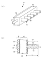
図2はヘッド50の構成を示す説明図であり、(a)は外観斜視図、(b)は一部断面図である。図2に示すヘッド50には、その長手方向に沿って円柱状のノズル流路形成部材52が複数設けられている。尚、図2(a)では便宜的に5つのノズル流路形成部材52を表示しているが、実際には非常に多くのノズル流路形成部材52が設けられる。各ノズル流路形成部材52は共通流路形成部材54の一端面に固着されており、その反対側の端面(共通流路形成部材54のノズル流路形成部材52側とは反対側の端面)には圧電アクチュエータ56(圧力発生手段)が配置されている。
2A and 2B are explanatory views showing the configuration of the
図2(b)に示すように、各ノズル流路形成部材52の内部にはその軸方向に沿って延びる円筒状のノズル流路58(液体流路)が形成されている。ノズル流路58の一端に形成される開口はインク滴を吐出するためのノズル51である。ノズル流路58の他端は共通流路60に連通している。共通流路60は、共通流路形成部材54に形成される凹部を圧電アクチュエータ56で塞いで形成される空間に相当する。共通流路60には、図1に示したインク貯蔵/装填部14から管路62を介して供給されるインクが貯留される。
As shown in FIG. 2B, a cylindrical nozzle channel 58 (liquid channel) extending along the axial direction is formed inside each nozzle
圧電アクチュエータ56は、平板状の圧電体64とその両面に配置される個別電極66、共通電極68から構成される。個別電極66はノズル51(ノズル流路58)毎に設けられ、圧電体64の共通流路60側とは反対側の面上で各ノズル流路58にそれぞれ対向する位置に配置される。共通電極68は圧電体64の共通流路60側の面全体にわたって形成されている。共通電極68の表面には樹脂等の絶縁保護膜(不図示)が形成されており、共通流路60内に貯留されるインクに対する共通電極68の接液が防止されている。
The
個別電極66と共通電極68により挟まれた圧電体領域は電極66、68間に電圧を印加すると所定の変位を発生する変位発生部70となっている。本実施形態では、共通電極68は図示しない部分において接地された状態となっており、個別電極66に対して不図示の駆動回路から所定の駆動電圧が印加されるように構成されている。個別電極66に駆動電圧が印加されると、変位発生部70は共通流路60を挟んで対向する位置にあるノズル流路58に向かって撓むように変位する。これにより、共通流路60内のインクを介して圧力脈動波がノズル流路58内に入射し、その圧力脈動波はノズル流路58内のインク中を伝播し、ノズル流路58の一端に位置するノズル51からインク滴が吐出される。
The piezoelectric region sandwiched between the
本発明では、圧力脈動波がソリトン波としてノズル流路58内を伝播するようにノズル流路58及び圧電アクチュエータ56を構成したことを特徴としている。これにより、尾引き現象を低減することができるのでサテライト滴の発生が抑制され、高粘度且つ微液滴を吐出することが可能となる。
The present invention is characterized in that the
以下では、ノズル流路58及び圧電アクチュエータ56の具体的な構成条件について説明する。図3はノズル流路形成部材52の一部断面図である。まず、ノズル流路58内を伝播する圧力脈動波の半値幅をw、速度をvとし、ノズル流路58の半径をa、ノズル流路隔壁59の厚さをh、ノズル流路隔壁59の密度をρR、圧力脈動波の最大振幅をr0、ノズル流路58内の流体(インク)の密度をρ0、ノズル流路隔壁59のヤング率をEとするとき、次式の関係が成立することは一般的に知られている。
Hereinafter, specific configuration conditions of the
但し、〜付き変数は既知数、他は未知数とする。今、吐出体積を
However, ~ with variable known number, the other is an unknown. Now the discharge volume
また、吐出周波数をfとすると、ソリトン発生のトリガーとなる圧力脈動波のパルスを打ち出す周期はT=1/fである。この時間内に圧力脈動波(ソリトン波)がノズル流路58の終端であるノズル51に達した場合、そこでの反射ソリトン波が次に打ち出されるソリトン波と流路内で衝突する可能性がある。ソリトン波同士の衝突における相互作用は小さいが、伝播速度の低下を可能な限り抑制するためには、このようなノズル流路58内の多ソリトン化を避ける方向で設計することが好ましい。即ち、ノズル流路58の流路長をLとしたとき(図2(b)参照)、次式
Further, if the discharge frequency is f, the period for emitting a pulse of a pressure pulsation wave that triggers soliton generation is T = 1 / f. If the pressure pulsation wave (soliton wave) reaches the
第1の実施形態によれば、前記式(1)〜(4)を満たすようにノズル流路58及び圧電アクチュエータ56を構成することによって、ノズル流路58内の圧力脈動波をソリトン波として効率的に伝播することができる。また、ソリトンを用いることによって運動量をもつ流体領域が局在化するため、粒子化時の微液滴化が可能となり、インク柱の過度の発達による尾引き現象を低減することができる。これにより、サテライト滴の発生を抑制しつつ、高粘度且つ微液滴をノズルから吐出することが可能となり、好ましい画像品質を実現することができるようになる。
According to the first embodiment, the
また、本実施形態に係るヘッド50では、圧電アクチュエータ56の駆動周波数をヘッド50内流体(インク)の共振周波数に略一致させる必要がなく、圧電アクチュエータ56自身の共振周波数での駆動が可能となり、従来の圧電方式のヘッドに比べて高周波吐出が可能となる。特に、超音波領域の周波数を使うことでストリーミング効果(放射圧によって流体を押し出す効果)や、更に、ソリトン効果によって効率の良い伝播が行えることから、高粘度インクを用いる場合のリフィル性能を改善することができる。
Further, in the
尚、第1の実施形態ではヘッド50の長手方向に沿ってノズル流路58を1列に配列した態様を一例として示したが、ノズル流路58を複数列に配列する態様もある。
In the first embodiment, the mode in which the
(第2の実施形態)
次に、本発明に係る第2の実施形態について説明する。以下、既述した第1の実施形態と共通する部分については説明を省略し、本実施形態の特徴的な部分を中心に説明する。
(Second Embodiment)
Next, a second embodiment according to the present invention will be described. Hereinafter, description of parts common to the above-described first embodiment will be omitted, and description will be made focusing on characteristic parts of the present embodiment.
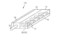
図4は第2の実施形態に係るヘッド150の外観斜視図である。図4中、図2と共通する部材については同一の番号を付している。このヘッド150の一部を構成するノズル流路形成部材74にはノズル流路58に相当する溝部72が複数設けられており、SUS等の平板状の弾性部材76が各溝部72の開口面に接合された構成となっている。このようにして構成されるノズル流路58はその軸方向に垂直な断面が矩形状となっている。
FIG. 4 is an external perspective view of the
第2の実施形態によれば、第1の実施形態に比べてノズル流路58内の圧力脈動波の伝播特性は若干劣るものの、尾引き現象を低減した状態で高粘度且つ微液滴をノズル51から吐出することができる。特に、第2の実施形態ではノズル流路58の一壁面が弾性部材76で構成される態様としたことにより、構造が簡略化され、製造適性により優れた構成となっている。
According to the second embodiment, although the propagation characteristics of the pressure pulsation wave in the
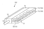
尚、本実施形態ではノズル流路58の一壁面が弾性部材76で構成される態様を一例として示したが、本発明の実施に際してはこれに限定されない。例えば、第2の実施形態の変形例として図5に示したヘッド150′のように、ノズル流路58の対向する両壁面を弾性部材76(76A、76B)で構成してもよい。また図示は省略するが、隣接するノズル流路58、58間の隔壁を弾性部材で構成するようにしてもよい。
In the present embodiment, an example in which one wall surface of the
以上、本発明の液体吐出ヘッド及び画像形成装置について詳細に説明したが、本発明は、以上の例には限定されず、本発明の要旨を逸脱しない範囲において、各種の改良や変形を行ってもよいのはもちろんである。 The liquid ejection head and the image forming apparatus of the present invention have been described in detail above. However, the present invention is not limited to the above examples, and various improvements and modifications are made without departing from the gist of the present invention. Of course it is also good.
10…インクジェット記録装置、50…ヘッド、51…ノズル、52…ノズル流路形成部材、56…圧電アクチュエータ、60…共通流路、74…ノズル流路形成部材、76…弾性部材、150、150′…ヘッド
DESCRIPTION OF
Claims (4)
前記液体流路の一端に設けられるノズルと、
前記液体流路内の液体に圧力脈動波を発生させる圧力発生手段と、を備え、
前記圧力脈動波をソリトン波として前記液体流路内を伝播可能となるように前記液体流路及び前記圧力発生手段が構成されていることを特徴とする液体吐出ヘッド。 A liquid flow path having at least one wall surface made of an elastic member;
A nozzle provided at one end of the liquid channel;
Pressure generating means for generating a pressure pulsation wave in the liquid in the liquid flow path,
The liquid discharge head, wherein the liquid flow path and the pressure generating means are configured so that the pressure pulsation wave can be propagated through the liquid flow path as a soliton wave.
前記液体流路及び前記圧力発生手段は、前記液体流路を伝播する圧力脈動波の半値幅をw、前記圧力脈動波の速度をv、前記液体流路の半径をa、前記液体流路の隔壁の厚さをh、前記圧力脈動波の最大振幅をr0、前記液体流路の隔壁の密度をρR、前記液体流路内の液体の密度をρ0、前記液体流路の隔壁のヤング率をEとするとき、次式
The liquid flow path and the pressure generating means have a half width of a pressure pulsation wave propagating through the liquid flow path, w a velocity of the pressure pulsation wave, v a radius of the liquid flow path, The thickness of the partition wall is h, the maximum amplitude of the pressure pulsation wave is r 0 , the density of the partition wall of the liquid channel is ρ R , the density of the liquid in the liquid channel is ρ 0 , and the partition wall of the liquid channel is When Young's modulus is E, the following formula
Priority Applications (2)
| Application Number | Priority Date | Filing Date | Title |
|---|---|---|---|
| JP2006012750A JP2007190860A (en) | 2006-01-20 | 2006-01-20 | Liquid ejection head and image forming apparatus |
| US11/654,631 US7661781B2 (en) | 2006-01-20 | 2007-01-18 | Liquid ejection head and image forming apparatus |
Applications Claiming Priority (1)
| Application Number | Priority Date | Filing Date | Title |
|---|---|---|---|
| JP2006012750A JP2007190860A (en) | 2006-01-20 | 2006-01-20 | Liquid ejection head and image forming apparatus |
Publications (1)
| Publication Number | Publication Date |
|---|---|
| JP2007190860A true JP2007190860A (en) | 2007-08-02 |
Family
ID=38285085
Family Applications (1)
| Application Number | Title | Priority Date | Filing Date |
|---|---|---|---|
| JP2006012750A Pending JP2007190860A (en) | 2006-01-20 | 2006-01-20 | Liquid ejection head and image forming apparatus |
Country Status (2)
| Country | Link |
|---|---|
| US (1) | US7661781B2 (en) |
| JP (1) | JP2007190860A (en) |
Cited By (1)
| Publication number | Priority date | Publication date | Assignee | Title |
|---|---|---|---|---|
| JP2024509866A (en) * | 2021-03-08 | 2024-03-05 | 株式会社リコー | Manifold length at printhead |
Family Cites Families (2)
| Publication number | Priority date | Publication date | Assignee | Title |
|---|---|---|---|---|
| JP3495761B2 (en) | 1992-07-21 | 2004-02-09 | セイコーエプソン株式会社 | Method of forming ink droplets in ink jet printer and ink jet recording apparatus |
| JPH1178030A (en) * | 1997-09-10 | 1999-03-23 | Brother Ind Ltd | Method of manufacturing inkjet head |
-
2006
- 2006-01-20 JP JP2006012750A patent/JP2007190860A/en active Pending
-
2007
- 2007-01-18 US US11/654,631 patent/US7661781B2/en not_active Expired - Fee Related
Cited By (1)
| Publication number | Priority date | Publication date | Assignee | Title |
|---|---|---|---|---|
| JP2024509866A (en) * | 2021-03-08 | 2024-03-05 | 株式会社リコー | Manifold length at printhead |
Also Published As
| Publication number | Publication date |
|---|---|
| US20070171244A1 (en) | 2007-07-26 |
| US7661781B2 (en) | 2010-02-16 |
Similar Documents
| Publication | Publication Date | Title |
|---|---|---|
| US7874657B2 (en) | Liquid ejection head and image forming apparatus | |
| JP2007030361A (en) | Liquid discharge head and imaging device | |
| JP2010179631A (en) | Inkjet head, method of manufacturing the same, and inkjet recording apparatus | |
| JP4815292B2 (en) | Liquid ejecting apparatus and image forming apparatus | |
| US7204579B2 (en) | Droplet discharging head and inkjet recording apparatus | |
| US7452059B2 (en) | Liquid ejection apparatus | |
| JP2006088476A (en) | Liquid ejection head and image forming apparatus | |
| JP2006263982A (en) | Liquid delivering head and image forming apparatus | |
| JP4701461B2 (en) | Liquid supply method for liquid discharge head | |
| JP2007190860A (en) | Liquid ejection head and image forming apparatus | |
| JP4768553B2 (en) | Liquid ejection apparatus, liquid ejection method, and image forming apparatus | |
| JP5000903B2 (en) | Image forming apparatus | |
| JP4263676B2 (en) | Droplet discharge head and inkjet recording apparatus | |
| JP3791532B2 (en) | Inkjet head and inkjet recording apparatus | |
| JP2008137341A (en) | Droplet discharge head and image forming apparatus | |
| JP3941823B2 (en) | Liquid ejection apparatus and drive control method | |
| JP4999149B2 (en) | Liquid ejection head and image forming apparatus | |
| JP2006321101A (en) | Liquid ejection head and image forming apparatus | |
| JP3969428B2 (en) | Inkjet recording apparatus and inkjet recording method | |
| JP2005288914A (en) | Liquid-droplet discharge head, liquid-droplet discharge device and image forming apparatus | |
| US7530674B2 (en) | Liquid ejection head and image forming apparatus | |
| JP2005186545A (en) | Droplet discharging device | |
| JP2006192851A (en) | Liquid ejection head and image formation apparatus | |
| JP2007030247A (en) | Liquid discharge head and image forming apparatus | |
| JP2006305911A (en) | Liquid delivery head and method for manufacturing liquid delivery head |