JP2007190889A - Image forming apparatus - Google Patents
Image forming apparatus Download PDFInfo
- Publication number
- JP2007190889A JP2007190889A JP2006013653A JP2006013653A JP2007190889A JP 2007190889 A JP2007190889 A JP 2007190889A JP 2006013653 A JP2006013653 A JP 2006013653A JP 2006013653 A JP2006013653 A JP 2006013653A JP 2007190889 A JP2007190889 A JP 2007190889A
- Authority
- JP
- Japan
- Prior art keywords
- unit
- recording paper
- recording
- upstream
- recording medium
- Prior art date
- Legal status (The legal status is an assumption and is not a legal conclusion. Google has not performed a legal analysis and makes no representation as to the accuracy of the status listed.)
- Pending
Links
Images
Landscapes
- Handling Of Cut Paper (AREA)
Abstract
【課題】記録媒体に形成された画像の品質を向上できる画像形成装置を提供する。
【解決手段】この発明の画像形成装置30は、記録ヘッド36、上流側搬送部35、下流側紙押えローラ38、切換部、記録紙検出センサ33及びメインコントローラ61等を備える。上流側搬送部35、記録ヘッド36及び下流側紙押えローラ38は、記録紙40の搬送方向においてこの順に配置される。切換部は、記録紙40に圧接する搬送可能位置と記録紙40に接触しない搬送不可能位置との間で上流側搬送部35の少なくとも一部を変位させる。メインコントローラ61は、記録紙検出センサ33による検出結果に基づいて切換部を動作させるタイミングを制御し、記録紙40の後端が上流側搬送部35より搬送方向の下流側に搬送される前に、上流側搬送部35を搬送可能位置から搬送不可能位置へ向けて変位させる。
【選択図】図6An image forming apparatus capable of improving the quality of an image formed on a recording medium.
An image forming apparatus 30 of the present invention includes a recording head 36, an upstream side conveyance unit 35, a downstream side sheet pressing roller 38, a switching unit, a recording sheet detection sensor 33, a main controller 61, and the like. The upstream conveyance unit 35, the recording head 36, and the downstream paper pressing roller 38 are arranged in this order in the conveyance direction of the recording paper 40. The switching unit displaces at least a part of the upstream-side transport unit 35 between a transportable position that is in pressure contact with the recording paper 40 and a non-transportable position that does not contact the recording paper 40. The main controller 61 controls the timing for operating the switching unit based on the detection result of the recording paper detection sensor 33, and before the rear end of the recording paper 40 is transported downstream from the upstream transport unit 35 in the transport direction. The upstream-side transport unit 35 is displaced from the transportable position toward the untransportable position.
[Selection] Figure 6
Description
この発明は、記録媒体の搬送方向において記録部の上流側と下流側とのそれぞれに搬送部を備える画像形成装置に関し、特にインクジェット方式の画像形成装置に関する。 The present invention relates to an image forming apparatus provided with a transport unit on each of an upstream side and a downstream side of a recording unit in a transport direction of a recording medium, and more particularly to an ink jet type image forming apparatus.
記録紙(記録媒体)に画像を形成する画像形成装置には、記録紙にインクを吐出する記録ヘッド(記録部)を備えたインクジェット方式のものがある。インクジェット方式の画像形成装置では、一般的に、パーソナルコンピュータ(以下、パソコンという。)などから送信された印刷指示に基づいて、記録ヘッドを主走査方向に移動させるとともに、記録紙を副走査方向に搬送することで、記録紙の所望の位置にインク液滴を吐出し、これによって、記録紙に画像を形成する。 2. Description of the Related Art Some image forming apparatuses that form an image on a recording paper (recording medium) include an inkjet type that includes a recording head (recording unit) that ejects ink onto the recording paper. In general, an inkjet image forming apparatus moves a recording head in a main scanning direction and moves a recording paper in a sub-scanning direction based on a print instruction transmitted from a personal computer (hereinafter referred to as a personal computer). By carrying it, ink droplets are ejected to a desired position on the recording paper, thereby forming an image on the recording paper.
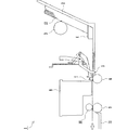
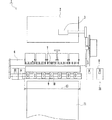
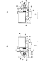
図1は、従来の画像形成装置の構成を示す側面図であり、図2は、従来の画像形成装置の構成を示す平面図である。 FIG. 1 is a side view showing the configuration of a conventional image forming apparatus, and FIG. 2 is a plan view showing the configuration of the conventional image forming apparatus.
従来の画像形成装置1は、記録紙トレイ2、給紙ローラ3、記録紙分離部4、記録紙検出センサ5、プラテンローラ6、記録紙押えローラ7、記録ヘッド8、下流側搬送ローラ9、下流側紙押えローラ10、排紙トレイ11などを備える。
A conventional
記録紙12は、記録紙トレイ2上に積層される。パソコンなどから印刷指示があると、画像形成装置1は、予め設定されたメンテナンス動作を実行した後、記録ヘッド8を所定のホームポジション21から印刷開始位置へ移動させる。次に、記録紙分離部4によって記録紙トレイ2から一枚の記録紙12が分離されて取り出され、この記録紙12は、給紙ローラ3によって記録紙検出センサ5がオンになる位置まで搬送される。
The
その後、記録紙12は、プラテンローラ6に当接するまで所定の距離搬送された後、停止する。次に、図示されていない駆動系によって、給紙ローラ3用の駆動経路がプラテンローラ6用の駆動経路に切り替えられる。記録紙12は、プラテンローラ6と、プラテンローラ6に圧接された記録紙押えローラ7との間に搬送され、その後、プラテンローラ6が回転することによって記録紙12の先端部が印刷開始位置まで搬送された状態で、一旦停止する。
Thereafter, the
記録ヘッド8は、図示されていないキャリアユニットに搭載され、キャリアユニットが移動することで、記録紙12の搬送方向に直交する主走査方向に移動する。記録ヘッド8は、印刷エリア13内を主走査方向に移動しながら、印刷データに基づいてインクを吐出することで画像を形成する。
The
1ライン分の印刷が終わると、記録ヘッド8は所定の待機位置に戻る。次に、プラテンローラ6が回転することによって、記録紙12は、搬送方向即ち副走査方向に正確に1ライン分送られ、停止した状態で、1ライン目と同様に2ライン目の印刷が開始される。
When printing for one line is completed, the
記録紙押えローラ7とプラテンローラ6とは、記録紙12の搬送経路上で互いに対向するように配置され、記録紙12を挟持しながら回転することで記録紙12を搬送する。同様に、下流側紙押えローラ10と下流側搬送ローラ9とは、記録紙12の搬送経路上で互いに対向するように配置され、記録紙12を挟持しながら回転することで記録紙12を搬送する。記録紙押えローラ7、記録ヘッド8、下流側紙押えローラ10は、記録紙12の搬送方向においてこの順に連続して配置される。下流側搬送ローラ9は、プラテンローラ6と同期して回転する。下流側搬送ローラ9と下流側紙押えローラ10との圧接力は、記録紙押えローラ7とプラテンローラ6との圧接力より小さくなるように設定される。
The recording
まず、記録紙12は、プラテンローラ6の回転力によって1ラインずつ搬送され、印刷データに基づいて1ラインずつ印刷されながら副走査方向に搬送される。次に、記録紙12の先端部が下流側搬送ローラ9に到達すると、記録紙12は、プラテンローラ6および下流側搬送ローラ9の両者の回転力によって1ラインずつ副走査方向に搬送され、印刷データに基づいて記録ヘッド8からインクが吐出されることで画像を形成される。
First, the
記録紙12の後端部が記録紙検出センサ5を通過すると、記録紙検出センサ5はオフになり、記録紙検出センサ5のオフ後も記録紙12に対する画像の形成が継続される。この後さらに記録紙に対する画像形成が継続されると、記録紙12の後端部がプラテンローラ6から離間し、それ以後は下流側搬送ローラ9の回転力のみによって記録紙12は搬送される。記録紙12への画像の形成が終了すると、記録紙12は下流側搬送ローラ9によって排紙トレイ11上に排出される。
When the trailing edge of the
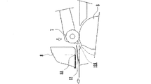
図3及び図4に示すように、上述のような従来の画像形成装置1では、記録紙12の後端がプラテンローラ6から離間する瞬間に、記録紙12の後端が弾き出されることで記録紙12の搬送速度がそれ以前と比べて微妙に変化し、記録紙12の搬送量が狂うという問題がある。記録紙12の搬送量が狂うと、記録ヘッド8のインク吐出口8Aから吐出されたインク液滴の着弾箇所が、正常に搬送された場合の記録紙12Aと、弾き出された記録紙12とで異なることになる。
As shown in FIGS. 3 and 4, in the conventional
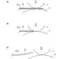
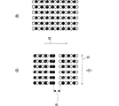
図5(A)は、従来の画像形成装置1によって記録紙上に形成された画像の拡大図であり、図5(B)は、記録紙上に正常に形成された画像の拡大図である。図5(A)及び図5(B)において、黒丸及び白丸は、吐出されたインク液滴のドットを表している。図5(A)及び図5(B)では、説明の便宜上、インク液滴のドットを黒丸と白丸との2種類で表しているが、両者に違いはない。
FIG. 5A is an enlarged view of an image formed on the recording paper by the conventional
図5(B)に示すように、記録紙12が正常に搬送された場合は、印刷データに基づいて記録ヘッド8のインク吐出口8Aからインク液滴が吐出されて、記録紙12上に黒丸と白丸とが交互に整然と印刷されていく。
As shown in FIG. 5B, when the
これに対して、記録紙12の搬送量が狂った場合は、図5(A)に示すように、インク液滴の着弾位置が正規の位置から外れるため、黒丸と白丸とが交互に整然と印刷されない現象が生じ、副走査方向14において黒丸と白丸とが正常距離より離れるか又は重なり合う。このため、記録紙12の主走査方向15に横筋16、または、カラー印刷の場合は色むらが発生する。
On the other hand, when the transport amount of the
このような横筋16または色むらを解消するために、例えば以下のような3つの技術が知られている。
In order to eliminate such
第1に、印刷途中に記録紙の後端がプラテンローラから離間しないように、所定の記録紙サイズよりも副走査方向に長い記録紙を用い、印刷終了後に記録紙の後端の不要部分を切り離すという技術がある。 First, use recording paper that is longer in the sub-scanning direction than the predetermined recording paper size so that the trailing edge of the recording paper is not separated from the platen roller during printing. There is a technology to separate.
また、第2に、記録紙の後端が弾き出されるであろう量の分だけ少なく紙送りする技術がある(例えば、特許文献1参照。)。 Secondly, there is a technique for feeding the paper by an amount that the trailing edge of the recording paper will be ejected (see, for example, Patent Document 1).
さらに、第3に、複数の回動ローラと回動ローラの圧力可変機構とを備えるという技術がある(例えば、特許文献2参照。)。この技術では、例えば、記録紙が頭出しされるまでは回動ローラの圧接力は強くされ、その後、圧接力は弱くされる。これによって、記録紙の先端が、紙ガイドの湾曲面と摺接又は回動ローラの周面に衝突等することにより、記録紙の搬送量が狂うことを抑制できるとしている。
しかし、上述の第1の技術では、所定の記録紙サイズよりも長いものを準備しなければならないうえ、記録紙の不要部分を切り離す作業が必要になり、作業効率が悪い。 However, in the above-described first technique, it is necessary to prepare a paper longer than a predetermined recording paper size, and it is necessary to separate unnecessary portions of the recording paper, resulting in poor work efficiency.
また、第2の技術では、記録紙の質、厚み、表面の摩擦が異なる場合は、搬送量を制御しきれないという問題がある。搬送量を正確に制御できない場合は、記録紙に形成された画像の品質が低下する。 Further, the second technique has a problem that the transport amount cannot be controlled when the quality, thickness, and surface friction of the recording paper are different. If the transport amount cannot be accurately controlled, the quality of the image formed on the recording paper is degraded.
さらに、第3の技術では、記録紙の質、厚み、表面の摩擦が異なる場合は、搬送量を制御しきれず、また、回動ローラを専用モータで駆動するのでコストアップするという問題がある。 Furthermore, in the third technique, when the quality, thickness, and surface friction of the recording paper are different, there is a problem that the conveyance amount cannot be controlled and the rotation roller is driven by a dedicated motor, resulting in an increase in cost.
この発明の目的は、記録媒体に形成された画像の品質を向上できる画像形成装置を提供することにある。 An object of the present invention is to provide an image forming apparatus capable of improving the quality of an image formed on a recording medium.
この発明の他の目的は、低コストで記録媒体の搬送量の狂いを抑制できる画像形成装置を提供することにある。 Another object of the present invention is to provide an image forming apparatus capable of suppressing a deviation in the conveyance amount of a recording medium at low cost.
この発明の画像形成装置は、上述の課題を解決するために以下のように構成される。 The image forming apparatus of the present invention is configured as follows in order to solve the above-described problems.
(1)この発明の画像形成装置は、記録部、上流側搬送部、下流側搬送部、切換部、検出部、及び、制御部を備える。 (1) An image forming apparatus according to the present invention includes a recording unit, an upstream conveyance unit, a downstream conveyance unit, a switching unit, a detection unit, and a control unit.
記録部は、所定の搬送方向に搬送される記録媒体に画像を記録する。 The recording unit records an image on a recording medium conveyed in a predetermined conveyance direction.
上流側搬送部は、記録媒体の搬送方向において記録部の上流側に配置され、記録媒体に圧接する搬送可能位置と記録媒体に接触しない搬送不可能位置との間で少なくとも一部が変位自在にされ、記録媒体との圧接時に記録媒体を搬送する。 The upstream transport unit is arranged on the upstream side of the recording unit in the transport direction of the recording medium, and at least a part of the upstream transport unit is displaceable between a transportable position that is in pressure contact with the recording medium and a non-transportable position that does not contact the recording medium. The recording medium is conveyed at the time of press contact with the recording medium.
下流側搬送部は、搬送方向において記録部の下流側に配置され、記録媒体を搬送する。 The downstream transport unit is disposed downstream of the recording unit in the transport direction and transports the recording medium.
切換部は、上流側搬送部の少なくとも一部を搬送可能位置と搬送不可能位置との間で変位させる。 The switching unit displaces at least a part of the upstream-side transport unit between the transportable position and the untransportable position.
検出部は、搬送方向において上流側搬送部の上流側近傍に記録媒体があるか否かを検出する。 The detection unit detects whether there is a recording medium in the vicinity of the upstream side of the upstream side conveyance unit in the conveyance direction.
制御部は、検出部による検出結果に基づいて、切換部を動作させるタイミングを制御し、記録媒体の後端が上流側搬送部より搬送方向の下流側に搬送される前に、上流側搬送部を搬送可能位置から搬送不可能位置へ向けて変位させる。 The control unit controls the timing for operating the switching unit based on the detection result by the detection unit, and before the rear end of the recording medium is conveyed downstream in the conveyance direction from the upstream conveyance unit, the upstream conveyance unit Is displaced from the transportable position toward the untransportable position.
この構成においては、記録媒体は、上流側搬送部と下流側搬送部とで圧接されながら搬送され、記録媒体の後端が上流側搬送部より搬送方向の下流側に搬送される前に、上流側搬送部が搬送可能位置から搬送不可能位置へ向けて変位する。記録媒体の後端が上流側搬送部に弾き出される前に、上流側搬送部が記録媒体から離間する方向に変位するので、記録媒体の後端の弾き出しが抑制される。したがって、記録媒体の搬送量が正確に制御される。 In this configuration, the recording medium is conveyed while being pressed by the upstream conveyance unit and the downstream conveyance unit, and before the rear end of the recording medium is conveyed downstream from the upstream conveyance unit in the conveyance direction, The side transport unit is displaced from the transportable position toward the untransportable position. Before the rear end of the recording medium is ejected to the upstream transport section, the upstream transport section is displaced in a direction away from the recording medium, so that ejection of the rear end of the recording medium is suppressed. Therefore, the conveyance amount of the recording medium is accurately controlled.
(2)上流側搬送部は、搬送方向の異なる位置に配置された複数の回動ローラを含み、複数の回動ローラは、搬送方向の下流側に配置されたものほど記録媒体に対する圧接力が小さい。 (2) The upstream conveying unit includes a plurality of rotating rollers arranged at different positions in the conveying direction, and the plurality of rotating rollers arranged on the downstream side in the conveying direction has a pressure contact force with respect to the recording medium. small.
この構成においては、搬送方向の下流側に配置された回動ローラほど、記録媒体に対する圧接力が小さいので、記録媒体の後端が弾き出されることによる搬送量の狂いが小さくなる。 In this configuration, the rotation roller disposed on the downstream side in the transport direction has a smaller pressure contact force with respect to the recording medium, and therefore, the deviation in the transport amount due to the trailing edge of the recording medium being ejected is reduced.
(3)切換部は、複数の回動ローラのうち、搬送方向の最も下流側に配置された回動ローラのみを搬送可能位置と搬送不可能位置との間で変位させる。 (3) A switching part displaces only the rotation roller arrange | positioned among the some rotation rollers in the most downstream side of a conveyance direction between a conveyance possible position and a conveyance impossible position.
この構成においては、最も下流側に配置された回動ローラが搬送可能位置と搬送不可能位置との間で変位するので、記録媒体の後端が弾き出されることによる搬送量の狂いが抑制される。また、複数の回動ローラのうち、最も下流側に配置された回動ローラのみを搬送可能位置と搬送不可能位置との間で変位させることで、低コスト化される。 In this configuration, the rotation roller arranged on the most downstream side is displaced between the transportable position and the untransportable position, so that a deviation in the transport amount caused by ejecting the rear end of the recording medium is suppressed. . Further, the cost can be reduced by displacing only the rotation roller arranged on the most downstream side among the plurality of rotation rollers between the transportable position and the untransportable position.
(4)この発明の画像形成装置は、キャリアユニットをさらに備える。キャリアユニットは、記録部を搭載し、搬送方向に直交する主走査方向に移動自在にされる。 (4) The image forming apparatus of the present invention further includes a carrier unit. The carrier unit has a recording unit and is movable in the main scanning direction orthogonal to the transport direction.
切換部は、キャリアユニットが主走査方向へ移動する力を、搬送可能位置から搬送不可能位置へ向けて変位する駆動力として上流側搬送部に伝達する駆動力伝達機構を含む。 The switching unit includes a driving force transmission mechanism that transmits a force for moving the carrier unit in the main scanning direction to the upstream side conveyance unit as a driving force that is displaced from the conveyance possible position toward the conveyance impossible position.
この構成においては、キャリアユニットが主走査方向へ移動する力が伝達されて、上流側搬送部が搬送可能位置から搬送不可能位置へ向けて変位する駆動力として利用される。このため、上流側搬送部を搬送可能位置から搬送不可能位置へ向けて変位させるための駆動源を別に設ける必要がない。 In this configuration, the force by which the carrier unit moves in the main scanning direction is transmitted, and the upstream transport unit is used as a driving force that moves from the transportable position to the untransportable position. For this reason, it is not necessary to provide a separate drive source for displacing the upstream transport unit from the transportable position toward the untransportable position.
(5)制御部は、記録媒体の搬送が停止した状態で、上流側搬送部を搬送可能位置から搬送不可能位置へ向けて変位させる。 (5) The control unit displaces the upstream transport unit from the transportable position toward the untransportable position in a state where the transport of the recording medium is stopped.
この構成においては、上流側搬送部が搬送可能位置から搬送不可能位置へ向けて変位するのは、記録媒体の搬送が停止した状態のときなので、記録媒体の搬送中に上流側搬送部が変位することによる記録媒体の搬送量の狂いが抑制される。 In this configuration, the upstream transport section is displaced from the transportable position toward the untransportable position when the recording medium transport is stopped, so the upstream transport section is displaced during the recording medium transport. This suppresses a deviation in the conveyance amount of the recording medium.
この発明によれば、以下の効果を奏することができる。 According to the present invention, the following effects can be obtained.
(1)記録媒体の後端が上流側搬送部に弾き出される前に、上流側搬送部を記録媒体から離間する方向に変位させることで、記録媒体の搬送量を正確に制御することができ、これによって、記録媒体に形成された画像の品質を向上させることができる。 (1) Before the trailing end of the recording medium is ejected to the upstream side conveyance unit, the upstream side conveyance unit is displaced in a direction away from the recording medium, so that the conveyance amount of the recording medium can be accurately controlled. Thereby, the quality of the image formed on the recording medium can be improved.
(2)搬送方向の下流側に配置された回動ローラほど記録媒体に対する圧接力が小さくなるようにすることで、記録媒体の後端が弾き出されることによる搬送量の狂いを小さくすることができる。これによって、記録媒体に形成された画像の品質をより向上させることができる。 (2) By making the rotating roller arranged on the downstream side in the conveying direction have a smaller pressure contact force with respect to the recording medium, it is possible to reduce the deviation in the conveying amount due to the trailing edge of the recording medium being ejected. . Thereby, the quality of the image formed on the recording medium can be further improved.
(3)低コストで、記録媒体の搬送量を正確に制御することができ、記録媒体に形成された画像の品質を向上させることができる。 (3) The conveyance amount of the recording medium can be accurately controlled at low cost, and the quality of the image formed on the recording medium can be improved.
(4)キャリアユニットが主走査方向へ移動する力を伝達して、上流側搬送部が搬送可能位置から搬送不可能位置へ向けて変位する駆動力として利用することで、別に駆動源を設ける必要がなくなり、低コスト化することができる。 (4) It is necessary to provide a separate drive source by transmitting the force by which the carrier unit moves in the main scanning direction and using it as a driving force that displaces the upstream transport section from the transportable position to the untransportable position. The cost can be reduced.
(5)記録媒体の搬送が停止した状態で、上流側搬送部を搬送可能位置から搬送不可能位置へ向けて変位させることで、記録媒体の搬送量をより正確に制御することができる。 (5) With the conveyance of the recording medium stopped, the conveyance amount of the recording medium can be controlled more accurately by displacing the upstream conveyance section from the conveyance position to the conveyance impossible position.
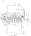
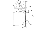
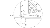
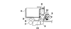
以下に、この発明を実施するための最良の形態について、図面に基づいて説明する。図6は、この発明の実施形態に係る画像形成装置30の概略の構成を示す平面図である。図7は、画像形成装置30の一部の構成を示す右側面図である。
Hereinafter, the best mode for carrying out the present invention will be described with reference to the drawings. FIG. 6 is a plan view showing a schematic configuration of the
画像形成装置30は、記録紙トレイ31、給紙ローラ32、記録紙分離部(不図示)、記録紙検出センサ33、プラテンローラ34、上流側搬送部35、記録ヘッド36、複数の下流側搬送ローラ37、複数の下流側紙押えローラ38、排紙トレイ39、及び、制御部などを備えている。
The
記録紙40は、記録紙トレイ31に収容され、給紙ローラ32によって給紙される。記録紙分離部は、記録紙トレイ31から給紙される記録紙40を1枚ずつに分離する。
The
記録紙検出センサ33は、この発明の検出部に相当する。記録ヘッド36は、この発明の記録部に相当する。下流側紙押えローラ38は、この発明の下流側搬送部に相当する。
The recording
記録紙検出センサ33は、副走査方向51において、上流側搬送部35の上流側近傍に記録紙40があるか否かを検出する。
The recording
上流側搬送部35は、複数の上流側搬送ユニット41,42,43,44,45から構成されている。上流側搬送ユニット41〜45は、主走査方向52においてこの順に配置されている。上流側搬送ユニット41〜45のそれぞれは、互いに同様に構成されている。
The
上流側搬送ユニット43は、記録紙押えローラ43A,43Bと、ホルダ43Cとを有する。記録紙押えローラ43A,43Bのそれぞれは、副走査方向51におけるホルダ43Cの下流側端部に軸支されている。ホルダ43Cは、副走査方向51(記録紙40の搬送方向)における略中央部をフレーム46に軸支されている。このようにして、記録紙押えローラ43A,43Bは、記録紙40に圧接する搬送可能位置と、記録紙40から離間する搬送不可能位置との間で変位自在にされている。
The upstream
ホルダ43Cの上流側端部には、スプリング47の一端が係止され、スプリング47の他端はフレーム46に係止されている。スプリング47によって、ホルダ43Cは、図7において反時計方向の力を付加され、記録紙押えローラ43A,43Bは、下方向の力を付加されている。このため、平常時において記録紙押えローラ43A,43Bは、プラテンローラ34に圧接されている。
One end of the
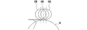
図6及び図8に示すように、上流側搬送ユニット41〜45のそれぞれの記録紙押えローラの中で、記録紙押えローラ43A,43Bが副走査方向において最も下流側に配置され、次いで、記録紙押えローラ42A,42B及び記録紙押えローラ44A,44Bが配置され、記録紙押えローラ41A,41B及び記録紙押えローラ45A,45Bが最も上流側に配置されている。すなわち、図6に示すように、記録紙押えローラ41A,41B,42A,42B,43A,43B,44A,44B,45A,45Bは、平面視において、略V字形を呈するように配置されている。
As shown in FIGS. 6 and 8, among the recording sheet pressing rollers of the upstream
記録紙押えローラ41A,41B,42A,42B,43A,43B,44A,44B,45A,45Bのそれぞれは、プラテンローラ34に対向配置されている。記録紙押えローラ41A,41B,42A,42B,43A,43B,44A,44B,45A,45Bは、副走査方向の下流側に配置されたものほどプラテンローラに対する圧接力を小さくされている。
Each of the recording
上流側搬送部35、記録ヘッド36及び下流側紙押えローラ38は、副走査方向51においてこの順に配置されている。下流側搬送ローラ37と下流側紙押えローラ38とは、互いに対向配置されている。下流側搬送ローラ37と下流側紙押えローラ38との圧接力は、記録紙押えローラ43A,43Bとプラテンローラ34との圧接力より小さくなるように設定されている。
The upstream
記録ヘッド36には、インクカートリッジが着脱自在に装着されている。記録ヘッド36は、キャリアユニット48に搭載され、主走査方向52に移動自在にされている。
An ink cartridge is detachably attached to the
キャリアユニット48は、ラックギヤ49を備えている。主走査方向の第1の端部24側に、連結ギヤ53が配置されている。連結ギヤ53は、副走査方向の上流側端部に傘歯車53Aを備え、下流側端部にワンウェイ歯車53Bを備えている。
The
図9(A)は、画像形成装置30の一部の構成を示す左側面図であり、図9(B)は、画像形成装置30の一部の構成を示す右側面図である。
FIG. 9A is a left side view illustrating a partial configuration of the
キャリアユニット48が第1ポジション22から第2ポジション23へ移動することで、ラックギヤ49がワイウェイ歯車53Bに上方から噛み合い、ワンウェイ歯車53Bが図6における矢印54方向に回転する。
As the
ワンウェイ歯車53Bは、図示されていないワンウェイクラッチを介して連結ギヤ53の軸部に取り付けられている。このため、ワンウェイ歯車53Bは、矢印54方向に回転するとき、傘歯車53Aを矢印54方向に回転させるが、矢印54と反対方向に回転するときは、傘歯車53Aを回転させない。
The one-
また、主走査方向にカムシャフト55が配置されている。カムシャフト55は、両端部のそれぞれをフレームに軸支されている。カムシャフト55は、第1の端部24側に傘歯車55Aを備えており、傘歯車55Aは、連結ギヤ53の傘歯車53Aと噛み合っている。連結ギヤ53が矢印54方向に回転することで、カムシャフト55は、矢印56方向に回転する。
A
カムシャフト55は、中間に円板カム55Bを備えている。図10に示すように、円板カム55Bはホルダ43Cと接触している。カムシャフト55が矢印56方向に回転することで、円板カム55Bがホルダ43Cを矢印56方向に回転させ、記録紙押えローラ43A,43Bが上方に変位する。
The
連結ギヤ53及びカムシャフト55は、駆動力伝達機構を構成する。
The
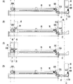
図11は、画像形成装置30の一部の構成を示す説明図であり、図11(A)は、キャリアユニット48がホームポジション21にある状態を示し、図11(B)は、キャリアユニット48が印刷開始位置にある状態を示し、図11(C)は、キャリアユニット48が第1ポジション22と第2ポジション23との間を往復している状態を示し、図11(D)は、キャリアユニット48がホームポジション21へ戻った状態を示す。図12は、図11(D)の右側面図である。
FIG. 11 is an explanatory view showing a part of the configuration of the
カムシャフト55の第2の端部25側に、ねじりスプリング58が挿通されている。ねじりスプリング58の一端はフレームに係止されており、ねじりスプリング58の他端は、カムシャフト55に係止されている。カムシャフト55が矢印56方向に回転すると、カムシャフト55には、ねじりスプリング58によって軸方向の回転を元に戻そうとする力が働く。
A
カムシャフト55は、第2の端部25側に複数の爪部55Cを備えている。また、主走査方向52の第2の端部25側に、ロックレバーホルダ57が配置されている。ロックレバーホルダ57は、ロックレバー57Aを備えており、ロックレバー57Aはロック時に爪部55Cと係合する。ロックレバー57Aが爪部55Cと係合することで、カムシャフト55の矢印56と反対方向への回転がロックされる。
The
爪部55Cのそれぞれは、矢印56方向における下流側の側面が、カムシャフト55の周面に対して下流側に向けて下り傾斜するように形成され、上流側側面がカムシャフト55の周面に対して垂直になるように形成されている。このため、ロックレバー57Aが爪部55Cと係合しているとき、上述のように、カムシャフト55は、矢印56方向へは回転自在にされ、矢印56と反対方向への回転はロックされる。
Each of the
図11(D)に示すように、キャリアユニット48は、突起部48Aを備えている。キャリアユニット48がホームポジションに戻ったとき、キャリアユニット48の突起部48Aがロックレバーホルダ57の傾斜部57Bを押すことで、ロックレバーホルダ57が図11(D)において時計方向に傾き、ロックレバー57Aと爪部55Cとの係合が解除される。これによって、カムシャフト55は、ねじりスプリング58の弾性力によって矢印56と反対方向に回転し、記録紙押えローラ43A,43Bが下方に即ち搬送可能位置に変位し、記録紙40に圧接自在となる。
As shown in FIG. 11D, the
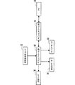
図13は、画像形成装置30の概略の構成を示すブロック図である。
FIG. 13 is a block diagram illustrating a schematic configuration of the
画像形成装置30は、メインコントロール部61及びサブコントロール部62を含む制御部を備えている。サブコントロール部62は、各種のドライバを有する。サブコントロール部62には、キャリアモータ63、紙送りモータ64、記録ヘッド36、記録紙検出センサ33などが接続されている。パソコン65から送信された印刷指示は、メインコントロール部61に入力され、所定の処理が施された後、サブコントロール部62を経由して、キャリアモータ63、紙送りモータ64及び記録ヘッド36に出力される。
The
ラックギヤ49、キャリアモータ63、連結ギヤ53、カムシャフト55及びロックレバーホルダ57は、切換部を構成する。
The
メインコントロール部61は、記録紙検出センサ33による検出結果に基づいて、切換部を動作させるタイミングを制御する。具体的には、メインコントロール部61は、記録紙40の後端が記録紙押えローラ43A,43Bより副走査方向51の下流側に搬送される前に、記録紙押えローラ43A,43Bを搬送可能位置から搬送不可能位置へ向けて変位させる。
The
紙送りモータ64は、プラテンローラ34、下流側搬送ローラ37を駆動する。キャリアモータ63は、キャリアユニット48を主走査方向に移動させる。記録ヘッド36は、インク液滴を吐出する。記録紙検出センサ33は、所定位置において記録紙があるか否かを検出し、サブコントロール部62を介してメインコントロール部61に検出結果を出力する。メインコントロール部61は、検出結果に基づいて、キャリアモータ63を駆動して、記録紙押えローラ43A,43Bを変位させる。
The
つぎに、画像形成装置30の動作について説明する。
Next, the operation of the
記録紙40は、記録紙トレイ31上に積層して収容される。パソコンなどから印刷指示があると、画像形成装置30は、予め設定されたメンテナンス動作を実行した後、記録ヘッド36を所定のホームポジション21から印刷開始位置へ移動させる。次に、図示されていない記録紙分離部によって記録紙トレイ31から一枚の記録紙40が分離されて取り出され、この記録紙40は、給紙ローラ32によって記録紙検出センサ33がオンになる位置まで搬送される。
The
つぎに、記録紙40は、プラテンローラ34に当接するまで所定の距離を搬送された後、停止する。次に、図示されていない駆動系によって、給紙ローラ32用の駆動経路がプラテンローラ34用の駆動経路に切り替えられる。記録紙40は、プラテンローラ34と、プラテンローラ34に圧接された上流側搬送部35との間に搬送され、その後、プラテンローラ34が回転することによって記録紙40の先端部が印刷開始位置まで搬送された状態で、一旦停止する。この実施形態では、印刷開始位置は、記録紙40の搬送方向(副走査方向)において記録ヘッド36によるインク吐出位置より1mm〜1.5mm上流側の位置に設定されている。また、このとき、下流側搬送ローラ37が回転を開始する。
Next, the
記録ヘッド36は、キャリアユニット48が移動することで、主走査方向に移動する。記録ヘッド36は、印刷エリア66内を主走査方向に移動しながら、印刷データに基づいてインクを吐出することで画像を形成する。
The
1ライン分の印刷が終わると、記録ヘッド36は所定の待機位置に戻る。次に、プラテンローラ34が回転することによって、記録紙40は、搬送方向即ち副走査方向に正確に1ライン分送られ、停止した状態で、1ライン目と同様に2ライン目の印刷が開始される。
When printing for one line is completed, the
記録紙40は、プラテンローラ34が回転することによって下流側搬送ローラ37まで1ライン毎に搬送され、印刷データに基づいて印刷されながら副走査方向に搬送される。記録紙40の先端が下流側搬送ローラ37まで到達すると、記録紙40は、プラテンローラ34と下流側搬送ローラ37との両者によって1ライン毎に副走査方向に搬送され、印刷データに基づいて、記録ヘッド36からインクを吐出される。
The
記録紙40の後端が記録紙検出センサ33を通過することで記録紙検出センサ33がOFFされると、メインコントローラ61は、記録紙40の副走査方向の所定位置(記録紙40の後端が、下流側から2番目の位置に配置された記録紙押えローラ42A,42B,44A,44Bから離れた位置)まで印刷を行い、記録紙40の搬送を停止させる。
When the recording
つぎに、メインコントローラ61は、キャリアユニット48を第1ポジション22に移動させる。このとき、記録紙40の後端部は、プラテンローラ34と記録紙押えローラ43A,43Bとによってのみ保持された状態となっている。
Next, the
メインコントローラ61は、キャリアユニット48を第1ポジション22から第2ポジション23へ移動させることで、ラックギヤ49をワイウェイ歯車53Bに噛み合わせ、ワンウェイ歯車53Bを図6における矢印54方向に回転させ、カムシャフト55を矢印56方向に回転させる。
The
カムシャフト55を矢印56方向に回転させることで、円板カム55Bがホルダ43Cを矢印56方向に回転させ、ロックレバー57Aが爪部55Cと係合することで、カムシャフト55の矢印56と反対方向への回転がロックされる。
By rotating the
キャリアユニット48を再度第1ポジション22まで移動させ、第1ポジション22から第2ポジション23へのキャリアユニット48の移動を合計で例えば3回程度行わせる。これによって、記録紙押えローラ43A,43Bが上方に変位し、記録紙押えローラ43A,43Bは、搬送不可能位置まで変位する。このため、記録紙押えローラ43A,43Bは、記録紙40から離間し、記録紙40に圧接しなくなる。
The
記録紙押えローラ43A,43Bを搬送可能位置から搬送不可能位置へ向けて変位させるので、記録紙40の搬送が停止した状態で行われる。
Since the recording
そして、メインコントローラ61は、再び印刷データに基づいて、記録紙40の後端まで記録紙40を搬送して印刷を行い、印刷を終了する。
Then, the
その後、ホルダ43C、記録紙押えローラ43A,43Bを搬送可能位置に戻すためには、キャリアユニット48をホームポジション21へ戻すことによって、ロックレバーホルダ57を回転させ、ロックレバー57Aと爪部55Cとの係合を解除することで、ねじりスプリング58によってカムシャフト55を初期回転位置に戻す。これによって、ホルダ43C、記録紙押えローラ43A,43Bも、搬送可能位置に戻される。
Thereafter, in order to return the
記録紙40への画像の形成が終了すると、記録紙40は下流側搬送ローラ37によって排紙トレイ39上に排出される。
When the formation of the image on the
画像形成装置30によれば、上述のように、副走査方向51において、記録紙40の後端が、プラテンローラ34及び記録紙押えローラ43A,43Bとで挟持される位置より下流側に搬送されるより前に、記録紙押えローラ43A,43Bが記録紙40から離間する搬送不可能位置へ変位するので、記録紙40の後端がプラテンローラ34及び記録紙押えローラ43A,43Bから離れる瞬間に生じやすい記録紙40の搬送ムラが抑制される。このため、記録紙40の搬送量を正確に制御することができ、これによって、記録紙40に形成された画像の品質を向上させることができる。
According to the
また、画像形成装置30によれば、図5(B)に示すように、記録紙40に吐出されたインク液滴のドットを表す黒丸と白丸とが整然と配列され、高品質な画像を記録紙40に形成することができる。
Further, according to the
さらに、キャリアユニット48が主走査方向へ移動する力を伝達させて、記録紙押えローラ43A,43Bが搬送可能位置から搬送不可能位置へ向けて変位する駆動力として利用することで、別に駆動源を設ける必要がなくなり、低コスト化を図ることができる。
Further, a force for moving the
また、記録紙40の搬送が停止した状態で、記録紙押えローラ43A,43Bを搬送可能位置から搬送不可能位置へ向けて変位させることで、記録紙40の搬送量をより正確に制御することができる。
Further, the conveyance amount of the
なお、円板カム55Bによって搬送可能位置と搬送不可能位置との間で変位させるのは、記録紙押えローラ43A,43Bのみでなく、他の記録紙押えローラ41A,41B,42A,42B,44A,44B,45A,45Bも変位させるように構成してもよい。
The
また、搬送不可能位置は、記録紙40から離間する位置でなくとも、記録紙40への圧接力が、搬送可能位置より弱まる位置であれば、搬送ムラは抑制される。
Further, even if the conveyance impossible position is not a position away from the
最後に、上述の実施形態の説明は、すべての点で例示であって、制限的なものではないと考えられるべきである。本発明の範囲は、上述の実施形態ではなく、特許請求の範囲によって示される。さらに、本発明の範囲には、特許請求の範囲と均等の意味および範囲内でのすべての変更が含まれることが意図される。 Finally, the description of the above-described embodiment is to be considered in all respects as illustrative and not restrictive. The scope of the present invention is shown not by the above embodiments but by the claims. Furthermore, the scope of the present invention is intended to include all modifications within the meaning and scope equivalent to the scope of the claims.
30 画像形成装置
33 記録紙検出センサ
34 プラテンローラ
35 上流側搬送部
36 記録ヘッド
37 下流側搬送ローラ
38 下流側紙押えローラ(下流側搬送部)
40 記録紙(記録媒体)
43A,43B 記録紙押えローラ
43C ホルダ
47 スプリング
48 キャリアユニット
49 ラックギヤ
51 副走査方向
52 主走査方向
53 連結ギヤ
53A 傘歯車
53B ワンウェイギヤ
55 カムシャフト
55A 傘歯車
55B 円板カム
58 ねじりスプリング
61 メインコントローラ(制御部)
62 サブコントローラ(制御部)
40 Recording paper (recording medium)
43A, 43B Recording
62 Sub-controller (control unit)
Claims (5)
前記記録媒体の搬送方向において前記記録部の上流側に配置され、前記記録媒体に圧接する搬送可能位置と前記記録媒体に接触しない搬送不可能位置との間で少なくとも一部が変位自在にされ、前記記録媒体との圧接時に前記記録媒体を搬送する上流側搬送部と、
前記搬送方向において前記記録部の下流側に配置され、前記記録媒体を搬送する下流側搬送部と、
前記上流側搬送部の少なくとも一部を前記搬送可能位置と前記搬送不可能位置との間で変位させる切換部と、
前記搬送方向において前記上流側搬送部の上流側近傍に前記記録媒体があるか否かを検出する検出部と、
前記検出部による検出結果に基づいて、前記切換部を動作させるタイミングを制御する制御部と、を備え、
前記制御部は、前記記録媒体の後端が前記上流側搬送部より前記搬送方向の下流側に搬送される前に、前記上流側搬送部を前記搬送可能位置から前記搬送不可能位置へ向けて変位させることを特徴とする画像形成装置。 A recording unit for recording an image on a recording medium conveyed in a predetermined conveyance direction;
Arranged at the upstream side of the recording unit in the conveyance direction of the recording medium, and at least partly displaceable between a transportable position that is in pressure contact with the recording medium and a non-transportable position that does not contact the recording medium; An upstream side conveyance unit for conveying the recording medium at the time of pressure contact with the recording medium;
A downstream transport unit that is disposed downstream of the recording unit in the transport direction and transports the recording medium;
A switching unit that displaces at least a part of the upstream-side transport unit between the transportable position and the non-transportable position;
A detection unit that detects whether or not the recording medium is in the vicinity of the upstream side of the upstream side conveyance unit in the conveyance direction;
A control unit that controls the timing of operating the switching unit based on the detection result by the detection unit;
The control unit moves the upstream transport unit from the transportable position to the untransportable position before the trailing end of the recording medium is transported downstream from the upstream transport unit in the transport direction. An image forming apparatus that is displaced.
前記切換部は、前記キャリアユニットが前記主走査方向へ移動する力を、前記搬送可能位置から前記搬送不可能位置へ向けて変位する駆動力として前記上流側搬送部に伝達する駆動力伝達機構を含むことを特徴とする請求項1から3のいずれかに記載の画像形成装置。 A carrier unit mounted with the recording unit and movable in a main scanning direction orthogonal to the transport direction;
The switching unit includes a driving force transmission mechanism that transmits a force that moves the carrier unit in the main scanning direction to the upstream transport unit as a driving force that is displaced from the transportable position toward the non-transportable position. The image forming apparatus according to claim 1, wherein the image forming apparatus includes the image forming apparatus.
Priority Applications (1)
| Application Number | Priority Date | Filing Date | Title |
|---|---|---|---|
| JP2006013653A JP2007190889A (en) | 2006-01-23 | 2006-01-23 | Image forming apparatus |
Applications Claiming Priority (1)
| Application Number | Priority Date | Filing Date | Title |
|---|---|---|---|
| JP2006013653A JP2007190889A (en) | 2006-01-23 | 2006-01-23 | Image forming apparatus |
Publications (1)
| Publication Number | Publication Date |
|---|---|
| JP2007190889A true JP2007190889A (en) | 2007-08-02 |
Family
ID=38446936
Family Applications (1)
| Application Number | Title | Priority Date | Filing Date |
|---|---|---|---|
| JP2006013653A Pending JP2007190889A (en) | 2006-01-23 | 2006-01-23 | Image forming apparatus |
Country Status (1)
| Country | Link |
|---|---|
| JP (1) | JP2007190889A (en) |
Cited By (1)
| Publication number | Priority date | Publication date | Assignee | Title |
|---|---|---|---|---|
| CN102951467A (en) * | 2011-08-09 | 2013-03-06 | 冲电气工业株式会社 | Recording medium conveying mechanism and recording medium processing device |
-
2006
- 2006-01-23 JP JP2006013653A patent/JP2007190889A/en active Pending
Cited By (2)
| Publication number | Priority date | Publication date | Assignee | Title |
|---|---|---|---|---|
| CN102951467A (en) * | 2011-08-09 | 2013-03-06 | 冲电气工业株式会社 | Recording medium conveying mechanism and recording medium processing device |
| CN102951467B (en) * | 2011-08-09 | 2015-05-27 | 冲电气工业株式会社 | Recording medium conveying mechanism and recording medium processing device |
Similar Documents
| Publication | Publication Date | Title |
|---|---|---|
| US6523929B2 (en) | Image forming apparatus | |
| JP5159212B2 (en) | Inkjet recording device | |
| US7533962B2 (en) | Ink jet printing apparatus and ink jet printing method | |
| US7527371B2 (en) | Ink jet printing apparatus and method for controlling ink jet printing apparatus | |
| CN101092088A (en) | Paper shift apparatus and array ink-jet printer having the same and array printer printing method | |
| CN102673130B (en) | A method of printing continuous paper using a line printer and the line printer | |
| JP3762228B2 (en) | Recording apparatus and recording method | |
| JP3347498B2 (en) | Recording device | |
| US6991387B2 (en) | Printing apparatus and printing position adjustment method | |
| JP3228476B2 (en) | Recording device | |
| JP2007203546A (en) | Recording apparatus control method and recording apparatus | |
| JP2007190889A (en) | Image forming apparatus | |
| JP2009083351A (en) | Inkjet recording device | |
| JP2001322324A (en) | Card printing equipment | |
| US7677719B2 (en) | Inkjet recording apparatus | |
| JP2006334810A (en) | Inkjet recording device | |
| JP2003237163A (en) | Image forming device | |
| JPH07276736A (en) | Recording device | |
| JP2003320662A (en) | Image forming device | |
| JP2006044060A (en) | Recording device | |
| JP2009262381A (en) | Controller, printing apparatus, method for controlling controller, and controlling program for controller | |
| JP2002192713A (en) | Ink jet recording method and ink jet recording apparatus | |
| JP2007160560A (en) | Inkjet recording device | |
| JP3584120B2 (en) | Printer | |
| JP4240088B2 (en) | Inkjet recording device |