JP2007192090A - 内燃機関の排気還流装置 - Google Patents
内燃機関の排気還流装置 Download PDFInfo
- Publication number
- JP2007192090A JP2007192090A JP2006010123A JP2006010123A JP2007192090A JP 2007192090 A JP2007192090 A JP 2007192090A JP 2006010123 A JP2006010123 A JP 2006010123A JP 2006010123 A JP2006010123 A JP 2006010123A JP 2007192090 A JP2007192090 A JP 2007192090A
- Authority
- JP
- Japan
- Prior art keywords
- passage
- exhaust gas
- gas recirculation
- bypass
- combustion engine
- Prior art date
- Legal status (The legal status is an assumption and is not a legal conclusion. Google has not performed a legal analysis and makes no representation as to the accuracy of the status listed.)
- Granted
Links
Images


Classifications
-
- Y—GENERAL TAGGING OF NEW TECHNOLOGICAL DEVELOPMENTS; GENERAL TAGGING OF CROSS-SECTIONAL TECHNOLOGIES SPANNING OVER SEVERAL SECTIONS OF THE IPC; TECHNICAL SUBJECTS COVERED BY FORMER USPC CROSS-REFERENCE ART COLLECTIONS [XRACs] AND DIGESTS
- Y02—TECHNOLOGIES OR APPLICATIONS FOR MITIGATION OR ADAPTATION AGAINST CLIMATE CHANGE
- Y02T—CLIMATE CHANGE MITIGATION TECHNOLOGIES RELATED TO TRANSPORTATION
- Y02T10/00—Road transport of goods or passengers
- Y02T10/10—Internal combustion engine [ICE] based vehicles
- Y02T10/12—Improving ICE efficiencies
Landscapes
- Exhaust-Gas Circulating Devices (AREA)
Abstract
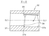
【解決手段】排気還流通路の一部を構成する第1通路37a及びバイパス通路の一部を構成する第2通路37bのそれぞれに一つずつ配置されて通路を開閉する弁体38と、弁体38が一体回転可能に取付けられるとともに、第1通路37a及び第2通路37bのそれぞれを横切るように延びて一端がハウジング37の外部に露出する弁軸39と、を有し、その弁軸39は第1通路37a及び第2通路37bの中心線よりも鉛直上方に偏るように配置されている。
【選択図】図3
Description
2 排気還流通路
3 冷却ユニット
101 吸気系
31 本体部
32 通路切替部(通路切替手段)
33 隔壁
36 熱交換器(冷却手段)
35 通路(バイパス通路)
37 ハウジング
37a 第1通路
37b 第2通路
38 弁体
39 弁軸
CL1 中心線
Claims (3)
- 内燃機関の排気の一部を吸気系に導入する排気還流通路と、前記排気還流通路に設けられた冷却手段と、前記冷却手段を迂回するバイパス通路と、前記排気還流通路を開放する一方で前記バイパス通路を閉鎖する通過位置と前記排気還流通路を閉鎖する一方で前記バイパス通路を開放する迂回位置との間で切替え可能な通路切替手段と、を備え、
前記通路切替手段は、前記排気還流通路の一部を構成し鉛直方向と交差する方向に延びる第1通路と前記バイパス通路の一部を構成し鉛直方向と交差する方向に延びる第2通路とが形成されたハウジングと、前記第1通路及び前記第2通路のそれぞれに設けられて各通路を開閉する弁体と、前記弁体が一体回転可能に取付けられるとともに前記第1通路及び前記第2通路のそれぞれを横切るように延びて一端が前記ハウジングの外部に露出する弁軸と、を有し、
前記弁軸は、前記第1通路及び前記第2通路の中心線よりも鉛直上方に偏るように配置されていることを特徴とする内燃機関の排気還流装置。 - 前記弁軸は、前記第1通路及び前記第2通路の鉛直上方に位置する上端部に配置されていることを特徴とする請求項1に記載の内燃機関の排気還流装置。
- 前記排気還流通路を前記冷却手段が配置された通路と前記バイパス通路とに区分する隔壁を有した筒状の本体部に前記切替手段が接続された冷却ユニットを備え、前記冷却ユニットは前記切替手段が接続された側よりもその反対側が鉛直下方に位置するように傾斜して配置されていることを特徴とする請求項1又は2に記載の内燃機関の排気還流装置。
Priority Applications (1)
| Application Number | Priority Date | Filing Date | Title |
|---|---|---|---|
| JP2006010123A JP4631715B2 (ja) | 2006-01-18 | 2006-01-18 | 内燃機関の排気還流装置 |
Applications Claiming Priority (1)
| Application Number | Priority Date | Filing Date | Title |
|---|---|---|---|
| JP2006010123A JP4631715B2 (ja) | 2006-01-18 | 2006-01-18 | 内燃機関の排気還流装置 |
Publications (2)
| Publication Number | Publication Date |
|---|---|
| JP2007192090A true JP2007192090A (ja) | 2007-08-02 |
| JP4631715B2 JP4631715B2 (ja) | 2011-02-16 |
Family
ID=38447993
Family Applications (1)
| Application Number | Title | Priority Date | Filing Date |
|---|---|---|---|
| JP2006010123A Expired - Fee Related JP4631715B2 (ja) | 2006-01-18 | 2006-01-18 | 内燃機関の排気還流装置 |
Country Status (1)
| Country | Link |
|---|---|
| JP (1) | JP4631715B2 (ja) |
Cited By (1)
| Publication number | Priority date | Publication date | Assignee | Title |
|---|---|---|---|---|
| JP2019007461A (ja) * | 2017-06-28 | 2019-01-17 | 愛三工業株式会社 | Egrクーラバイパスバルブ |
Citations (2)
| Publication number | Priority date | Publication date | Assignee | Title |
|---|---|---|---|---|
| JPH09228902A (ja) * | 1996-02-23 | 1997-09-02 | Fuji Heavy Ind Ltd | エンジンの排気還流装置 |
| JP2005273564A (ja) * | 2004-03-25 | 2005-10-06 | Denso Corp | 排気ガス再循環装置 |
-
2006
- 2006-01-18 JP JP2006010123A patent/JP4631715B2/ja not_active Expired - Fee Related
Patent Citations (2)
| Publication number | Priority date | Publication date | Assignee | Title |
|---|---|---|---|---|
| JPH09228902A (ja) * | 1996-02-23 | 1997-09-02 | Fuji Heavy Ind Ltd | エンジンの排気還流装置 |
| JP2005273564A (ja) * | 2004-03-25 | 2005-10-06 | Denso Corp | 排気ガス再循環装置 |
Cited By (1)
| Publication number | Priority date | Publication date | Assignee | Title |
|---|---|---|---|---|
| JP2019007461A (ja) * | 2017-06-28 | 2019-01-17 | 愛三工業株式会社 | Egrクーラバイパスバルブ |
Also Published As
| Publication number | Publication date |
|---|---|
| JP4631715B2 (ja) | 2011-02-16 |
Similar Documents
| Publication | Publication Date | Title |
|---|---|---|
| US8733327B2 (en) | Charge air duct for an internal combustion engine | |
| JP5001752B2 (ja) | Egrクーラバイパス切替システム | |
| JP6357038B2 (ja) | マルチ流量制御バルブを有するエンジン | |
| JP5862620B2 (ja) | 内燃機関の吸気装置 | |
| EP2310658B1 (en) | Bypass valve having egr valve | |
| JP4728195B2 (ja) | エンジンの吸気制御装置 | |
| JP4631718B2 (ja) | 内燃機関の排気還流装置 | |
| JP4631715B2 (ja) | 内燃機関の排気還流装置 | |
| JP2010024872A (ja) | 流路切替弁 | |
| KR20100064977A (ko) | 자동차용 인터쿨러 어셈블리 | |
| JP2006037773A (ja) | 排気ガス再循環制御装置 | |
| JP5997810B1 (ja) | エンジンの吸気構造 | |
| JP4974835B2 (ja) | 排気ガス再循環装置 | |
| JP5498988B2 (ja) | 熱回収器組立体及び排熱回収装置 | |
| JP5550503B2 (ja) | エンジンの排ガス再循環装置 | |
| JP4949402B2 (ja) | 再循環ガスを分配する装置及び前記装置を備える再循環ガス冷却装置 | |
| KR20100058960A (ko) | 배기 가스 재순환용 쿨러 | |
| EP2481908A1 (en) | Exhaust gas recirculation system | |
| JP5541247B2 (ja) | 内燃機関用バタフライバルブ装置 | |
| JP2007247555A (ja) | 排気熱回収装置 | |
| JP4324967B2 (ja) | 排気ガス再循環制御装置 | |
| JP2007100665A (ja) | 内燃機関の排気通路構造 | |
| CN106168155A (zh) | 内燃机 | |
| JP2005320980A (ja) | 還流ガスの冷却機構 | |
| JP2009156115A (ja) | 排気ガス再循環装置 |
Legal Events
| Date | Code | Title | Description |
|---|---|---|---|
| A621 | Written request for application examination |
Free format text: JAPANESE INTERMEDIATE CODE: A621 Effective date: 20080303 |
|
| A131 | Notification of reasons for refusal |
Free format text: JAPANESE INTERMEDIATE CODE: A131 Effective date: 20100615 |
|
| A521 | Request for written amendment filed |
Free format text: JAPANESE INTERMEDIATE CODE: A523 Effective date: 20100802 |
|
| TRDD | Decision of grant or rejection written | ||
| A01 | Written decision to grant a patent or to grant a registration (utility model) |
Free format text: JAPANESE INTERMEDIATE CODE: A01 Effective date: 20101019 |
|
| A01 | Written decision to grant a patent or to grant a registration (utility model) |
Free format text: JAPANESE INTERMEDIATE CODE: A01 |
|
| A61 | First payment of annual fees (during grant procedure) |
Free format text: JAPANESE INTERMEDIATE CODE: A61 Effective date: 20101101 |
|
| FPAY | Renewal fee payment (event date is renewal date of database) |
Free format text: PAYMENT UNTIL: 20131126 Year of fee payment: 3 |
|
| LAPS | Cancellation because of no payment of annual fees |