JP2007192545A - High frequency heating device - Google Patents
High frequency heating device Download PDFInfo
- Publication number
- JP2007192545A JP2007192545A JP2007117412A JP2007117412A JP2007192545A JP 2007192545 A JP2007192545 A JP 2007192545A JP 2007117412 A JP2007117412 A JP 2007117412A JP 2007117412 A JP2007117412 A JP 2007117412A JP 2007192545 A JP2007192545 A JP 2007192545A
- Authority
- JP
- Japan
- Prior art keywords
- frequency heating
- power supply
- heating device
- cooling air
- voltage
- Prior art date
- Legal status (The legal status is an assumption and is not a legal conclusion. Google has not performed a legal analysis and makes no representation as to the accuracy of the status listed.)
- Granted
Links
Images

Landscapes
- Electric Ovens (AREA)
Abstract
【課題】電子レンジ等のマグネトロンを備えた機器に用いられる高周波加熱装置において、冷却効率の良い電源ユニットを備えた高周波加熱装置を得る。
【解決手段】単方向電源部1の出力電流を測定するために用いるシャント抵抗30は、前記基板32上を流れる冷却風の風路に沿って該基板32上に配置されるとともに前記ダイオードブリッジ及び前記スイッチング素子と略同一直線状に配置される。
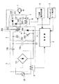
【選択図】図1In a high-frequency heating device used in a device equipped with a magnetron such as a microwave oven, a high-frequency heating device including a power supply unit with good cooling efficiency is obtained.
A shunt resistor (30) used for measuring an output current of a unidirectional power supply unit (1) is disposed on a substrate (32) along a wind path of cooling air flowing on the substrate (32), and the diode bridge and The switching elements are arranged in substantially the same straight line.
[Selection] Figure 1
Description
本発明は、電子レンジ等のマグネトロンを備えた機器に用いて好適な高周波加熱装置に関する。 The present invention relates to a high-frequency heating apparatus suitable for use in equipment equipped with a magnetron such as a microwave oven.
従来、上述した高周波加熱装置には、商用電源が入力される入力側の電流をカレントトランスにて検出し、当該入力電流が所定値になるようにパルス幅制御することでマグネトロンの電磁波出力を一定に制御する構成を採ったもの(例えば、特許文献1参照)や、高圧回路の昇圧トランスの二次側電流をカレントトランスにて検出し、入力電流を一定に制御する構成を採ったものが提案されている(例えば、特許文献2参照)。これらの高周波加熱装置においては、いずれも検出対象である電流をカレントトランスによって検出するようにしている。
なお、従来の高周波加熱装置には、整流して定電圧化した後の商用電源を所定電圧まで電圧降下させるためのセメント抵抗(巻線抵抗の一種)を備えたものもある。
Conventionally, in the above-described high-frequency heating apparatus, the current on the input side to which the commercial power is input is detected by a current transformer, and the electromagnetic wave output of the magnetron is constant by controlling the pulse width so that the input current becomes a predetermined value. Proposals have been made to adopt a configuration in which the current is controlled (for example, see Patent Document 1), or a configuration in which the secondary current of the step-up transformer of the high-voltage circuit is detected by the current transformer and the input current is controlled to be constant. (For example, refer to Patent Document 2). In these high-frequency heating devices, the current to be detected is detected by a current transformer.
Note that some conventional high-frequency heating devices include a cement resistor (a kind of winding resistance) for reducing the voltage of a commercial power supply after rectification and constant voltage to a predetermined voltage.
図6は、上記の特許文献2で開示された高周波加熱装置の構成を示す回路図である。この図に示す高周波加熱装置は、単方向電源部1と、インバータ部2と、高圧整流回路3と、マグネトロン4と、スイッチングレート検出部5と、二次側電流検出部6と、制御部7と、カレントトランス8,9とから構成されている。
FIG. 6 is a circuit diagram showing the configuration of the high-frequency heating device disclosed in Patent Document 2 above. The high-frequency heating device shown in this figure includes a unidirectional power supply unit 1, an inverter unit 2, a high voltage rectifier circuit 3, a magnetron 4, a switching
単方向電源部1は、商用電源20からの交流電源を全波整流するダイオードブリッジ1
01と、チョークコイル102及びコンデンサ103よりなるローパスフィルタ回路とから構成される。また単方向電源部1には、上述したカレントトランス8がダイオードブリッジ101の交流入力側に介挿されており、入力電流の検出に用いられる。インバータ部2は、共振コンデンサ201と、昇圧トランス202と、トランジスタ203と、転流ダイオード204とから構成される。トランジスタ203は、制御部7より与えられる20〜50kHzのスイッチング制御信号によってスイッチング動作する。これにより、昇圧トランス202の一次巻線には高周波電圧が発生する。
The unidirectional power supply unit 1 is a diode bridge 1 that full-wave rectifies an AC power supply from a
01 and a low-pass filter circuit comprising a
なお、トランジスタ203は、主に転流ダイオード204と一体に形成されて、IGBT(Insulated Gate Bipolar Transistor)と呼ばれている。
The
高圧整流回路3は、コンデンサ301及び302と、ダイオード303及び304とから構成されており、昇圧トランス202の二次巻線で発生した電圧を半波倍電圧整流することで高圧直流電圧を発生しマグネトロン4に印加する。マグネトロン4には昇圧トランス202のヒータ巻線からヒータ用の交流電圧も印加される。マグネトロン4は、ヒータ用の交流電圧が印加されることで陰極が傍熱されてエミッション可能な状態となり、この状態で高圧直流電圧が印加されると電磁波エネルギーを発生する。高圧整流回路3には上述したカレントトランス9がダイオード303のカソードと接地との間に介挿されており、二次電流の検出に用いられる。
The high-voltage rectifier circuit 3 includes
スイッチングレート検出部5は、インバータ部3のトランジスタ203のオン/オフデューティ比を検出し、その結果を制御部7に入力する。二次側電流検出部6は、二次電流を全波整流してその平均値を検出し、その結果を制御部7に入力する。制御部7は、スイッチングレート検出部5の出力信号と二次側電流検出部6の出力信号を乗算処理して、乗算値が所望の値になるようにインバータ部3のトランジスタのオン/オフ制御を行う。
The switching
このように、単方向電源部1で商用電源20を単方向電圧に変換し、それをインバータ21で高周波電圧に変換して昇圧トランス202で昇圧した後、再度高圧整流回路3で倍電圧整流して高圧の直流電圧に変換し、マグネトロン4を駆動する。
In this way, the
なお、特許文献2の高周波加熱装置では上述したセメント抵抗についての記載は見当たらないが、もしこれが使用される場合は単方向電源部1の直流出力端と接続先の回路(例えばスイッチングレート検出部5、二次側電流検出部6、制御部7)の電源端子との間に介挿されて、商用電源20を所定電圧に電圧降下させて上記各回路に供給する。
しかしながら、従来の高周波加熱装置においては、次のような問題がある。 However, the conventional high frequency heating apparatus has the following problems.
すなわち、冷却ファンを用いてプリント基板上のダイオードブリッジ101や昇圧トランス202の他、トランジスタ203と転流ダイオード204とが一体形成されてなるIGBTに対する発熱対策を行っているが、形状の大きなカレントトランス8及び9が冷却風の流れを阻害したり、セメント抵抗が発熱源となったりすることもあって、十分な冷却効率が得られてはいなかった。特に、高周波加熱装置本体の小型化に伴ってプリント基板上の限られたスペースに全部品を配置しなければならないことから、冷却効率の向上が望まれている。
In other words, a cooling fan is used to take measures against heat generation of the IGBT in which the
本発明は係る点に鑑みてなされたもので、冷却効率の良い電源ユニットを備えた高周波加熱装置を提供することを目的とする。 This invention is made | formed in view of the point which concerns, and it aims at providing the high frequency heating apparatus provided with the power supply unit with sufficient cooling efficiency.
前記課題を解決するために本発明に係る発明の高周波加熱装置は、少なくとも基板上に、商用電源をダイオードブリッジを用いて単方向に変換する単方向電源部と、少なくとも1個の半導体スイッチング素子を有し、この半導体スイッチング素子をオン/オフすることにより前記単方向電源部からの電力を高周波電力に変換するインバータ部と、前記インバータ部の出力電圧を昇圧する昇圧トランスと、前記昇圧トランスの出力電圧を倍電圧整流する高圧整流部と、を有する高周波加熱装置において、前記単方向電源部の出力電流を測定できる箇所に対して直列に介挿されるシャント抵抗を有し、前記シャント抵抗は、前記基板上を流れる冷却風の風路に沿って該基板上に配置されるとともに前記ダイオードブリッジ及び前記スイッチング素子と略同一直線状に配置されることを特徴とする。 In order to solve the above-described problems, a high-frequency heating device according to the present invention includes a unidirectional power supply unit that converts a commercial power supply in a unidirectional manner using a diode bridge and at least one semiconductor switching element on at least a substrate. An inverter unit that converts power from the unidirectional power source unit to high-frequency power by turning on / off the semiconductor switching element, a step-up transformer that boosts the output voltage of the inverter unit, and an output of the step-up transformer In a high-frequency heating device having a high-voltage rectifying unit that doubles the voltage, the shunt resistor is inserted in series with respect to a location where the output current of the unidirectional power supply unit can be measured. The diode bridge and the switching element are disposed on the board along the air path of the cooling air flowing on the board. Characterized in that it is disposed substantially on the same straight line when.
この構成によれば、形状が一般的に大きいカレントトランスに代えて単方向電源部の出力電流を測定するために用いるシャント抵抗を、プリント基板上を流れる冷却風の風路に沿って該プリント基板上に配置するので、カレントトランスに比べ、シャント抵抗が冷却風の流れを阻害する割合を最小限に抑えることができて、冷却効率の向上が図れる。 According to this configuration, the shunt resistor used for measuring the output current of the unidirectional power supply unit instead of the current transformer having a generally large shape is provided along the air path of the cooling air flowing on the printed circuit board. Since it is disposed above, the rate at which the shunt resistance hinders the flow of the cooling air can be minimized as compared with the current transformer, and the cooling efficiency can be improved.
また、本発明の高周波加熱装置は、上記記載の発明のいずれかに係る発明の高周波加熱装置において、商用電源を所定電圧に電圧降下させるためのセメント抵抗が前記冷却風の風路に対し略交差する方向に配置されるものとしても良い。 The high-frequency heating device according to the present invention is the high-frequency heating device according to any one of the above-described inventions, wherein a cement resistance for dropping the commercial power supply to a predetermined voltage substantially intersects the cooling air flow path. It is good also as what is arrange | positioned in the direction to do.
この構成によれば、発熱を伴うセメント抵抗が冷却風の風路に対し略交差する方向に配置されるので、セメント抵抗を効率良く冷却することが可能となる。 According to this configuration, since the cement resistance accompanied by heat generation is arranged in a direction substantially intersecting the cooling air flow path, the cement resistance can be efficiently cooled.
本発明に係る高周波加熱装置によれば、単方向電源部の出力電流を測定するために用いるシャント抵抗は、プリント基板上を流れる冷却風の風路に沿って該プリント基板上に配置されるので、冷却風の流れを阻害する割合を最小限にして、冷却効率の向上が図れる。 According to the high-frequency heating device according to the present invention, the shunt resistor used for measuring the output current of the unidirectional power supply unit is arranged on the printed circuit board along the air path of the cooling air flowing on the printed circuit board. The efficiency of cooling can be improved by minimizing the rate of obstructing the flow of cooling air.
以下、本発明の実施の形態について、図面を参照しながら詳細に説明する。
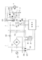
図1は、本発明の一実施の形態に係る高周波加熱装置の構成を示す回路図である。
なお、この図において前述した図5と共通する部分には同一の符号を付けてその説明を省略する。
Hereinafter, embodiments of the present invention will be described in detail with reference to the drawings.
FIG. 1 is a circuit diagram showing a configuration of a high-frequency heating device according to an embodiment of the present invention.
In this figure, parts common to those in FIG. 5 described above are denoted by the same reference numerals and description thereof is omitted.
図1に示すように、本実施の形態の高周波加熱装置は、従来のカレントトランスに代わる入力電流検出手段として、入力電流を検出するためのシャント抵抗30と、このシャント抵抗30に発生する電圧を取り出すためのバッファ31とを具備している。また、本実施の形態の高周波加熱装置には、単方向電源部1の直流出力端と制御部7の電源端子との間に単方向電源部1の直流出力を所定電圧に電圧降下させるためのセメント抵抗50が設けられている。
As shown in FIG. 1, the high-frequency heating device according to the present embodiment has a
シャント抵抗30は、単方向電源部1のダイオードブリッジ101の負出力側端子に対して直列に介挿される。シャント抵抗30のプリント基板への実装に際しては、冷却風の流れを妨げないように、プリント基板上を流れる冷却風の風路に沿って配置される。なお、シャント抵抗30としては、放熱板に取り付ける型のものやセメントモールド型のもの、あるいは裸抵抗線などがある。特に裸抵抗線を用いた場合は省スペース化とコストダウンが図れる。
一方、セメント抵抗50は、上述したように単方向電源部1の直流出力端と制御部7の電源端子との間に介挿される。この場合、プリント基板への実装に際しては、発熱を効果的に冷却するために冷却風の風路に対し略交差する方向に配置される。
The
On the other hand, the
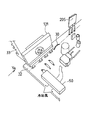
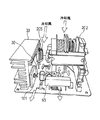
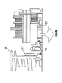
図2は本実施の形態の高周波加熱装置におけるプリント基板の一部分の実装状態を示す図である。また、図3は図2を矢印Ya方向で且つ斜め上方から見た図であり、図3は図
2を矢印Ya方向から見た図である。
FIG. 2 is a diagram showing a mounting state of a part of the printed circuit board in the high-frequency heating device of the present embodiment. 3 is a view of FIG. 2 as viewed from the direction of the arrow Ya and obliquely from above, and FIG. 3 is a view of FIG. 2 as viewed from the direction of the arrow Ya.
図2に示すように、シャント抵抗30は、プリント基板32上において放熱板33に取り付けられたダイオードブリッジ101およびIGBT205(トランジスタ203と転流ダイオード204とで構成される)と略同一直線上に配置されている。この場合、冷却風は図3に示すように昇圧トランス202の実装側からセメント抵抗50の実装側に向けて流れるようになっている。
As shown in FIG. 2, the
なお、図3において、主要部品の配置レイアウトは、概略述べると、昇圧トランス202が放熱板33に対し離間して対向配置され、昇圧トランス202の風上側(紙面の奥側)には主に高電圧部品が、昇圧トランス202の風下側(紙面の手前側)には主に制御回路部品や弱電回路部品が、プリント基板32上に実装された形態となっている。
In FIG. 3, the layout of the main components is roughly described. The step-up
そして、冷却風の一部は放熱板33と昇圧トランス202との間の空間を流れるが、この空間の風路上に沿ってシャント抵抗30がプリント基板32上に実装されているので、冷却風が、シャント抵抗30によって遮られることなく殆どが通過して行く。すなわち、シャント抵抗30による冷却風の阻害要因が最小限に抑えられている。 なお、シャント抵抗30は風路上に沿って配置してもその形状によって冷却風の当たる面積が大きくなる可能性もあるので、このような場合には、冷却風が当たる面積が最小になる向きにシャント抵抗30を配置するようにすれば良い。
A part of the cooling air flows through the space between the
また、図4にも示すように、昇圧トランス202の下方に潜り込んで昇圧トランス202を通過する冷却風が、風下側のセメント抵抗50に至るが、セメント抵抗50が冷却風の風路に対し略交差する方向に実装されているので、当該冷却風はセメント抵抗50の側面全域に当たる。この結果、セメント抵抗50は効率良く冷却される。
Also, as shown in FIG. 4, the cooling air that has entered under the step-up
更に、冷却風には昇圧トランス202の上方を通過するものもあり、この冷却風はセメント抵抗50の側面上方から上面全域に当たる。したがって、セメント抵抗50を冷却風の風路に対し略交差する方向に配置することで、上面全域を均等、且つ、確実に冷却することが可能となる。
なお、セメント抵抗50は風路に対し略交差する方向に配置してもその形状によって冷却風の当たる面積が小さくなる可能性もあるので、このような場合には、冷却風が当たる面積が最大になる向きにセメント抵抗50を配置するようにすれば良い。
Furthermore, some cooling air passes above the step-up
Note that even if the
このように、本実施の形態に係る高周波加熱装置によれば、単方向電源部1の出力電流を測定するために用いるシャント抵抗30を、プリント基板32上を流れる冷却風の風路に沿ってプリント基板32上に配置したので、冷却風の流れを阻害する割合を最小限に抑えることができ、冷却効率の向上が図れる。
また、セメント抵抗50を冷却風の風路に対し略交差する方向に配置したので、発熱するセメント抵抗50を効率良く冷却することが可能となる。
そして、これらシャント抵抗30およびセメント抵抗50の配置構成によって、高周波加熱装置本体の小型化に伴う省スペース化を行っても効率の良い冷却が可能となる。
As described above, according to the high-frequency heating device according to the present embodiment, the
In addition, since the
The arrangement configuration of the
なお、シャント抵抗30を、プリント基板32上を流れる冷却風の風路に沿って配置することは、セメント抵抗50をシャント抵抗30の風下側に配置しなければならないような場合に、セメント抵抗50を冷却する点も含めて冷却効率の面で効果的である。
また、セメント抵抗50以外にも通電することにより発熱する部品があれば、同様に配置すると良い。
Note that the arrangement of the
In addition to the
なお、上記した実施の形態では、セメント抵抗50は、図1に示したように、単方向電源部1の直流出力端と制御部7の電源端子部との間に介挿するとしたが、この構成に代わって、商用電源20両端にそれぞれダイオード207,209を介挿して交流電源を整流後、それぞれのダイオード207,209の接続点と制御部7の電源端子部との間にセメント抵抗50を介挿しても同様な効果が得られることは言うまでもない。
In the above-described embodiment, the
以上述べたように、本発明に係る高周波加熱装置によれば、単方向電源部の出力電流を測定するために用いるシャント抵抗は、プリント基板上を流れる冷却風の風路に沿って該プリント基板上に配置されるので、冷却風の流れを阻害する割合を最小限にして、冷却効率の向上が図れる。 As described above, according to the high-frequency heating device according to the present invention, the shunt resistor used for measuring the output current of the unidirectional power supply section is the printed circuit board along the air path of the cooling air flowing on the printed circuit board. Since it arrange | positions above, the ratio which inhibits the flow of cooling air can be made into the minimum, and the improvement of cooling efficiency can be aimed at.
また、発熱を伴うセメント抵抗は、冷却風の風路に対し略交差する方向に配置されるので、効率良く冷却される。 Moreover, since the cement resistance accompanied by heat generation is disposed in a direction substantially intersecting the cooling air flow path, it is efficiently cooled.
従って、高周波加熱装置本体の小型化に伴う省スペース化によって、プリント基板上に配置する電気部品の実装密度が高められても、発熱部品を効率良く冷却することができる。言い換えれば、省スペース化を可能にし高周波加熱装置本体の小型化を実現できる。 Therefore, even if the mounting density of the electrical components arranged on the printed circuit board is increased due to the space saving accompanying the downsizing of the high-frequency heating device main body, the heat generating components can be efficiently cooled. In other words, space can be saved and the high-frequency heating apparatus main body can be downsized.
1 単方向電源部
2 インバータ部
3 高圧整流回路
4 マグネトロン
7 制御部
30 シャント抵抗
31 バッファ
32 プリント基板
33 放熱板
50 セメント抵抗
101 ブリッジダイオード
205 IGBT
DESCRIPTION OF SYMBOLS 1 Unidirectional power supply part 2 Inverter part 3 High voltage rectifier circuit 4 Magnetron 7
Claims (2)
少なくとも1個の半導体スイッチング素子を有し、この半導体スイッチング素子をオン/オフすることにより前記単方向電源部からの電力を高周波電力に変換するインバータ部と、
前記インバータ部の出力電圧を昇圧する昇圧トランスと、
前記昇圧トランスの出力電圧を倍電圧整流する高圧整流部と、を有する高周波加熱装置において、
前記単方向電源部の出力電流を測定できる箇所に対して直列に介挿されるシャント抵抗を有し、
前記シャント抵抗は、前記基板上を流れる冷却風の風路に沿って該基板上に配置されるとともに前記ダイオードブリッジ及び前記スイッチング素子と略同一直線状に配置されることを特徴とする高周波加熱装置。 At least on the substrate, a unidirectional power supply unit that converts commercial power into a unidirectional using a diode bridge, and
An inverter unit having at least one semiconductor switching element, and converting the power from the unidirectional power source unit to high-frequency power by turning on / off the semiconductor switching element;
A step-up transformer for stepping up the output voltage of the inverter unit;
In a high-frequency heating device having a high-voltage rectifier that doubles the output voltage of the step-up transformer,
A shunt resistor interposed in series with respect to the location where the output current of the unidirectional power supply unit can be measured;
The high frequency heating apparatus, wherein the shunt resistor is disposed on the substrate along an air path of cooling air flowing on the substrate and is disposed substantially in the same straight line as the diode bridge and the switching element. .
Priority Applications (1)
| Application Number | Priority Date | Filing Date | Title |
|---|---|---|---|
| JP2007117412A JP4109311B2 (en) | 2007-04-26 | 2007-04-26 | High frequency heating device |
Applications Claiming Priority (1)
| Application Number | Priority Date | Filing Date | Title |
|---|---|---|---|
| JP2007117412A JP4109311B2 (en) | 2007-04-26 | 2007-04-26 | High frequency heating device |
Related Parent Applications (1)
| Application Number | Title | Priority Date | Filing Date |
|---|---|---|---|
| JP2003270458A Division JP4015597B2 (en) | 2003-04-11 | 2003-07-02 | High frequency heating device |
Publications (2)
| Publication Number | Publication Date |
|---|---|
| JP2007192545A true JP2007192545A (en) | 2007-08-02 |
| JP4109311B2 JP4109311B2 (en) | 2008-07-02 |
Family
ID=38448378
Family Applications (1)
| Application Number | Title | Priority Date | Filing Date |
|---|---|---|---|
| JP2007117412A Expired - Fee Related JP4109311B2 (en) | 2007-04-26 | 2007-04-26 | High frequency heating device |
Country Status (1)
| Country | Link |
|---|---|
| JP (1) | JP4109311B2 (en) |
Cited By (2)
| Publication number | Priority date | Publication date | Assignee | Title |
|---|---|---|---|---|
| CN108323135A (en) * | 2018-04-26 | 2018-07-24 | 广东美的厨房电器制造有限公司 | Power supply unit and microwave cooking appliances |
| CN108347869A (en) * | 2018-04-26 | 2018-07-31 | 广东美的厨房电器制造有限公司 | Radiator, for electric installation and microwave cooking electric appliance |
-
2007
- 2007-04-26 JP JP2007117412A patent/JP4109311B2/en not_active Expired - Fee Related
Cited By (4)
| Publication number | Priority date | Publication date | Assignee | Title |
|---|---|---|---|---|
| CN108323135A (en) * | 2018-04-26 | 2018-07-24 | 广东美的厨房电器制造有限公司 | Power supply unit and microwave cooking appliances |
| CN108347869A (en) * | 2018-04-26 | 2018-07-31 | 广东美的厨房电器制造有限公司 | Radiator, for electric installation and microwave cooking electric appliance |
| CN108347869B (en) * | 2018-04-26 | 2024-06-07 | 广东美的厨房电器制造有限公司 | Radiator, power supply device and microwave cooking appliance |
| CN108323135B (en) * | 2018-04-26 | 2024-08-09 | 广东美的厨房电器制造有限公司 | Power supply and microwave cooking appliances |
Also Published As
| Publication number | Publication date |
|---|---|
| JP4109311B2 (en) | 2008-07-02 |
Similar Documents
| Publication | Publication Date | Title |
|---|---|---|
| JP3986462B2 (en) | High frequency heating device | |
| JP4109311B2 (en) | High frequency heating device | |
| JP4015597B2 (en) | High frequency heating device | |
| KR100989329B1 (en) | High frequency heater | |
| JP4001564B2 (en) | Printed circuit board with thermistor | |
| JP5003752B2 (en) | Power supply | |
| JP2013252006A (en) | Motor driving device and air conditioner including the same | |
| JP4001078B2 (en) | High frequency heating device | |
| JP4243299B2 (en) | High frequency heating device | |
| KR100762300B1 (en) | Air-cooled high-voltage transformer | |
| JP5621252B2 (en) | Inverter device | |
| JP4765441B2 (en) | Induction heating device | |
| JP2005216602A (en) | Magnetron drive power supply | |
| JP2011060567A (en) | Power source for driving magnetron | |
| KR20180124680A (en) | Heat shielding structure applied to welder | |
| CN108323135B (en) | Power supply and microwave cooking appliances | |
| KR102292255B1 (en) | Induction heat cooking apparatus and the driving module thereof | |
| JP6832810B2 (en) | Power converter | |
| WO2023248413A1 (en) | Motor drive device and air conditioner | |
| JP2003116274A (en) | Power supply | |
| JP5011930B2 (en) | Induction heating rice cooker | |
| JP2004282946A (en) | DC / DC converter | |
| JPH09294372A (en) | Switching power supply | |
| JP2006324027A (en) | Magnetron drive power supply | |
| JP2007280628A (en) | High frequency heating device |
Legal Events
| Date | Code | Title | Description |
|---|---|---|---|
| A621 | Written request for application examination |
Free format text: JAPANESE INTERMEDIATE CODE: A621 Effective date: 20070427 |
|
| A131 | Notification of reasons for refusal |
Free format text: JAPANESE INTERMEDIATE CODE: A131 Effective date: 20070815 |
|
| A521 | Request for written amendment filed |
Free format text: JAPANESE INTERMEDIATE CODE: A523 Effective date: 20071012 |
|
| RD02 | Notification of acceptance of power of attorney |
Free format text: JAPANESE INTERMEDIATE CODE: A7422 Effective date: 20071113 |
|
| RD04 | Notification of resignation of power of attorney |
Free format text: JAPANESE INTERMEDIATE CODE: A7424 Effective date: 20071120 |
|
| TRDD | Decision of grant or rejection written | ||
| A01 | Written decision to grant a patent or to grant a registration (utility model) |
Free format text: JAPANESE INTERMEDIATE CODE: A01 Effective date: 20080305 |
|
| A61 | First payment of annual fees (during grant procedure) |
Free format text: JAPANESE INTERMEDIATE CODE: A61 Effective date: 20080403 |
|
| FPAY | Renewal fee payment (event date is renewal date of database) |
Free format text: PAYMENT UNTIL: 20110411 Year of fee payment: 3 |
|
| R150 | Certificate of patent or registration of utility model |
Free format text: JAPANESE INTERMEDIATE CODE: R150 Ref document number: 4109311 Country of ref document: JP Free format text: JAPANESE INTERMEDIATE CODE: R150 |
|
| FPAY | Renewal fee payment (event date is renewal date of database) |
Free format text: PAYMENT UNTIL: 20120411 Year of fee payment: 4 |
|
| FPAY | Renewal fee payment (event date is renewal date of database) |
Free format text: PAYMENT UNTIL: 20130411 Year of fee payment: 5 |
|
| FPAY | Renewal fee payment (event date is renewal date of database) |
Free format text: PAYMENT UNTIL: 20130411 Year of fee payment: 5 |
|
| FPAY | Renewal fee payment (event date is renewal date of database) |
Free format text: PAYMENT UNTIL: 20140411 Year of fee payment: 6 |
|
| LAPS | Cancellation because of no payment of annual fees |