JP2007192553A - Tilt sensor and tilt angle measuring method - Google Patents
Tilt sensor and tilt angle measuring method Download PDFInfo
- Publication number
- JP2007192553A JP2007192553A JP2006008259A JP2006008259A JP2007192553A JP 2007192553 A JP2007192553 A JP 2007192553A JP 2006008259 A JP2006008259 A JP 2006008259A JP 2006008259 A JP2006008259 A JP 2006008259A JP 2007192553 A JP2007192553 A JP 2007192553A
- Authority
- JP
- Japan
- Prior art keywords
- tuning fork
- fork vibrator
- double tuning
- fixed
- tilt
- Prior art date
- Legal status (The legal status is an assumption and is not a legal conclusion. Google has not performed a legal analysis and makes no representation as to the accuracy of the status listed.)
- Granted
Links
- 238000000034 method Methods 0.000 title description 12
- 238000007789 sealing Methods 0.000 claims abstract description 12
- 238000001514 detection method Methods 0.000 abstract description 7
- 238000000691 measurement method Methods 0.000 abstract description 3
- 238000005259 measurement Methods 0.000 description 11
- 230000005284 excitation Effects 0.000 description 8
- 239000000463 material Substances 0.000 description 7
- 239000013078 crystal Substances 0.000 description 6
- 230000006835 compression Effects 0.000 description 5
- 238000007906 compression Methods 0.000 description 5
- 238000010586 diagram Methods 0.000 description 4
- 230000005484 gravity Effects 0.000 description 4
- 230000015572 biosynthetic process Effects 0.000 description 2
- 229910052451 lead zirconate titanate Inorganic materials 0.000 description 2
- 239000010453 quartz Substances 0.000 description 2
- 230000035945 sensitivity Effects 0.000 description 2
- VYPSYNLAJGMNEJ-UHFFFAOYSA-N silicon dioxide Inorganic materials O=[Si]=O VYPSYNLAJGMNEJ-UHFFFAOYSA-N 0.000 description 2
- 229910001220 stainless steel Inorganic materials 0.000 description 2
- 239000010935 stainless steel Substances 0.000 description 2
- WSMQKESQZFQMFW-UHFFFAOYSA-N 5-methyl-pyrazole-3-carboxylic acid Chemical compound CC1=CC(C(O)=O)=NN1 WSMQKESQZFQMFW-UHFFFAOYSA-N 0.000 description 1
- 229910000906 Bronze Inorganic materials 0.000 description 1
- 229910013641 LiNbO 3 Inorganic materials 0.000 description 1
- OAICVXFJPJFONN-UHFFFAOYSA-N Phosphorus Chemical compound [P] OAICVXFJPJFONN-UHFFFAOYSA-N 0.000 description 1
- XLOMVQKBTHCTTD-UHFFFAOYSA-N Zinc monoxide Chemical compound [Zn]=O XLOMVQKBTHCTTD-UHFFFAOYSA-N 0.000 description 1
- 239000000853 adhesive Substances 0.000 description 1
- 230000001070 adhesive effect Effects 0.000 description 1
- 229910052782 aluminium Inorganic materials 0.000 description 1
- XAGFODPZIPBFFR-UHFFFAOYSA-N aluminium Chemical compound [Al] XAGFODPZIPBFFR-UHFFFAOYSA-N 0.000 description 1
- 230000002238 attenuated effect Effects 0.000 description 1
- 230000005540 biological transmission Effects 0.000 description 1
- 239000010974 bronze Substances 0.000 description 1
- 239000000470 constituent Substances 0.000 description 1
- KUNSUQLRTQLHQQ-UHFFFAOYSA-N copper tin Chemical compound [Cu].[Sn] KUNSUQLRTQLHQQ-UHFFFAOYSA-N 0.000 description 1
- 230000007423 decrease Effects 0.000 description 1
- 230000000694 effects Effects 0.000 description 1
- HFGPZNIAWCZYJU-UHFFFAOYSA-N lead zirconate titanate Chemical compound [O-2].[O-2].[O-2].[O-2].[O-2].[Ti+4].[Zr+4].[Pb+2] HFGPZNIAWCZYJU-UHFFFAOYSA-N 0.000 description 1
- GQYHUHYESMUTHG-UHFFFAOYSA-N lithium niobate Chemical compound [Li+].[O-][Nb](=O)=O GQYHUHYESMUTHG-UHFFFAOYSA-N 0.000 description 1
- 229910052751 metal Inorganic materials 0.000 description 1
- 239000002184 metal Substances 0.000 description 1
- 230000003287 optical effect Effects 0.000 description 1
- 239000011347 resin Substances 0.000 description 1
- 229920005989 resin Polymers 0.000 description 1
- 239000004065 semiconductor Substances 0.000 description 1
Images






Landscapes
- Gyroscopes (AREA)
- Piezo-Electric Or Mechanical Vibrators, Or Delay Or Filter Circuits (AREA)
Abstract
【課題】電気的に検出する分解能を高め、精度の高い傾き角度の測定が可能な水準器としての傾斜センサおよび傾き角度の測定方法を提供する。
【解決手段】傾斜センサ10は、傾きを所定の方向の力に変換するカンチレバー部30と、カンチレバー部30に接続され、力を受けて共振周波数が変化する双音叉振動子20と、カンチレバー部30に接続された錘部27と、双音叉振動子20の共振周波数の変化に基づいて傾き角度を算出する回路を含む制御回路部29とが基台としての収納容器11の凹部12に収納されている。収納容器11の凹部12の開口部は、封止部としての蓋体31によって気密に封止されている。
【選択図】図1
A tilt sensor as a level and a tilt angle measurement method capable of measuring a tilt angle with high accuracy by increasing the resolution for electrical detection.
A tilt sensor 10 includes a cantilever portion 30 that converts a tilt into a force in a predetermined direction, a double tuning fork vibrator 20 that is connected to the cantilever portion 30 and changes a resonance frequency upon receiving the force, and a cantilever portion 30. And a control circuit unit 29 including a circuit for calculating an inclination angle based on a change in the resonance frequency of the double tuning fork vibrator 20 are accommodated in the recess 12 of the storage container 11 serving as a base. Yes. The opening part of the recessed part 12 of the storage container 11 is airtightly sealed with the cover body 31 as a sealing part.
[Selection] Figure 1
Description
本発明は、構造体の被測定面に載置し、その被測定面の傾きの大きさを電気的に測定する傾斜センサおよび傾き角度の測定方法に関する。 The present invention relates to a tilt sensor that is placed on a surface to be measured of a structure and electrically measures the inclination of the surface to be measured, and a method for measuring a tilt angle.
建造物などの構造体の水平度或いは鉛直度を得るために、その構造体の被測定面である平面に載置して、その面の傾きを検出するものに水準器がある。近年、特許文献1に開示されるような電気的に傾きの大きさを測定する水準器(傾斜センサ)が提案されている。 In order to obtain the level or verticality of a structure such as a building, there is a level that is placed on a plane that is a surface to be measured of the structure and detects the inclination of the surface. In recent years, a level (tilt sensor) that electrically measures the magnitude of tilt as disclosed in Patent Document 1 has been proposed.
この特許文献1に示す水準器について図13を用いて説明する。なお、図13は、従来の水準器の概略の構成を示す正面図である。図13によれば、従来の水準器1000は、載置面1016を有した本体部1010に、小球体1011を内包し、円弧状に形成された管1012と、管1012の外壁に沿って配列された複数のセンサ1013からなるセンサアレイ1014とを有している。小球体1011は浮力を有しており、管1012が傾くことによって管1012内を自由に移動できるように設けられている。さらに、本体部1010には、測定信号を処理し傾きの大きさ(角度)を算出する電子回路部1015が設けられている。
The level shown in Patent Document 1 will be described with reference to FIG. FIG. 13 is a front view showing a schematic configuration of a conventional level. Referring to FIG. 13, a
水準器1000の傾斜の大きさの検出方法について説明する。先ず、複数のセンサ1013を順次切換ながら走査して、管1012内へパルス信号を送信し、管1012内の小球体1011からの反射信号或いは透過信号の有無によって小球体1011と対向するセンサ1013aを検出する。この検出されたセンサ1013aの位置に基づいて電子回路部1015が傾きの大きさを算出する。
A method for detecting the inclination of the
しかしながら、従来の水準器1000は、複数のセンサ1013それぞれが、所定の長さを有しているため、小球体1011の位置が変わっても、それぞれのセンサ1013の長さ方向の間にあれば、検出されるセンサ1013は変わらない。換言すれば、小球体1011の位置が、順次配列されたそれぞれのセンサ1013の境を越えるまで移動しないと隣りのセンサ1013が検出されない。即ち、従来の水準器1000は、検出波形が階段状となることから検出の分解能が低くなり、さらに精度の高い傾き角度を測定することが困難であるという課題を有していた。
However, in the
本発明は、上述の課題を解決するためになされたもので、電気的に検出する分解能を高め、精度の高い傾き角度の測定が可能な水準器としての傾斜センサおよび傾き角度の測定方法を提供することを目的とする。 The present invention has been made to solve the above-described problems, and provides a tilt sensor as a level and a tilt angle measuring method capable of measuring a tilt angle with high accuracy by increasing the resolution of electrical detection. The purpose is to do.
本発明の傾斜センサは、基台に固定された固定部と、前記固定部と接続された可撓性を有する支持部と、前記支持部を介して前記固定部と接続され、前記支持部の可撓性によって移動可能な揺動部と、一対の振動腕と前記振動腕の両端にそれぞれ延設された基部とを有し、前記揺動部の移動方向に交差する方向が前記振動腕の振動方向となるように、前記基部の一方が前記固定部に固着され、前記基部の他方が前記揺動部に固着された双音叉振動子と、前記双音叉振動子を発振させる駆動回路部と前記双音叉振動子の共振周波数の変化に基づき傾き角度を算出する演算回路部とを含む制御回路部と、を有していることを特徴とする。 The tilt sensor according to the present invention is connected to the fixing portion via the supporting portion, the fixing portion fixed to the base, the flexible supporting portion connected to the fixing portion, and the supporting portion. A swinging portion movable by flexibility; a pair of vibrating arms; and a base portion extending at each end of the vibrating arm, the direction intersecting the moving direction of the swinging portion being A double tuning fork vibrator in which one of the bases is fixed to the fixed part and the other of the bases is fixed to the swinging part so as to be in a vibration direction; and a drive circuit unit that oscillates the double tuning fork vibrator; And a control circuit unit including an arithmetic circuit unit that calculates an inclination angle based on a change in the resonance frequency of the double tuning fork vibrator.
本発明の傾斜センサによれば、傾き角度の測定分解能を高くすることが可能となり、精度の高い傾き角度を測定できる傾斜センサを提供することが可能となる。本発明の傾斜センサは、基台に固定された固定部と可撓性を有する支持部を介して接続された揺動部を有している。揺動部は、支持部の有している可撓性により移動することが可能であり、基台を傾けることにより、支持部近傍を支点として重力と釣合うように回転方向に移動しようとする力(以下、「力」と呼ぶ。)を生じる。双音叉振動子は、この力を振動腕の振動方向と交差する方向に受けるように固定部と揺動部とにそれぞれの基部が固着されており、受けた力の大きさにより共振周波数が所定量変化する。この力は、基台の傾き角度に伴って変化するため、制御回路部によって双音叉振動子の共振周波数の変化量を測定し、この測定された共振周波数の変化量に基づいて傾き角度を算出することが可能となる。双音叉振動子の共振周波数の変化は、傾き角度の変化に伴って連続的に変化するため、傾き角度の測定分解能が高まり精度の高い傾き角度を測定できる傾斜センサを提供することが可能となる。 According to the tilt sensor of the present invention, the tilt angle measurement resolution can be increased, and a tilt sensor capable of measuring a tilt angle with high accuracy can be provided. The tilt sensor of the present invention has a fixed portion fixed to a base and a swinging portion connected via a flexible support portion. The swinging part can move due to the flexibility of the support part, and by tilting the base, the swinging part tends to move in the rotational direction so as to balance gravity with the vicinity of the support part as a fulcrum. Force (hereinafter referred to as “force”) is generated. In the double tuning fork vibrator, the base part is fixed to the fixed part and the swinging part so as to receive this force in a direction crossing the vibration direction of the vibrating arm, and the resonance frequency depends on the magnitude of the received force. Quantitative change. Since this force changes with the tilt angle of the base, the control circuit section measures the amount of change in the resonant frequency of the double tuning fork vibrator, and calculates the tilt angle based on the measured amount of change in the resonant frequency. It becomes possible to do. Since the change in the resonance frequency of the double tuning fork vibrator changes continuously with the change in the tilt angle, it becomes possible to provide a tilt sensor capable of measuring the tilt angle with high accuracy by increasing the tilt angle measurement resolution. .
また、前記固定部と、前記支持部と、前記揺動部とは一体的に形成されていることが望ましい。 Moreover, it is desirable that the fixed portion, the support portion, and the swing portion are integrally formed.
このようにすれば、一つの材料から一体的に形成されることにより、それぞれの接続が不要となり簡易な形成が可能となる。 In this way, by forming integrally from one material, each connection becomes unnecessary and simple formation becomes possible.
また、前記揺動部には、前記双音叉振動子の接続側と前記支持部を挟む反対側の部分に錘部が形成されていることが望ましい。 Further, it is preferable that a weight portion is formed on the swinging portion on the opposite side of the connecting side of the double tuning fork vibrator and the support portion.
このようにすれば、揺動部の自重に錘部の重量が加えられるため、揺動部の重量が重くなり、傾きを与えられることにより生じる力が大きくなる。これによって、双音叉振動子の共振周波数の変化量が大きくなり、傾き角度の検出の感度を高めることが可能となる。 In this way, since the weight of the weight is added to the weight of the swinging part, the weight of the swinging part is increased, and the force generated by giving an inclination increases. As a result, the amount of change in the resonance frequency of the double tuning fork vibrator is increased, and the sensitivity of detecting the tilt angle can be increased.
前記支持部、前記揺動部および前記錘部は、中空に保持されていることが望ましい。 It is desirable that the support portion, the swinging portion, and the weight portion are held hollow.
このようにすれば、傾きを与えられた揺動部および錘部が自由に移動することができることから、生じる力を減衰させることなくそのまま双音叉振動子に伝えることが可能となる。即ち、傾き角度の測定精度を高めることが可能となる。 In this way, since the tilted swinging part and the weight part can freely move, the generated force can be transmitted to the double tuning fork vibrator as it is without being attenuated. That is, it is possible to increase the measurement accuracy of the tilt angle.
また、前記基台は、少なくとも一面に開口部を有する凹部が形成された収納容器であり、前記収納容器の内には、前記固定部と、前記支持部と、前記揺動部と、前記双音叉振動子と、前記制御回路部とが収納されており、前記開口部は、封止部によって閉口されていることが望ましい。 The base is a storage container in which a recess having an opening on at least one surface is formed. Inside the storage container, the fixing part, the support part, the swing part, and the double part are provided. It is desirable that a tuning fork vibrator and the control circuit unit are accommodated, and the opening is closed by a sealing unit.
このようにすれば、傾き角度の測定部分と制御回路とが同じ収納容器に収納されていることから、傾き角度の測定と演算処理を一括で行うことが可能な傾斜センサを提供することができる。 In this way, since the tilt angle measurement part and the control circuit are housed in the same storage container, it is possible to provide a tilt sensor capable of collectively performing the tilt angle measurement and the arithmetic processing. .
また、前記収納容器は、表裏面にそれぞれ開口部を有する表側凹部と裏側凹部とが形成されており、前記表側凹部には、前記固定部と、前記支持部と、前記揺動部と、前記双音叉振動子とが収納され、前記裏側凹部には、前記制御回路部が収納されており、前記それぞれの開口部は、封止部によって閉口されていることが望ましい。 Further, the storage container is formed with a front-side recess and a back-side recess each having an opening on the front and back surfaces, and the front-side recess includes the fixing portion, the support portion, the swinging portion, It is preferable that a double tuning fork vibrator is accommodated, the control circuit portion is accommodated in the back-side recess, and each opening is closed by a sealing portion.
このようにすれば、表側凹部と裏側凹部とを、それぞれ別々に加工を行うことが可能となり、より精度を高めた調整を行うことが可能となる。 If it does in this way, it will be possible to process a front side crevice and a back side crevice separately, respectively, and it will become possible to perform adjustment which raised more accuracy.
前記双音叉振動子が収納される前記凹部は、前記封止部によって低圧状態で閉口されていることが望ましい。 It is preferable that the concave portion in which the double tuning fork vibrator is accommodated is closed in a low pressure state by the sealing portion.
このようにすれば、双音叉振動子の振動を阻害する空気抵抗を抑えることができ、双音叉振動子の、より安定した振動特性を得ることが可能となる。 In this way, it is possible to suppress the air resistance that inhibits the vibration of the double tuning fork vibrator, and to obtain more stable vibration characteristics of the double tuning fork vibrator.
本発明の、傾き角度の測定方法は、基台に固着された固定部に接続され、可撓性を有する支持部を介し設けられた揺動部に生じる、前記基台が傾くことによって前記揺動部が移動しようとする力を、前記揺動部の移動方向に交差する方向が振動腕の振動方向となるように、前記振動腕の両端に形成された基部が前記固定部と前記揺動部とに固着された双音叉振動子に伝え、伝えられた前記力の大きさによって変化する前記双音叉振動子の共振周波数の変化を測定し、前記測定された共振周波数の変化に基づいて傾きの大きさを算出することを特徴とする。 The tilt angle measuring method according to the present invention is connected to a fixed portion fixed to a base, and is generated by a swinging portion provided via a flexible support portion. The bases formed at both ends of the vibrating arm are configured so that the direction in which the moving part moves is intersected with the moving direction of the swinging arm is the vibrating direction of the vibrating arm. Measure the change in the resonance frequency of the double tuning fork vibrator, which changes depending on the magnitude of the transmitted force, and tilt based on the change in the measured resonance frequency. It is characterized by calculating the size of.
本発明の傾き角度の測定方法によれば、傾き角度の測定分解能を高くすることが可能となり、精度の高い傾き角度を測定できる傾斜の測定方法を提供することが可能となる。本発明の傾き角度の測定方法は、基台の傾きにより、この基台に固定された固定部と可撓性を有する支持部を介して接続された揺動部が移動しようとする力が伝えられた双音叉振動子の共振周波数の変化に基づいて算出される。この力は、基台の傾き角度に伴って連続的に変化し、双音叉振動子の共振周波数もこの力の大きさによって変化するため傾き角度の測定分解能が高まり精度の高い傾き角度を測定することが可能となる。 According to the tilt angle measuring method of the present invention, the tilt angle measurement resolution can be increased, and a tilt measuring method capable of measuring a tilt angle with high accuracy can be provided. The tilt angle measuring method according to the present invention transmits a force that the fixed part fixed to the base and the swinging part connected via the flexible support part move due to the tilt of the base. It is calculated based on the change in the resonance frequency of the obtained double tuning fork vibrator. This force changes continuously with the tilt angle of the base, and the resonance frequency of the double tuning fork vibrator also changes according to the magnitude of this force, so the tilt angle measurement resolution increases and the tilt angle is measured with high accuracy. It becomes possible.
本発明に係る傾斜センサの最良の形態について、以下に図面を用いて説明する。
(第一実施形態)
The best mode of the tilt sensor according to the present invention will be described below with reference to the drawings.
(First embodiment)
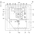
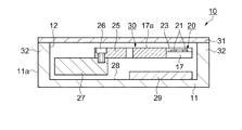
先ず、図1、図2および図3を参照して第一実施形態の傾斜センサの構成について説明する。図1は、第一実施形態の傾斜センサの概略を示す平面図である。図2は、図1のA−A断面を示す正面図である。図3は、図1のB−B断面を示す右側面図である。 First, the configuration of the tilt sensor according to the first embodiment will be described with reference to FIGS. 1, 2, and 3. FIG. 1 is a plan view schematically showing the tilt sensor of the first embodiment. FIG. 2 is a front view showing a cross section AA of FIG. FIG. 3 is a right side view showing the BB cross section of FIG. 1.
図1、図2および図3に示すように、傾斜センサ10は、傾きを所定の方向の力に変換するカンチレバー部30と、カンチレバー部30に接続された双音叉振動子20および錘部27と、制御回路部29とが基台としての収納容器11の凹部12に収納されている。収納容器11の凹部12の開口部は、封止部としての蓋体31によって気密に封止されている。
As shown in FIGS. 1, 2, and 3, the
次に、上述の傾斜センサ10を構成部位の詳細を順次説明する。先ず、双音叉振動子20の概略について説明するが、構成、動作等についての詳細につては後段で説明する。
双音叉振動子20は、例えば、厚み方向を結晶軸のZ軸(光軸)とした、いわゆるZ板水晶を用い、Y軸方向(機械軸)に伸びる2つ(一対)の振動腕21と、振動腕21の両端をそれぞれ支持する基部22a,22bとにより形成されている。なお、振動腕21は、X軸(電気軸)方向に振動する。
Next, details of the constituent parts of the
The double
次に、カンチレバー部30について説明する。カンチレバー部30は、固定部14と支持部19と揺動部17とから構成されている。カンチレバー部30は、例えば、リン青銅、バネ性ステンレスなどの可撓性を有する材料を切削加工などによって一体的に形成されている。なお、固定部14と支持部19と揺動部17とは、それぞれ個別に形成し、接続することも可能であるが、本第一実施形態のように一つの材料から一体的に形成すれば、それぞれの接続が不要となり簡易に形成することに好適である。
Next, the
固定部14は、収納容器11の凹部12の底面13に固定ボルト15などによって固定されている。このとき固定部14は、収納容器11を被測定物上に載置する載置面11aの垂線上に、カンチレバー部30の支持部19および錘部27の接続位置が在るように固定される。固定部14の一方には、固定部14の表面14aと段差状の底面24が形成されており、この底面24に双音叉振動子20の一方の基部22bが固着されている。さらに、固定部14には、双音叉振動子20の振動腕21の延伸方向と略同じ方向に延出する突出部16が形成されている。この突出部16の一方端には、突出部16の延出方向と交差する方向に延出された支持部19が形成されている。
The fixing
支持部19は、例えば、幅寸法が0.2mm程度の薄肉形状(板バネ形状)をなしている。支持部19は、この薄肉形状(板バネ形状)により突出部16との交点近傍を支点として撓むことができる、いわゆる可撓性(バネ性)を有している。支持部19の一端は、揺動部17から固定部14に向かい突出するように形成された突出部18と接続されている。支持部19と突出部18とは、突出部18の突出方向と支持部19の延在方向とが交差する方向に接続されている。
The
揺動部17の一方には、突出部16と接触しないように突出部16を回り込んだ錘固定部25が形成されており、この錘固定部25に錘部27が固定ボルト26などにより固定されている。この揺動部17、突出部18および錘部27は、可撓性を有する支持部19が撓むことによって自由に移動することが可能である。なお、支持部19、揺動部17、突出部18および錘部27は、他の構成部位との接触による移動抵抗を防ぐため中空に保持されている。さらに、揺動部17の他方には、揺動部17の表面17aと段差状の底面23が形成されており、この底面23に双音叉振動子20の一方の基部22aが固着されている。前述した揺動部17の他方とは、錘部27と支持部19を挟み反対側の端部付近であって固定部14に形成された段差状の底面24と対向する部分を示している。
A
双音叉振動子20は、振動腕21が中空に保持されるように、それぞれの基部22b,22aが固定部14の底面24と揺動部17の底面23に固着される。これにより固定部14と揺動部17とが双音叉振動子20によって橋渡し状に接続される。
In the double
前述のカンチレバー部30が固定される収納容器11は、例えば、ステンレス、アルミニウムなどの金属板の表面に開口部を有する凹部12が形成されている。凹部12は、2つの底面13,28が設けられた多段形状であり、底面28の方が底面13よりも深く形成されている。これは、底面13に固定部14が固定されたカンチレバー部30のうち、揺動部17、錘部27、双音叉振動子20を中空に保持するためである。さらに、底面28には、揺動部17、錘部27および双音叉振動子20と接触しないように制御回路部29が接続されている。
The
収納容器11の外枠部32の上面33には、収納容器11の凹部12の開口部を覆うように蓋体31が気密的に接合されている。このとき、凹部12の中は、例えば、1×10⁻¹Pa(パスカル)以下の真空度を有した低圧状態とされている。これは、双音叉振動子20の振動効率を高める(振動特性を向上させる)ためである。
A
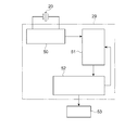
次に、制御回路部29について説明する。制御回路部29の構成を、図4のブロック図に示す。図4に示すように、双音叉振動子20と接続された駆動回路部50と、駆動回路部50から出力される双音叉振動子20の共振周波数の変化を検知する検知回路部51と、検知回路部51との情報に基づいて傾斜の角度を算出する演算回路部52とを有している。制御回路部29は、例えば、半導体回路チップ或いは種々の回路素子を搭載した回路基板等で構成されており、収納容器11の凹部12の底面28に固着されている。
なお、演算回路部52から出力される情報を表示する表示部53と接続することも可能である。この場合、表示部53は、図示しないが収納容器11或いは蓋体31に設けてもよく、さらには、傾斜センサ10と別体として設けてもよい。
Next, the
It is also possible to connect to a
次に、図5および図6を用い、双音叉振動子20の詳細な構成および動作について説明する。図5は、双音叉振動子の電極形状を示す概略図である。図6は、双音叉振動子の振動形態を示す模式図である。
Next, a detailed configuration and operation of the double
双音叉振動子20は、例えば、水晶などの圧電基材から形成される。本第一実施形態の双音叉振動子20は、0.1mm程度の厚さの水晶基材を用いた双音叉型の水晶振動子である。双音叉振動子20は、水晶の結晶軸のX軸回りに所定の角度回転させたZ´軸方向を厚さ方向とし、X軸方向に並んだ2つの振動腕21が、Y軸方向に伸びており、振動腕21の両端が基部22a,22bと接続されている。
The double
振動腕21の表面には、振動腕21を励振させるための電極形状の一例としての、励振電極46,47が形成されている。励振電極46,47は、それぞれの振動腕21の中央部に設けられた電極40,41と、振動腕21の基部22a,22bとの接続部に近い部分(電極40,41の両側の部分)に設けられた電極42,43,44,45とから構成されている。なお、図示しないが、振動腕の裏面にも同様な構成の励振電極が形成されている。また、側面にも励振電極が設けられていることもある。
図6を参照しながら振動について説明する。先ず、図6(b)に示すように、一方の励振電極46を構成する電極40にマイナス(−)電位、電極42と電極43にプラス(+)電位を印加する。同時に他方の励振電極47を構成する電極41にプラス(+)電位、電極44と電極45にマイナス(−)電位を印加する。このような電位を印加することにより、図6(a)で示すように略平行状態であったそれぞれの振動腕21が、図6(b)で示すように外側に撓む。
The vibration will be described with reference to FIG. First, as shown in FIG. 6B, a negative (−) potential is applied to the
続いて、図6(c)に示すように、それぞれの電極に図6(b)の電位とは逆の電位を印加する。即ち、一方の励振電極46を構成する電極40にプラス(+)電位、電極42と電極43にマイナス(−)電位を印加する。同時に他方の励振電極47を構成する電極41にマイナス(−)電位、電極44と電極45にプラス(+)電位を印加する。このような電位を印加することにより、それぞれの振動腕21は、図6(c)で示すように内側に撓む。
Subsequently, as shown in FIG. 6C, a potential opposite to the potential of FIG. 6B is applied to each electrode. That is, a positive (+) potential is applied to the
上述の図6(b)と図6(c)の状態の電位を繰り返し印加することにより、所定の共振周波数で振動腕21が振動することになる。本第一実施形態では、共振周波数が約40KHzとなるように形成された双音叉振動子20を用いている。
By repeatedly applying the potentials shown in FIGS. 6B and 6C, the vibrating
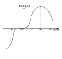
前述のように所定の共振周波数で振動する双音叉振動子20に、振動腕21の振動方向に交差する方向に圧縮の力が加えられたり、逆に引っ張りの力が加えられたりするとその共振周波数が変化する。本第一実施形態に示す傾斜センサ10は、この双音叉振動子20の特性を用いたものであり、この測定方法について図7および図8を用いて説明する。図7は、測定方法の概略を示す動作説明図であり、(a)は、被測定部に傾きがない場合を示し、(b)は、被測定部が反時計回りの傾きを有する場合を示し、(c)は、被測定部が時計回りの傾きを有する場合を示す。図8は、力を加えた時の双音叉振動子の周波数の変化を示すグラフである。
As described above, when a compression force is applied to the double
図7に沿って傾き角度の測定方法について説明するが、同図においては、収納容器は省略している。図7(a)に示す、鉛直線55上に支持部19および錘部27の固定ボルト26がある場合、即ちカンチレバー部30に傾きがない場合は、揺動部17に移動の力は発生しないため、双音叉振動子20には力が加わらない。
The method for measuring the tilt angle will be described with reference to FIG. 7, but the storage container is omitted in the figure. When the fixing
図7(b)に示す、カンチレバー部30が反時計方向に角度θ1傾くと、錘部27が接続された揺動部17は重力によって、支持部19の固定部14との交点付近の支点Qを中心として矢印R1の方向に移動しようとする力が発生する。このとき、揺動部17は、双音叉振動子20によって固定部14と橋渡し状に接続されているため、揺動部17は実際には移動せず、この移動しようとする力は、矢印P1の方向の力、即ち圧縮の力として双音叉振動子20に加わる。換言すれば、矢印P1の方向に加わる圧縮の力は、双音叉振動子20の振動腕21の振動方向に交差する方向に加わることになる。
When the
また、図7(c)に示すように、カンチレバー部30が時計方向に角度θ2傾くと、錘部27が接続された揺動部17は重力によって、支持部19の固定部14との交点付近の支点Qを中心として矢印R2の方向に移動しようとする力が発生する。このとき、揺動部17は、双音叉振動子20によって固定部14と橋渡し状に接続されているため、揺動部17は実際には移動せず、この移動しようとする力は、矢印P2の方向の力、即ち引っ張りの力として双音叉振動子20に加わる。
Further, as shown in FIG. 7C, when the
双音叉振動子20は、振動腕21の振動方向に交差する方向に圧縮の力を加えると、その共振周波数が低下し、逆に引っ張りの力が加わると共振周波数が上昇する特性を有している。従って、カンチレバー部30に、図7(b)に示す方向に角度θ1を与えた場合は、双音叉振動子20の共振周波数は低下することになる。この共振周波数の変化は、双音叉振動子20に加えられる力の大きさにほぼ比例関係を持っており、共振周波数の10%程度の変化を生じる。前述の圧縮および引っ張りの力は、カンチレバー部30の傾きの大きさによって変動するため、傾きの大きさによって双音叉振動子20の共振周波数の変化量が変動する。従って、この共振周波数の変化量を検出することによってカンチレバー部30の傾きを測定することが可能となる。
The double
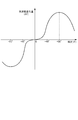
図8にカンチレバー部30の傾き角度と双音叉振動子20の共振周波数の変化の相関を測定した結果を示している。図8の縦軸は双音叉振動子20の共振周波数の変化量を示し、横軸はカンチレバー部30の傾きを示している。図8に示すように、カンチレバー部30の傾きが小さい範囲では共振周波数の変化が少なく、傾きが大きくなるに連れて共振周波数の変化量が大きくなり、傾きが90度で最大値を示す。
FIG. 8 shows the result of measuring the correlation between the tilt angle of the
上述の、第一実施形態の傾斜センサ10によれば、収納容器11の凹部12にカンチレバー部30の固定部14が固定されており、この固定部14と可撓性を有する支持部19を介して接続された揺動部17を有している。この収納容器11が傾いたとき、即ち、収納容器11の載置面11aが、傾きを持った被測定面に置かれたとき、揺動部17に支持部19近傍を支点Qとして重力と釣合うように回転方向に移動しようとする力を生じる。この力が、振動腕21の振動方向と交差する方向に受けるように固定部14と揺動部17とにそれぞれの基部22a,22bを固着された双音叉振動子20が受け、受けた力の大きさにより双音叉振動子20の共振周波数が所定量変化する。この力は、収納容器11の載置面11aの傾き角度に伴って変化するため、制御回路部29によって双音叉振動子20の共振周波数の変化量を測定し、この測定された共振周波数の変化量に基づいて傾き角度を算出することが可能となる。双音叉振動子20の共振周波数の変化は、傾き角度の変化に伴って連続的に変化するため、傾き角度の測定も連続的に行うことが可能となり、換言すれば測定分解能を高めることが可能となる。これらにより、第一実施形態に示す傾斜センサ10は、精度の高い傾き角度を測定することが可能となる。
(第二実施形態)
According to the above-described
(Second embodiment)
図9および図10を参照して第二実施形態の傾斜センサの構成について説明する。図9は、第二実施形態の傾斜センサの概略を示す平面図である。図10は、図9のA−A断面を示す正面図である。 The configuration of the tilt sensor according to the second embodiment will be described with reference to FIGS. FIG. 9 is a plan view schematically showing the tilt sensor according to the second embodiment. FIG. 10 is a front view showing the AA cross section of FIG. 9.
図9および図10に示すように、傾斜センサ70は、傾きを所定の方向の力に変換するカンチレバー部80と、カンチレバー部80に接続された双音叉振動子20および錘部27と、制御回路部69とが収納容器61に収納されている。カンチレバー部80は、固定部14が収納容器61の表面側に開口した表側凹部62の底面71に固定ボルト15によって固定されている。カンチレバー部80と、カンチレバー部80に接続された双音叉振動子20および錘部27とは、表側凹部62に収納され、収納容器61の外枠73の表面74に接合された封止部としての蓋体68により気密に封止されている。制御回路部69は、収納容器61の裏面側に開口した裏側凹部64の底部65に導電性接着剤等を用いて接合され、収納容器61の外枠73の部分の裏面75に接合された封止部としての蓋体76により気密に封止されている。
As shown in FIGS. 9 and 10, the
カンチレバー部80が収納された表面側の表側凹部62と制御回路部69が収納された裏面側の裏側凹部64とは、表側凹部62と裏側凹部64との間を結び収納容器の段差部63a,63bに設けられたハーメチックシール部66,67によって電気的接続がとられている。これにより表側凹部62側と裏側凹部64側に収納される種々の構成部品および素子間のデータの送受が可能となる。
The front-
なお、カンチレバー部80、双音叉振動子20および錘部27については、先述した第一実施形態と同じ構成であるため本第二実施形態での説明は省略する。また、傾き角度の測定方法についても先述した第一実施形態と同じ構成であるため本第二実施形態での説明は省略する。
The
上述の、第二実施形態の傾斜センサ70によれば、前述の第一実施形態の効果に加えて、二つの凹部62,64に異なる構成部位が収納されている。これにより、それぞれの凹部62,64毎に加工および調整を行うことが可能となり、より高い傾き角度の測定精度を有した傾斜センサ70を提供することが可能となる。
According to the
なお、上述の実施形態では、収納容器11,61の開口部の封止部として蓋体31,68,76を用いて閉口する例で説明したが、封止部として他の形態を用いてもよく、例えば、充填された樹脂等を用いてもよい。
In the above-described embodiment, the example has been described in which the
また、上述の第一実施形態および第二実施形態においては、収納容器11,61の載置面11a,61aと略直交する方向(鉛直方向)に支持部19および錘部27の固定部がある場合を示して説明したがこれに限らない。図11に示すように、カンチレバー部30の固定部14が、収納容器11の載置面11aに対して支持部19と錘部27の固定ボルト26とを結ぶ仮想線が、例えば、所定の角度をもって固定されていてもよい。なお、本例では、載置面11aと仮想線との角度を45度とした例を示している。
Further, in the first embodiment and the second embodiment described above, the supporting
図12には、図11に示す傾斜センサ60の傾きと、内蔵された双音叉振動子20の共振周波数の周波数変化量との相関を示している。図12に示すように、図11に示す傾斜センサ60は、傾きが0度(水平状態)付近の傾き角度毎の周波数変化量を大きくすることができる。即ち、傾き角度に対する測定感度を高めることが可能となる。
FIG. 12 shows the correlation between the inclination of the
また、双音叉振動子20は、Z板の水晶を用いることで説明したが、これに限らず、他の圧電性を有する材料を用いて形成されていてもよい。この圧電性を有する材料としては、例えば、酸化亜鉛(ZnO)、タンタル酸リチウム(LiTaO3)、チタン酸ジルコン酸鉛(PZT)、ニオブ酸リチウム(LiNbO3)等がある。
Moreover, although the double
10…傾斜センサ、11…基台としての収納容器、11a…載置面、12…凹部、13,23,24,28…底面、14…固定部、14a…固定部の表面、15,26…固定ボルト、16,18…突出部、17…揺動部、17a…揺動部の表面、19…支持部、20…双音叉振動子、21…振動腕、22a,22b…基部、25…錘固定部、27…錘部、29…制御回路部、30…カンチレバー部、31…封止部としての蓋体、32…枠部、33…枠部上面。
DESCRIPTION OF
Claims (8)
前記固定部と接続された可撓性を有する支持部と、
前記支持部を介して前記固定部と接続され、前記支持部の可撓性によって移動可能な揺動部と、
一対の振動腕と前記振動腕の両端にそれぞれ延設された基部とを有し、前記揺動部の移動方向に交差する方向が前記振動腕の振動方向となるように、前記基部の一方が前記固定部に固着され、前記基部の他方が前記揺動部に固着された双音叉振動子と、
前記双音叉振動子を発振させる駆動回路部と、前記双音叉振動子の共振周波数の変化に基づき傾き角度を算出する演算回路部とを含む制御回路部と、を有していることを特徴とする傾斜センサ。 A fixed part fixed to the base;
A flexible support connected to the fixed part;
An oscillating part connected to the fixed part via the support part and movable by the flexibility of the support part;
One of the bases has a pair of resonating arms and bases extending at both ends of the resonating arms, and the direction intersecting the moving direction of the swinging part is the vibration direction of the resonating arms. A double tuning fork vibrator fixed to the fixed part and the other of the base part fixed to the swing part;
And a control circuit unit including a drive circuit unit that oscillates the double tuning fork vibrator and an arithmetic circuit unit that calculates an inclination angle based on a change in the resonance frequency of the double tuning fork vibrator. Tilt sensor.
前記固定部と、前記支持部と、前記揺動部とは一体的に形成されていることを特徴とする傾斜センサ。 The tilt sensor according to claim 1,
The tilt sensor, wherein the fixed portion, the support portion, and the swinging portion are integrally formed.
前記揺動部には、前記双音叉振動子の接続側と前記支持部を挟む反対側の部分に錘部が形成されていることを特徴とする傾斜センサ。 The tilt sensor according to claim 1 or 2,
The tilt sensor is characterized in that a weight portion is formed on the swinging portion on the opposite side of the connecting portion of the double tuning fork vibrator and the support portion.
前記支持部、前記揺動部および前記錘部は、中空に保持されていることを特徴とする傾斜センサ。 The inclination sensor according to any one of claims 1 to 3,
The tilt sensor, wherein the support portion, the swinging portion, and the weight portion are held hollow.
前記基台は、少なくとも一面に開口部を有する凹部が形成された収納容器であり、
前記収納容器の内には、前記固定部と、前記支持部と、前記揺動部と、前記双音叉振動子と、前記制御回路部とが収納されており、
前記開口部は、封止部によって閉口されていることを特徴とする傾斜センサ。 The tilt sensor according to any one of claims 1 to 4,
The base is a storage container in which a recess having an opening on at least one surface is formed,
In the storage container, the fixed portion, the support portion, the swinging portion, the double tuning fork vibrator, and the control circuit portion are stored,
The opening sensor is closed by a sealing portion.
前記収納容器は、表裏面にそれぞれ開口部を有する表側凹部と裏側凹部とが形成されており、
前記表側凹部には、前記固定部と、前記支持部と、前記揺動部と、前記双音叉振動子とが収納され、前記裏側凹部には、前記制御回路部が収納されており、
前記それぞれの開口部は、封止部によって閉口されていることを特徴とする傾斜センサ。 The inclination sensor according to any one of claims 1 to 5,
The storage container has a front side recess and a back side recess each having an opening on the front and back surfaces,
In the front side recess, the fixed portion, the support portion, the swinging portion, and the double tuning fork vibrator are stored, and in the back side recess, the control circuit unit is stored,
Each of the openings is closed by a sealing portion.
前記双音叉振動子が収納される前記凹部は、前記封止部によって低圧状態で閉口されていることを特徴とする傾斜センサ。 The tilt sensor according to claim 5 or 6,
The inclination sensor, wherein the concave portion in which the double tuning fork vibrator is accommodated is closed in a low pressure state by the sealing portion.
前記揺動部の移動方向に交差する方向が振動腕の振動方向となるように、前記振動腕の両端に形成された基部が前記固定部と前記揺動部とに固着された双音叉振動子に伝え、伝えられた前記力の大きさによって変化する前記双音叉振動子の共振周波数の変化を測定し、前記測定された共振周波数の変化に基づいて傾きの大きさを算出することを特徴とする傾き角度の測定方法。 Connected to the fixed part fixed to the base and generated in the swing part provided via the flexible support part, the force that the swing part tries to move when the base tilts,
A double tuning fork vibrator in which base portions formed at both ends of the vibrating arm are fixed to the fixed portion and the swinging portion so that a direction intersecting the moving direction of the swinging portion is a vibration direction of the vibrating arm. Measuring a change in the resonance frequency of the double tuning fork vibrator that varies depending on the magnitude of the transmitted force, and calculating a magnitude of the inclination based on the change in the measured resonance frequency. To measure the tilt angle.
Priority Applications (1)
| Application Number | Priority Date | Filing Date | Title |
|---|---|---|---|
| JP2006008259A JP4984539B2 (en) | 2006-01-17 | 2006-01-17 | Tilt sensor and tilt angle measuring method |
Applications Claiming Priority (1)
| Application Number | Priority Date | Filing Date | Title |
|---|---|---|---|
| JP2006008259A JP4984539B2 (en) | 2006-01-17 | 2006-01-17 | Tilt sensor and tilt angle measuring method |
Publications (2)
| Publication Number | Publication Date |
|---|---|
| JP2007192553A true JP2007192553A (en) | 2007-08-02 |
| JP4984539B2 JP4984539B2 (en) | 2012-07-25 |
Family
ID=38448386
Family Applications (1)
| Application Number | Title | Priority Date | Filing Date |
|---|---|---|---|
| JP2006008259A Expired - Fee Related JP4984539B2 (en) | 2006-01-17 | 2006-01-17 | Tilt sensor and tilt angle measuring method |
Country Status (1)
| Country | Link |
|---|---|
| JP (1) | JP4984539B2 (en) |
Cited By (1)
| Publication number | Priority date | Publication date | Assignee | Title |
|---|---|---|---|---|
| CN120742774A (en) * | 2025-09-05 | 2025-10-03 | 浙江孚帝克科技有限公司 | Intelligent start-stop control system and method for vibrating rod |
Citations (4)
| Publication number | Priority date | Publication date | Assignee | Title |
|---|---|---|---|---|
| JPH02248866A (en) * | 1989-03-23 | 1990-10-04 | Toyo Commun Equip Co Ltd | Beam construction for acceleration sensor |
| JPH05141969A (en) * | 1991-11-26 | 1993-06-08 | Tokimec Inc | Inclination sensor |
| JPH10170537A (en) * | 1996-12-05 | 1998-06-26 | Murata Mfg Co Ltd | Acceleration sensor |
| JPH1151959A (en) * | 1997-08-06 | 1999-02-26 | Murata Mfg Co Ltd | Piezoelectric vibrator |
-
2006
- 2006-01-17 JP JP2006008259A patent/JP4984539B2/en not_active Expired - Fee Related
Patent Citations (4)
| Publication number | Priority date | Publication date | Assignee | Title |
|---|---|---|---|---|
| JPH02248866A (en) * | 1989-03-23 | 1990-10-04 | Toyo Commun Equip Co Ltd | Beam construction for acceleration sensor |
| JPH05141969A (en) * | 1991-11-26 | 1993-06-08 | Tokimec Inc | Inclination sensor |
| JPH10170537A (en) * | 1996-12-05 | 1998-06-26 | Murata Mfg Co Ltd | Acceleration sensor |
| JPH1151959A (en) * | 1997-08-06 | 1999-02-26 | Murata Mfg Co Ltd | Piezoelectric vibrator |
Cited By (1)
| Publication number | Priority date | Publication date | Assignee | Title |
|---|---|---|---|---|
| CN120742774A (en) * | 2025-09-05 | 2025-10-03 | 浙江孚帝克科技有限公司 | Intelligent start-stop control system and method for vibrating rod |
Also Published As
| Publication number | Publication date |
|---|---|
| JP4984539B2 (en) | 2012-07-25 |
Similar Documents
| Publication | Publication Date | Title |
|---|---|---|
| US11219122B2 (en) | Sensor unit and structural health monitoring | |
| CN102098022B (en) | Vibrating reed, vibrator, physical quantity sensor, and electronic equipment | |
| JP4415383B2 (en) | Vibration gyro element, support structure of vibration gyro element, and gyro sensor | |
| JP4214412B2 (en) | Piezoelectric vibrating piece, piezoelectric device and gyro sensor | |
| CN102607746B (en) | External force detection method and external force detection equipment | |
| US11204244B2 (en) | Sensor unit and structural health monitoring | |
| CN110411413B (en) | Resampling circuit, physical quantity sensor unit, and inertial measurement device | |
| JP2013050321A (en) | Physical quantity detector and electronic apparatus | |
| US7246520B2 (en) | Transducer, electronic equipment, and method of adjusting frequency of transducer | |
| US8453503B2 (en) | Vibrating reed, vibrator, physical quantity sensor, and electronic apparatus | |
| JP4984539B2 (en) | Tilt sensor and tilt angle measuring method | |
| CN100562710C (en) | Piezoelectric vibration gyro element and gyro sensor | |
| JP2010025945A (en) | Vibrating gyro element, support structure of vibrating gyro element, and gyro sensor | |
| JP2005123828A (en) | Tuning fork type piezoelectric vibrating piece and piezoelectric device | |
| JP2013007734A (en) | External force detection device and external force detection sensor | |
| JP2012199696A (en) | Piezoelectric device and sensor device using the same | |
| JP5732903B2 (en) | Vibration element, vibrator, oscillator, gyro sensor and electronic equipment | |
| JP4784436B2 (en) | Acceleration sensor | |
| JP2009085808A (en) | Acceleration sensor and acceleration measuring device | |
| JP5347618B2 (en) | Motion detection system and control method of motion detection system | |
| JP2007212156A (en) | Acceleration sensor, package storage type acceleration detection device, and acceleration measurement method | |
| JP2008076075A (en) | Absolute pressure sensor | |
| JP2008039662A (en) | Acceleration sensor | |
| JP2009300460A (en) | Vibrating gyro element, support structure of vibrating gyro element, and gyro sensor | |
| JP2008020337A (en) | Pressure sensor |
Legal Events
| Date | Code | Title | Description |
|---|---|---|---|
| A621 | Written request for application examination |
Free format text: JAPANESE INTERMEDIATE CODE: A621 Effective date: 20081203 |
|
| A711 | Notification of change in applicant |
Free format text: JAPANESE INTERMEDIATE CODE: A712 Effective date: 20110729 |
|
| RD03 | Notification of appointment of power of attorney |
Free format text: JAPANESE INTERMEDIATE CODE: A7423 Effective date: 20110729 |
|
| A521 | Written amendment |
Free format text: JAPANESE INTERMEDIATE CODE: A523 Effective date: 20110819 |
|
| A977 | Report on retrieval |
Free format text: JAPANESE INTERMEDIATE CODE: A971007 Effective date: 20110909 |
|
| A131 | Notification of reasons for refusal |
Free format text: JAPANESE INTERMEDIATE CODE: A131 Effective date: 20110920 |
|
| A521 | Written amendment |
Free format text: JAPANESE INTERMEDIATE CODE: A523 Effective date: 20111025 |
|
| TRDD | Decision of grant or rejection written | ||
| A01 | Written decision to grant a patent or to grant a registration (utility model) |
Free format text: JAPANESE INTERMEDIATE CODE: A01 Effective date: 20120403 |
|
| A01 | Written decision to grant a patent or to grant a registration (utility model) |
Free format text: JAPANESE INTERMEDIATE CODE: A01 |
|
| A61 | First payment of annual fees (during grant procedure) |
Free format text: JAPANESE INTERMEDIATE CODE: A61 Effective date: 20120416 |
|
| R150 | Certificate of patent or registration of utility model |
Free format text: JAPANESE INTERMEDIATE CODE: R150 |
|
| FPAY | Renewal fee payment (event date is renewal date of database) |
Free format text: PAYMENT UNTIL: 20150511 Year of fee payment: 3 |
|
| S531 | Written request for registration of change of domicile |
Free format text: JAPANESE INTERMEDIATE CODE: R313531 |
|
| R350 | Written notification of registration of transfer |
Free format text: JAPANESE INTERMEDIATE CODE: R350 |
|
| LAPS | Cancellation because of no payment of annual fees |