JP2007199151A - Fixing device - Google Patents
Fixing device Download PDFInfo
- Publication number
- JP2007199151A JP2007199151A JP2006014864A JP2006014864A JP2007199151A JP 2007199151 A JP2007199151 A JP 2007199151A JP 2006014864 A JP2006014864 A JP 2006014864A JP 2006014864 A JP2006014864 A JP 2006014864A JP 2007199151 A JP2007199151 A JP 2007199151A
- Authority
- JP
- Japan
- Prior art keywords
- fixing roll
- fixing
- roll
- temperature
- longitudinal direction
- Prior art date
- Legal status (The legal status is an assumption and is not a legal conclusion. Google has not performed a legal analysis and makes no representation as to the accuracy of the status listed.)
- Pending
Links
Images


Landscapes
- Fixing For Electrophotography (AREA)
Abstract
【課題】ヒートパイプを含んでなる均温化プレートを定着ロールに均一に当接し、幅の狭い記録紙を連続で高速に通紙した場合でも、定着ロールの端部の過昇温が小さい定着装置を提供する。
【解決手段】定着ロールと、定着ロールの軸方向に長尺のものであり、その長手方向に対して垂直方向の断面で定着ロールと対向する側の形状が円弧状であり、定着ロールに加圧されることにより定着ロールの温度を均一にする、ヒートパイプを含んでなる均温化プレートとを備え、均温化プレートには、その長手方向に対し非平行な方向に、少なくとも切り欠き部、または溝部を形成した構成である。
【選択図】図1Fixing with a small excessive temperature rise at the end of a fixing roll even when a temperature-uniforming plate including a heat pipe is uniformly brought into contact with the fixing roll and a narrow recording paper is continuously fed at a high speed. Providing equipment.
The fixing roll is long in the axial direction of the fixing roll, and the cross section perpendicular to the longitudinal direction has a circular shape on the side facing the fixing roll, and is added to the fixing roll. And a temperature equalizing plate including a heat pipe that makes the temperature of the fixing roll uniform by being pressed, and the temperature equalizing plate has at least a notch in a direction non-parallel to the longitudinal direction thereof. Or it is the structure which formed the groove part.
[Selection] Figure 1
Description
本発明は、複写機、FAX、プリンタ等の電子写真プロセスを利用した電子写真機器に使用する定着装置に関する。 The present invention relates to a fixing device used in an electrophotographic apparatus using an electrophotographic process such as a copying machine, a FAX, or a printer.
従来、定着装置において、幅の異なる記録紙を使用した場合でも、定着ロールの記録紙外の過昇温を防止する方法の一つとして、定着ロールの外周面に、熱伝導性の良好な温度均一化ロールを圧接する方法がある。例えば、特許文献1のような方法が具体的に提案されている。特許文献1に示される従来の定着器は、定着ロールに加圧ロールを押圧し、記録紙に熱と圧力を加えるニップを形成している。また、温度均一化ロールは、アルミ材や銅材等の熱伝導性の良好な金属ロール部材やヒートパイプからなるものであり、定着ロールの外周面に当接されている。 Conventionally, in a fixing device, even when recording papers having different widths are used, as a method for preventing an excessive temperature rise outside the recording paper of the fixing roll, a temperature with good thermal conductivity is provided on the outer peripheral surface of the fixing roll. There is a method of pressure-contacting the uniformizing roll. For example, a method as disclosed in Patent Document 1 is specifically proposed. The conventional fixing device disclosed in Patent Document 1 forms a nip that presses a pressure roll against a fixing roll and applies heat and pressure to a recording sheet. The temperature equalizing roll is made of a metal roll member or a heat pipe with good thermal conductivity such as an aluminum material or a copper material, and is in contact with the outer peripheral surface of the fixing roll.
本構成において、未定着のトナー像が形成された記録紙を、定着ロールと加圧ロールとで形成されたニップを通過させ、未定着画像を記録紙上に定着することができる。さらに、幅の狭い記録紙を連続して通紙した場合、定着ロールの端部の温度が上昇してしまうが、温度均一化ロールにより、軸方向に熱を移動させ、定着ロール端部の過昇温を低減することができる。
しかしながら、前記従来の構成では、低速の記録装置に用いる定着器では何等問題ないが、高速の記録装置に用いる定着器の場合には、幅の狭い記録紙を連続で用いた場合の、定着ロールの端部の過昇温が大きくなり、好ましくない。つまり、温度均一化の手段がロール形状のものを用いているため、定着ロールとこの温度均一化ロールとの接触面積を大きくとることが困難であるため、定着ロールから温度均一化ロールへの熱伝導量が少なく、これにより、定着ロールの温度の均一化能力が小さい。温度均一化ロールにヒートパイプを用いた場合でも、温度均一化ロールへの伝熱量が小さいため、やはり、定着ロールの温度均一化の能力は小さい。 However, in the conventional configuration, there is no problem with the fixing device used in the low-speed recording device. However, in the case of the fixing device used in the high-speed recording device, the fixing roll in the case where the narrow recording paper is continuously used. The excessive temperature rise at the end of the is increased, which is not preferable. In other words, since the temperature uniformizing means uses a roll shape, it is difficult to increase the contact area between the fixing roll and the temperature uniforming roll. The amount of conduction is small, and this makes the temperature of the fixing roll uniform. Even when a heat pipe is used for the temperature equalizing roll, the heat transfer amount to the temperature equalizing roll is small, so the temperature equalizing ability of the fixing roll is also small.
これに対し、温度均一化手段としてロール形状のものから、定着ロールの軸方向に長尺のものであり、その長手方向に対して垂直方向の断面で定着ロールに対向する側の形状が円弧状のプレート形状に変更し、定着ロールとの当接面積を増加させる方法も考えられる。この均温化プレートを用いることにより、定着ロールから均温化プレートへの伝熱量を増加させることができ、定着ロールの両端部の過昇温を低減することはできる。 On the other hand, the temperature equalizing means is from a roll shape to a long one in the axial direction of the fixing roll, and the shape on the side facing the fixing roll in a cross section perpendicular to the longitudinal direction is an arc shape. A method of increasing the contact area with the fixing roll by changing to the plate shape is also conceivable. By using this soaking plate, the amount of heat transfer from the fixing roll to the soaking plate can be increased, and the excessive temperature rise at both ends of the fixing roll can be reduced.
しかしながら、この場合は、均温化プレートと定着ロールとが均一に当接されることが当然ながら非常に重要となる。均温化プレートの肉厚を薄くすることにより、均温化プレートを撓み易くすることも考えられるが、その場合、定着ロールから均温化プレートへの伝熱量が増加しても、肉厚を薄くしたため均温化プレート内での伝熱量が少なくなり、過昇温防止の効果は少なくなってしまい好ましい方法ではない。 However, in this case, of course, it is very important that the temperature equalizing plate and the fixing roll are in contact with each other uniformly. Although it may be possible to make the temperature equalizing plate easier to bend by reducing the thickness of the temperature equalizing plate, in that case, even if the amount of heat transfer from the fixing roll to the temperature equalizing plate increases, the wall thickness is reduced. Since the thickness is reduced, the amount of heat transfer in the temperature equalizing plate is reduced, and the effect of preventing excessive temperature rise is reduced, which is not a preferable method.
本発明は、前記従来の課題を解決するもので、ヒートパイプを含んでなる均温化プレートを定着ロールに均一に当接し、幅の狭い記録紙を連続で高速に通紙した場合でも、定着ロールの端部の過昇温が小さい定着装置を提供することを目的とする。 The present invention solves the above-described conventional problems, and even when a temperature-uniforming plate including a heat pipe is uniformly brought into contact with a fixing roll and a narrow recording paper is continuously fed at a high speed, the fixing is performed. An object of the present invention is to provide a fixing device in which the excessive temperature rise at the end of the roll is small.
前記従来の課題を解決するために、請求項1の発明の定着装置は、定着ロールと、定着ロールを加熱する加熱手段と、定着ロールに加圧される加圧手段と、定着ロールの軸方向に長尺のものであり、その長手方向に対して垂直方向の断面で定着ロールと対向する側の形状が円弧状であり、定着ロールに加圧されることにより定着ロールの温度を均一にする、ヒートパイプを含んでなる均温化プレートとを備え、均温化プレートには、その長手方向に対し非平行な方向に、少なくとも切り欠き部、または溝部を形成したものである。 In order to solve the conventional problem, a fixing device according to a first aspect of the present invention includes a fixing roll, a heating unit that heats the fixing roll, a pressurizing unit that pressurizes the fixing roll, and an axial direction of the fixing roll. The cross-section perpendicular to the longitudinal direction has an arc shape on the side facing the fixing roll, and pressurizing the fixing roll makes the temperature of the fixing roll uniform. And a temperature equalizing plate including a heat pipe, and the temperature equalizing plate has at least a notch or a groove formed in a direction non-parallel to the longitudinal direction.
本構成では、均温化プレートは、、その長手方向に垂直な面の断面二次モーメントを局所的に小さくすることにより、その長手方向に撓み易くしているため、定着ロールに均一に当接し易くなる。
これに対し、例えば、均温化プレートの膜厚を薄くし、それにより撓み易くした場合は、均温化プレートの断面積が小さくなり、均温化プレートからヒートパイプへの伝熱量が低下し、いくらヒートパイプの伝熱効率が高くとも、長手方向の伝熱量は低下してしまう。
しかしながら、本発明のように、切り欠き部又は溝部を形成した場合は、長手方向に撓み易くなるが、均温化プレートの長手方向に垂直な方向の断面積がほとんど変化せず、ヒートパイプへの伝熱量はほとんど低下しない。また、均温化プレートの長手方向の伝熱は、伝熱能力の優れたヒートパイプを保持しているため、均温化プレート内の伝熱量を十分確保したまま、定着ロールに均一に当接することができ、定着ロールの端部の過昇温を低減することができる。
In this configuration, the temperature equalizing plate makes it easy to bend in the longitudinal direction by locally reducing the cross-sectional secondary moment of the surface perpendicular to the longitudinal direction. It becomes easy.
On the other hand, for example, if the film thickness of the temperature equalizing plate is reduced to make it easier to bend, the cross-sectional area of the temperature equalizing plate is reduced, and the amount of heat transferred from the temperature equalizing plate to the heat pipe is reduced. Even if the heat transfer efficiency of the heat pipe is high, the amount of heat transfer in the longitudinal direction decreases.
However, when a notch or a groove is formed as in the present invention, it becomes easy to bend in the longitudinal direction, but the cross-sectional area in the direction perpendicular to the longitudinal direction of the temperature equalizing plate hardly changes, and the heat pipe The amount of heat transfer is hardly reduced. In addition, the heat transfer in the longitudinal direction of the temperature-uniforming plate holds a heat pipe with excellent heat transfer capability, so that the heat-transfer amount in the temperature-uniforming plate is kept in a uniform manner while ensuring sufficient heat transfer. It is possible to reduce overheating at the end of the fixing roll.
また、請求項3の発明の定着装置は、定着ロールと、定着ロールを加熱する加熱手段と、
定着ロールに加圧される加圧手段と、定着ロールの軸方向に長尺のものであり、その長手方向に対して垂直方向の断面で定着ロールに対向する側の形状が円弧状であり、定着ロールに加圧されることにより定着ロールの温度を均一にする、ヒートパイプを含んでなる均温化プレートとを備え、均温化プレートは、定着ロールに対向する面に平行な面に複層構造としたものである。
According to a third aspect of the present invention, there is provided a fixing device comprising: a fixing roll; a heating unit for heating the fixing roll;
A pressurizing unit that pressurizes the fixing roll, and is long in the axial direction of the fixing roll, and the shape on the side facing the fixing roll in a cross section perpendicular to the longitudinal direction is an arc shape, And a temperature equalizing plate including a heat pipe that makes the temperature of the fixing roll uniform by being pressed by the fixing roll, and the temperature equalizing plate is formed on a surface parallel to the surface facing the fixing roll. It has a layered structure.
本構成では、均温化プレートは複層構成としており、例えば、同一材料、同一厚さの物を2層重ねた場合は、同一材料で、2倍の厚さの物を用いた場合に比較し、撓み易さは約4倍となる。一方、均温化プレート内での伝熱量は、2層の均温化プレートの接触面積を十分確保しさえすれば、基本的にはその均温化プレートの断面積に依存することになり、2層のものでも、2倍の厚さの物でも略同じとなる。したがって、本構成により、均温化プレート内の伝熱量の低下が少ない状態で、撓み易さを増加させることが可能となり、定着ロールの端部の過昇温を低減することができる。 In this configuration, the temperature equalizing plate has a multi-layer configuration. For example, when two layers of the same material and the same thickness are stacked, compared to the case of using the same material and twice the thickness However, the ease of bending is about four times. On the other hand, the amount of heat transfer in the temperature equalizing plate basically depends on the cross-sectional area of the temperature equalizing plate, as long as the contact area of the two temperature equalizing plates is sufficiently secured. Even two-layered and double-thickened ones are substantially the same. Therefore, according to this configuration, it is possible to increase the flexibility of bending in a state where the amount of heat transfer in the temperature equalizing plate is small, and it is possible to reduce the excessive temperature increase at the end of the fixing roll.
また、請求項4の発明は、請求項3の発明の定着装置において、均温化プレートを構成する各層の間の少なくとも一部分には、熱伝導性の良好な弾性体を介したものである。 According to a fourth aspect of the present invention, in the fixing device according to the third aspect of the present invention, at least a part between the layers constituting the temperature-uniforming plate is provided with an elastic body having good thermal conductivity.
本構成によって、均温化プレートを構成する各層のプレート同士の十分な伝熱量を容易に確保することができる。 With this configuration, it is possible to easily ensure a sufficient amount of heat transfer between the plates of each layer constituting the temperature equalizing plate.
また、請求項5の発明は、薄肉パイプ材で構成された定着ロールと、定着ロールを加熱する加熱手段と、定着ロールに加圧される加圧手段と、定着ロールの軸方向から見て定着ロールの外周面における加圧ロールと反対側の部分を覆うように略円弧状をなし、かつ反対側の部分を、定着ロールがそのロール軸回りに回転自在となるように支持する定着ロール支持部材と、定着ロールの軸方向に長尺のものであり、その長手方向に対して垂直方向の断面で定着ロールと対向する側の形状が円弧状であり、定着ロールに加圧されることにより定着ロールの温度を均一にする、ヒートパイプを含んでなる均温化プレートとを備え、定着ロールは、加圧手段による加圧力により断面形状が変形し、かつ、均温化プレートの定着ロールと対向する側は、定着ロールの断面形状の変形に対応させ、長手方向の中央部と端部とで曲率を異ならせたものである。 According to a fifth aspect of the present invention, there is provided a fixing roll made of a thin-walled pipe material, a heating means for heating the fixing roll, a pressure means for pressing the fixing roll, and fixing as viewed from the axial direction of the fixing roll. A fixing roll support member that has a substantially arc shape so as to cover a portion of the outer peripheral surface of the roll opposite to the pressure roll, and supports the portion on the opposite side so that the fixing roll is rotatable about its roll axis. The fixing roll is long in the axial direction, and the cross section perpendicular to the longitudinal direction has an arc shape on the side facing the fixing roll, and is fixed by being pressed by the fixing roll. A temperature equalizing plate including a heat pipe that makes the temperature of the roll uniform, and the fixing roll has a cross-sectional shape that is deformed by the pressure applied by the pressurizing means, and faces the fixing roll of the temperature equalizing plate. The side to do In correspondence with the deformation of the cross-sectional shape of wearing rolls, those having different curvatures between the central portion and the end portion in the longitudinal direction.
本構成では、定着器のウォーミングアップ時間の短縮のため薄肉パイプ材を用いているが、その場合、剛性が弱いため、定着ロールの中央部と端部とで、変形が異なる。しかしながら、均温化プレートの定着ロールに対向する面の曲率を、定着ロール変形に対応するよう中央部と端部とで異ならせている。したがって、本構成によって、剛性の弱い定着ロールに対しても、均温化プレートを均一に当接することができ、これにより、定着ロールの端部の過昇温を低減することができる。 In this configuration, a thin pipe material is used for shortening the warm-up time of the fixing device, but in this case, since the rigidity is weak, the deformation differs between the center portion and the end portion of the fixing roll. However, the curvature of the surface of the temperature equalizing plate that faces the fixing roll is made different between the center portion and the end portion so as to correspond to the deformation of the fixing roll. Therefore, according to this configuration, the temperature-uniforming plate can be brought into uniform contact with the fixing roll having a low rigidity, thereby reducing the excessive temperature increase at the end of the fixing roll.
本発明の定着装置によれば、均温化プレートを定着ロールに均一に当接することにより、幅の狭い記録紙を連続で高速に通紙した場合でも、定着ロールの端部の過昇温が小さい定着装置を提供することができる。 According to the fixing device of the present invention, even when a narrow width recording sheet is continuously fed at a high speed by uniformly contacting the temperature equalizing plate with the fixing roll, the temperature rise at the end of the fixing roll is increased. A small fixing device can be provided.
以下本発明の実施の形態について、図面を参照しながら説明する。 Embodiments of the present invention will be described below with reference to the drawings.
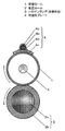
(実施の形態1)
図1は、本発明の実施の形態1における定着装置の概略構成を示す断面図であり、この定着装置は、複写機、プリンタ、FAX等の画像形成装置に用いられて、記録紙等の記録媒体上に付着したトナーを該記録媒体と共に加熱することで記録媒体上にトナー像を定着する熱ロール定着方式のものである。
(Embodiment 1)
FIG. 1 is a cross-sectional view showing a schematic configuration of a fixing device according to Embodiment 1 of the present invention. This fixing device is used in an image forming apparatus such as a copying machine, a printer, or a FAX, and records on recording paper or the like. This is a heat roll fixing system in which a toner image is fixed on a recording medium by heating the toner adhering to the medium together with the recording medium.
定着ロール1は、外径φ30mm、肉厚1mmのアルミニウムのパイプに、その表面にテフロン(登録商標)コーティングが施されたものであり、図示なき駆動手段により、回転駆動される。 定着ロール1と径方向(本実施形態では、上下方向)に対向する位置に加圧ロール2を備えている。加圧ロール2は、例えば、外径φ20mmのアルミニウム製の円柱状の基材2aと、この基材2aの外周面全周をその長さ方向略全体に亘って密着状態で覆う厚み5mmのシリコーンスポンジゴム2bと、このシリコーンスポンジゴム2bの外周面全周をその長さ方向略全体に亘って密着状態で覆う厚み30μmのテフロン(登録商標)チューブ(図示は省略している)とで構成されている。この加圧ロール2は、図示なき加圧手段により、定着ロール1に押し付けられるようになっている。この加圧ロール2は、定着ロール1の回転に伴い、従動回転するように支持されている。
The fixing roll 1 is an aluminum pipe having an outer diameter of 30 mm and a wall thickness of 1 mm, and the surface thereof is coated with Teflon (registered trademark), and is driven to rotate by a driving means (not shown). A
定着ロール1の内部には、記録媒体上のトナーを記録媒体と共に加熱するための加熱手段としてのハロゲンランプ3を備えている。そして、図示なき温度検知手段の検知温度に従い、ハロゲンランプ3のON・OFFを行い、定着ロール1が所望の温度(本実施の形態では170℃)に加熱、保温する。
Inside the fixing roll 1, a
定着ロール1の外周面には、この定着プレートに摺動するように均温化プレート4が配置されている。この均温化プレート4は、厚さ1mmの銅からなり、定着ロール1の外周面に倣うように、その内面の曲率が、定着ロール1の外径に対応させた高熱伝導プレート4aと、その高熱伝導プレート4aの外側に接触するよう配置された外径φ6mmのヒートパイプ4bと、そのヒートパイプ4bを高熱伝導プレート4aに押圧するよう配置したヒートパイプ押圧プレート4cと、高熱伝導プレート4aとヒートパイプ4cとの隙間を埋める熱伝導性の良好な充填剤4dとから構成されている。
On the outer peripheral surface of the fixing roll 1, a
高熱伝導プレート4aは、良好な熱伝導性が得られればどんな材料でも構わないが、本実施の形態では銅を用いている。また、その厚さは、伝熱量と熱容量との関係から、0.5mm〜3mmが好ましく、本実施の形態では1mmを用いている。
The high heat
ヒートパイプ押圧プレート4cは、良好な熱伝導性が要求され、銅を用いており、その厚さは、剛性と熱容量の観点から0.5mmを用いている。また、高熱伝導プレート4aとヒートパイプ押圧プレート4cとの固定方法は、溶接、ビス止め、接着、半田接続等が考えられるが、本実施の形態では溶接を用いている。
The heat
充填剤4dには、良好な熱伝導性が必要であり、本実施の形態では、金属粒子を含有したペースト材料を用いている。
The
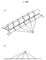
さらに、均温化プレート4には、図2に示すように溝部5を形成している。図2(a)は、均温化プレート4の斜視図、図2(b)は図2(a)のAA断面の断面図である。溝部の深さは、浅過ぎると撓み易くする効果が少ないため、銅プレート4aの厚さの10%以上あることが好ましく、本実施の形態では、0.5mmとしている。また、溝部の幅は、
広すぎると、その熱容量の差で温度むらが生じやすいため、狭い方が好ましい。具体的には、1mm以下さらには0.5mm以下が好ましく、本実施の形態では、0.1mmとしている。
Further, the
If it is too wide, temperature unevenness is likely to occur due to the difference in heat capacity. Specifically, it is preferably 1 mm or less, more preferably 0.5 mm or less, and in this embodiment, it is 0.1 mm.
次に動作について説明する。 Next, the operation will be described.
まず、図示なき手段により、定着ロール1を矢印の方向に回転させる。また、この定着ロール1の回転に伴って、加圧ロール2は矢印の方向に回転する。この状態で、ハロゲンランプ3を図示なき温度検出手段の検知温度にしたがって、ON・OFFし、定着ロール1の温度を170℃に加熱・保温する。この状態にて、未定着トナー画像が形成された記録紙を、定着ロール1と加圧ロール2とで形成されたニップを通過させることにより、未定着トナー画像を記録紙に定着することができる。
First, the fixing roll 1 is rotated in the direction of the arrow by means not shown. As the fixing roll 1 rotates, the
均温化プレート4は、定着ロール1と摺動する構成としている。均温化プレート4は、定着ロール1の軸方向への伝熱能力が非常に高いため、定着ロール1の軸方向の温度むらは非常に小さく抑えられる。A4サイズの記録紙の縦送り、200mm/secのプロセス速度の装置において、定着ロール1の温度を170℃に立ち上げた直後のA4サイズ内の軸方向の温度むらは±2℃に抑えることが出来た。
The
比較例として、均温化プレート4を備えない場合は、軸方向の温度むらは±7℃であり、中央部が端部より14℃高くなった。
As a comparative example, when the
さらに、比較例として、溝部5を形成していない均温化プレート4を用いた場合は、定着ロール1と均温化プレート4とは、端部よりも中央部の方が十分に接触するため、中央部の温度が上昇しにくく、結果的に、中央部の方が、端部よりも10℃低いという結果になった。
Further, as a comparative example, when the temperature-uniforming
この均温化プレート4は、定着ロール1との離接する構造も考えられるが、本実施の形態では、離間状態から当接した時の温度むらを防止することと装置構成を簡易にすることのため、当接したままとしている。
The
次に、小サイズ記録紙を通紙する場合の動作について説明する。 Next, an operation when passing a small size recording sheet will be described.
A4サイズ縦送りの装置に対し、小サイズ紙として、A5サイズを用い、この記録紙を縦方向で、200mm/secのプロセス速度において、40枚/分の速度で連続通紙での評価を実施した。 A5 size paper is used as a small size paper for the A4 size vertical feed device, and this recording paper is evaluated in a continuous direction at a process speed of 200 mm / sec at a speed of 40 sheets / min. did.
まず、ハロゲンランプ3をON・OFFさせ、通紙領域の温度が170℃になるように定着ロール1を加熱・保温する。その後、小サイズ記録紙を連続して通紙する。100枚連続通紙後の、非通紙領域の最高温度は190℃となり、通紙領域の170℃に対し、15℃の過昇温となった。この温度であれば、定着装置として全く問題なく使用可能である。 これに対し、均温プレート4を備えていない場合は、20枚の連続通紙で、過昇温が80℃となり、実験を中断した。
First, the
さらに、溝部5を形成していない均温化プレート4を用いた場合は、100枚の連続通紙で、過昇温が60℃となった。
Furthermore, when the temperature-uniforming
かかる構成によれば、均温化プレートには、その長手方向に対し非平行な方向に、溝部を形成したことにより、均温化プレートは、長手方向に撓み易く、定着ロールに均一に当接し易くなる。また、均温化プレートの長手方向に垂直な方向の断面積がほとんど変化せず、ヒートパイプへの伝熱量はほとんど低下しない。そして、均温化プレートの長手方向の伝熱は、伝熱能力の優れたヒートパイプを保持しているため、均温化プレート内の伝熱量を十分確保したまま、定着ロールに均一に当接することができ、定着ロールの端部の過昇温を低減することができる。 According to such a configuration, since the groove portion is formed in the temperature equalizing plate in a direction non-parallel to the longitudinal direction, the temperature equalizing plate is easily bent in the longitudinal direction and uniformly contacts the fixing roll. It becomes easy. Further, the cross-sectional area in the direction perpendicular to the longitudinal direction of the temperature equalizing plate hardly changes, and the amount of heat transfer to the heat pipe hardly decreases. And since the heat transfer in the longitudinal direction of the temperature equalizing plate holds a heat pipe with excellent heat transfer capability, it uniformly contacts the fixing roll while ensuring a sufficient amount of heat transfer in the temperature equalizing plate. It is possible to reduce overheating at the end of the fixing roll.
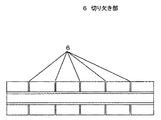
なお、本実施の形態では、均温化プレート4に溝部5を形成したが、図3のように高熱伝導プレート4aに切り欠き部を形成したものも好ましく用いることができる。この場合、高熱伝導プレート4aの長手方向の熱伝導は低下するが、均温化プレート4はヒートパイプ4bを備えたものであるため、長手方向の熱移動は、このヒートパイプ4bにてできるため、定着ロール1の端部の過昇温の低減は十分に行うことができる。なお、図3は、均温化プレート4を上面から見た図である。
In the present embodiment, the groove portion 5 is formed in the temperature-uniforming
また、本実施の形態では、溝部を、長手方向に垂直な方向としたが、これは、斜め方向であっても、効果は発揮できる。 Moreover, in this Embodiment, although the groove part was made into the direction perpendicular | vertical to a longitudinal direction, even if this is an oblique direction, an effect can be exhibited.
また、高熱伝導プレート4aの内側には何等表面処理等は実施しなかったが、定着ロール1と同様にテフロン(登録商標)コーティング処理を施すことも、定着ロール1と均温化プレート4との摺動性向上に効果があり、好ましく用いることができる。
Further, no surface treatment or the like was performed on the inner side of the high heat
また、本実施の形態では、加熱手段としてハロゲンランプ3を備えたが、これは、定着ロール1を加熱することができれば、どの様な手段でも構わない。
In this embodiment, the
また、本実施の形態において、定着ロール1を内包するベルトを用い、ベルトを介して加圧ロール2を定着ロール1に押圧する構成も好ましく用いられる。この場合、均温化プレートは、ベルトに当接する方法も、定着ロール1に当接する方法もどちらも用いることができる。さらに、MELT方式に様に、定着ロール1として、少なくとも2本のロールによりベルトを張架し、加圧ロールに加圧されない側のロールを加熱するものを用いる方法においては、ベルトを張架する2本のロールのどちらのロールに対して均温化プレート4を当接してもよく、また、直接ロールに当接するだけでなくベルトを介して押圧する構成も好ましく用いることができる。
In the present embodiment, a configuration in which a belt including the fixing roll 1 is used and the
また、本実施の形態では、加圧手段として加圧ロール2を用いたが、これは、例えば、FBNF(フリーベルトニップフューザー)の様な構成の加圧手段を用いても構わない。
In the present embodiment, the
(実施の形態2)
図4を用いて、本発明の実施の形態2の構成を説明する。
(Embodiment 2)
The configuration of the second embodiment of the present invention will be described with reference to FIG.
図4において、実施の形態1と異なるのは、均温化プレート4に溝部5の形成を施さず、
均温化プレートを2層構成としたものである。
In FIG. 4, the difference from the first embodiment is that the groove portion 5 is not formed on the
The soaking plate has a two-layer structure.
図4において、高熱伝導プレート4aは、第1層4aaと第2層4abとで構成されている。また、膜厚0.5mmの銅プレートで形成している。また、それらの形状は、定着ロール1の外周面に倣って良好に当接され、かつ、その状態で、第1層4aaと第2層4abとが、良好に密着するよう、曲率等を設計している。さらに、第1層4aaと第2層4abとの熱的接触が良好な様、両プレートの間に熱伝導性の良好な弾性体4acを介在させている。弾性体4acには、金属粒子を分散させたペーストや、シリコーン系、フッ素系を基材としたゴムなどが好ましく用いられる。
In FIG. 4, the high
本構成での動作について説明する。 The operation in this configuration will be described.
本実施の形態のように、同一材料、同一厚さの物を2層重ねた場合は、同一材料で、2倍の厚さの物を用いた場合に比較し、撓み易さは約4倍となる。一方、均温化プレート4内での伝熱量は、2層の均温化プレート4の接触面積を十分確保しさえすれば、基本的にはその均温化プレート4の断面積に依存することになり、2層のものでも、2倍の厚さの物でも略同じとなる。
As in this embodiment, when two layers of the same material and the same thickness are stacked, the ease of bending is about four times as compared with the case of using the same material and a thickness twice as much. It becomes. On the other hand, the amount of heat transfer in the
かかる構成によれば、均温化プレート4を2層とすることにより、均温化プレート4内の伝熱量の低下が少ない状態で、撓み易さを増加させることが可能となり、定着ロールの端部の過昇温を低減することができる。
According to such a configuration, by making the
また、かかる構成によれば、均温化プレート4を構成する2層のプレートの間に、熱伝導性の良好な弾性体4acを介在させたことにより、均温化プレート4の2層のプレート同士の十分な伝熱量を容易に確保することができる。
なお、本実施の形態では、高熱伝導プレート4aは2層で構成したが、これは、さらに3層等で形成しても構わない。
In addition, according to this configuration, the two-layer plate of the temperature-uniforming
In the present embodiment, the high thermal
(実施の形態3)
図5、図6を用いて、本発明の実施の形態3の構成を説明する。
(Embodiment 3)
The configuration of the third embodiment of the present invention will be described with reference to FIGS.
図5において、実施の形態1と異なるのは、定着ロール1として、薄肉のパイプを用いることと、それに伴い、定着ロール1に適した定着ロール支持部材7を備え、さらに、その薄肉パイプの軸方向の変形に伴い、均温化プレート4の形状を変更した事である。
In FIG. 5, the difference from the first embodiment is that a thin pipe is used as the fixing roll 1, and accordingly, a fixing
図5、図6を用いてその構成を詳しく説明する。 The configuration will be described in detail with reference to FIGS.
定着ロール1は、ステンレス鋼やリン青銅等のバネ性を有する金属からなり、加圧ロール2からの加圧力により弾性変形してその断面が円形状から、加圧ローラ2と定着ローラ1との対向方向(上下方向)が短軸でかつ水平方向が長軸である略楕円形状となる。本実施形態では、定着ロール1の外径はφ30mm、肉厚0.2mmのステンレス鋼(SUS304)を用いている。上記定着ロール1の両端部を除く外周面全周には、テフロン(登録商標)コーティングが施されている。
The fixing roll 1 is made of a metal having a spring property such as stainless steel or phosphor bronze, and is elastically deformed by a pressure applied from the
定着ロール1の両端部に対応する位置には、定着ロール支持部材7がそれぞれ配設されている。この各定着ロール支持部材7は、筒状の形状であり、その内径が、定着ロール1の外径より大きく、本実施の形態では、φ38mmとしている。また、定着ロール1が斜行するのを防止する当接部も定着ロール支持部材7には備えている。
Fixing
この定着ロール支持部材7は、軸受け8により回転自在に保持されており、図示ない駆動手段により、回転され、定着ロール1と定着ロール支持部材7よの摩擦力により、定着ロール1が回転駆動される。さらに、加圧ロール2は、定着ロール1の回転に伴って、従動駆動される。
The fixing
また、定着ロール1の加熱方法、そして、未定着画像が形成された記録紙を定着ロール1と加圧ロール2とで形成するニップを通過させ、記録紙にトナー像を定着させる動作は実施の形態1と全く同じである。
The heating method of the fixing roll 1 and the operation of fixing the toner image on the recording paper by passing the recording paper on which the unfixed image is formed through the nip formed by the fixing roll 1 and the
次に、均温化プレート4の動作について説明する。定着ロール1のニップとの反対側の曲率半径は、定着ロール1の端部は、略、定着ロール支持部材7の内面の曲率半径と同じであり、R19mmである。この状態を図6に示す。しかしながら、定着ロール1は薄肉パイプ材を用いているため、かつ、両端部のみで支持しているため、定着ロール1の端部と中央部とでは曲率が異なる。実測によれば、両端部の曲率半径19mmに対し、中央部の曲率半径17mmであった。したがって、本実施の形態では、均温化プレート4の定着ロール1に対向する部分の曲率半径を端部よりも中央部の方が、小さくなるようにし、均温化プレート4と定着ロール1とが均一に当接されるようにしている。
Next, the operation of the
かかる構成によれば、定着ロール1に薄肉パイプ材を用いたものであり、その定着ロール1の断面形状の変形に対応させ、均温化プレート4の定着ロール1に対向する側の曲率を、長手方向の中央部と端部とで異ならせたものであり、剛性の弱い定着ロール1に対しても、均温化プレート4を均一に当接することができ、これにより、定着ロール1の端部の過昇温を低減することができる。
According to this configuration, a thin pipe material is used for the fixing roll 1, and the curvature of the temperature-uniforming
なお、本実施の形態では、定着ロール保持部材7は、筒状の形状としたが、これは、定着ロール1を良好に回転駆動できるものであれば、例えば、半円弧状のものでも構わない。この場合は、加圧ロール2を回転駆動し、その回転に伴って定着ロール1を回転させるという方法が好ましい。
In the present embodiment, the fixing
なお、本実施の形態では、均温化プレート4を、定着ロール1のニップの反対側に当接したが、これは、別の場所に当接しても構わない。その場合は、均温化プレート4の定着ロール1に対向する側の曲率は、定着ロール1における均温化プレート4を当接する場所の曲率に対応させることは言うまでもない。
In this embodiment, the
本発明にかかる定着装置は、記録紙上に形成されたトナー像を定着するという効果を有し、複写機、FAX、プリンタ等の電子写真プロセスを利用した電子写真機器に適用される。 The fixing device according to the present invention has an effect of fixing a toner image formed on a recording paper, and is applied to an electrophotographic apparatus using an electrophotographic process such as a copying machine, a FAX, or a printer.
1 定着ロール
2 加圧ロール(加圧部材)
3 ハロゲンランプ(加熱手段)
4 均温化プレート
5 溝部
6 切り欠き部
7 定着ロール支持部材
1 fixing
3 Halogen lamp (heating means)
4 Soaking plate
5 Groove
Claims (6)
前記定着ロールを加熱する加熱手段と、
前記定着ロールに加圧される加圧手段と、
前記定着ロールの軸方向に長尺のものであり、その長手方向に対して垂直方向の断面で前記定着ロールと対向する側の形状が円弧状であり、前記定着ロールに加圧されることにより前記定着ロールの温度を均一にする、ヒートパイプを含んでなる均温化プレートとを備えたものであり、
前記均温化プレートには、その長手方向に対し非平行な方向に、少なくとも切り欠き部、または溝部を形成したことを特徴とする定着装置。 A fixing roll;
Heating means for heating the fixing roll;
A pressing means for pressing the fixing roll;
The fixing roll is long in the axial direction, and the shape on the side facing the fixing roll in a cross section perpendicular to the longitudinal direction is an arc shape, and is pressed by the fixing roll. A temperature equalizing plate including a heat pipe for making the temperature of the fixing roll uniform,
The fixing device according to claim 1, wherein at least a notch portion or a groove portion is formed in the temperature equalizing plate in a direction non-parallel to the longitudinal direction.
前記定着ロールを加熱する加熱手段と、
前記定着ロールに加圧される加圧手段と、
前記定着ロールの軸方向に長尺のものであり、その長手方向に対して垂直方向の断面で前記定着ロールに対向する側の形状が円弧状であり、前記定着ロールに加圧されることにより前記定着ロールの温度を均一にする、ヒートパイプを含んでなる均温化プレートとを備えたものであり、
前記均温化プレートは、前記定着ロールに対向する面に平行な面に複層構造としていることを特徴とする定着装置。 A fixing roll;
Heating means for heating the fixing roll;
A pressing means for pressing the fixing roll;
The fixing roll is long in the axial direction, and the shape on the side facing the fixing roll in a cross section perpendicular to the longitudinal direction is an arc shape, and is pressed by the fixing roll. A temperature equalizing plate including a heat pipe for making the temperature of the fixing roll uniform,
The fixing device according to claim 1, wherein the temperature equalizing plate has a multilayer structure on a surface parallel to a surface facing the fixing roll.
前記定着ロールを加熱する加熱手段と、
前記定着ロールに加圧される加圧手段と、
前記定着ロールの軸方向から見て前記定着ロールの外周面における前記加圧ロールと反対側の部分を覆うように略円弧状をなし、かつ前記反対側の部分を、前記定着ロールがそのロール軸回りに回転自在となるように支持する定着ロール支持部材と、
前記定着ロールの軸方向に長尺のものであり、その長手方向に対して垂直方向の断面で前記定着ロールと対向する側の形状が円弧状であり、前記定着ロールに加圧されることにより前記定着ロールの温度を均一にする、ヒートパイプを含んでなる均温化プレートとを備えたものであり、
前記定着ロールは、前記加圧手段による加圧力により断面形状が変形し、かつ、前記均温化プレートの前記定着ロールと対向する側は、前記定着ロールの断面形状の変形に対応させ、長手方向の中央部と端部とで曲率を異ならせたことを特徴とする定着装置。 A fixing roll made of thin-walled pipe material;
Heating means for heating the fixing roll;
A pressing means for pressing the fixing roll;
The fixing roll has a substantially arc shape so as to cover a portion of the outer peripheral surface of the fixing roll opposite to the pressure roll as viewed from the axial direction of the fixing roll, and the fixing roll has a roll shaft on the opposite side. A fixing roll support member that supports the roller so as to be freely rotatable,
The fixing roll is long in the axial direction, and the shape on the side facing the fixing roll in a cross section perpendicular to the longitudinal direction is an arc shape, and is pressed by the fixing roll. A temperature equalizing plate including a heat pipe for making the temperature of the fixing roll uniform,
The fixing roll has a cross-sectional shape deformed by the pressure applied by the pressurizing unit, and a side facing the fixing roll of the temperature equalizing plate corresponds to the deformation of the cross-sectional shape of the fixing roll, and is in the longitudinal direction. The fixing device is characterized in that the curvature is different between the central portion and the end portion.
Priority Applications (1)
| Application Number | Priority Date | Filing Date | Title |
|---|---|---|---|
| JP2006014864A JP2007199151A (en) | 2006-01-24 | 2006-01-24 | Fixing device |
Applications Claiming Priority (1)
| Application Number | Priority Date | Filing Date | Title |
|---|---|---|---|
| JP2006014864A JP2007199151A (en) | 2006-01-24 | 2006-01-24 | Fixing device |
Publications (1)
| Publication Number | Publication Date |
|---|---|
| JP2007199151A true JP2007199151A (en) | 2007-08-09 |
Family
ID=38453855
Family Applications (1)
| Application Number | Title | Priority Date | Filing Date |
|---|---|---|---|
| JP2006014864A Pending JP2007199151A (en) | 2006-01-24 | 2006-01-24 | Fixing device |
Country Status (1)
| Country | Link |
|---|---|
| JP (1) | JP2007199151A (en) |
Cited By (5)
| Publication number | Priority date | Publication date | Assignee | Title |
|---|---|---|---|---|
| JP2013250393A (en) * | 2012-05-31 | 2013-12-12 | Oki Data Corp | Fixing device and image forming apparatus |
| JP2014052460A (en) * | 2012-09-06 | 2014-03-20 | Canon Inc | Image forming apparatus |
| JP2017167460A (en) * | 2016-03-18 | 2017-09-21 | 株式会社リコー | Fixing device and image forming apparatus |
| JP2019045709A (en) * | 2017-09-04 | 2019-03-22 | 富士ゼロックス株式会社 | Fixing apparatus and image forming apparatus |
| US11092918B1 (en) | 2020-03-27 | 2021-08-17 | Fujifilm Business Innovation Corp. | Heating device and image forming apparatus including heat pipe having flat outer surface |
-
2006
- 2006-01-24 JP JP2006014864A patent/JP2007199151A/en active Pending
Cited By (5)
| Publication number | Priority date | Publication date | Assignee | Title |
|---|---|---|---|---|
| JP2013250393A (en) * | 2012-05-31 | 2013-12-12 | Oki Data Corp | Fixing device and image forming apparatus |
| JP2014052460A (en) * | 2012-09-06 | 2014-03-20 | Canon Inc | Image forming apparatus |
| JP2017167460A (en) * | 2016-03-18 | 2017-09-21 | 株式会社リコー | Fixing device and image forming apparatus |
| JP2019045709A (en) * | 2017-09-04 | 2019-03-22 | 富士ゼロックス株式会社 | Fixing apparatus and image forming apparatus |
| US11092918B1 (en) | 2020-03-27 | 2021-08-17 | Fujifilm Business Innovation Corp. | Heating device and image forming apparatus including heat pipe having flat outer surface |
Similar Documents
| Publication | Publication Date | Title |
|---|---|---|
| JP5633386B2 (en) | Fixing apparatus and image forming apparatus | |
| US7773931B2 (en) | Fusing device and image forming apparatus having the same | |
| US9915897B2 (en) | Fixing device | |
| JP6594043B2 (en) | Fixing device | |
| JP5530749B2 (en) | Fixing apparatus and image forming apparatus | |
| JP3807223B2 (en) | Fixing device | |
| JP2013073082A (en) | Fixing device | |
| JP2007199151A (en) | Fixing device | |
| JP2004037552A (en) | Fixing device | |
| JP2011095306A5 (en) | ||
| JP3142977B2 (en) | Heating equipment | |
| JP2002207380A (en) | Fixing device | |
| JP3818015B2 (en) | Image fixing device | |
| JP2007233424A (en) | Fixing device | |
| JP2005345859A (en) | Fixing device | |
| JP2005221712A (en) | Image fixing device | |
| JPH0764420A (en) | Heat fixing device | |
| JPH10115991A (en) | Pressure roller and heat fixing device | |
| JP4217746B2 (en) | Fixing device | |
| JP2005292548A (en) | Endless belt and fixing device | |
| JP2004286932A (en) | Belt fixing device | |
| JP4001759B2 (en) | Manufacturing method and manufacturing apparatus for resin-coated roller having smooth surface | |
| JP5955440B2 (en) | Fixing device | |
| JP2008233749A (en) | Material selection method for thin roller used in fixing device and fixing device using the thin roller | |
| JP6395472B2 (en) | Fixing device |