JP2007200701A - Luminaire - Google Patents
Luminaire Download PDFInfo
- Publication number
- JP2007200701A JP2007200701A JP2006017604A JP2006017604A JP2007200701A JP 2007200701 A JP2007200701 A JP 2007200701A JP 2006017604 A JP2006017604 A JP 2006017604A JP 2006017604 A JP2006017604 A JP 2006017604A JP 2007200701 A JP2007200701 A JP 2007200701A
- Authority
- JP
- Japan
- Prior art keywords
- lamp
- translucent cover
- reflection plate
- lighting fixture
- reflecting plate
- Prior art date
- Legal status (The legal status is an assumption and is not a legal conclusion. Google has not performed a legal analysis and makes no representation as to the accuracy of the status listed.)
- Withdrawn
Links
- 230000000694 effects Effects 0.000 abstract description 5
- 239000000463 material Substances 0.000 abstract description 3
- 230000002411 adverse Effects 0.000 abstract description 2
- 230000010354 integration Effects 0.000 abstract 1
- 230000003760 hair shine Effects 0.000 description 4
- 230000004048 modification Effects 0.000 description 4
- 238000012986 modification Methods 0.000 description 4
- 230000001788 irregular Effects 0.000 description 2
- NIXOWILDQLNWCW-UHFFFAOYSA-N acrylic acid group Chemical group C(C=C)(=O)O NIXOWILDQLNWCW-UHFFFAOYSA-N 0.000 description 1
- 230000005540 biological transmission Effects 0.000 description 1
- 238000009792 diffusion process Methods 0.000 description 1
- 239000002184 metal Substances 0.000 description 1
- 239000011347 resin Substances 0.000 description 1
- 229920005989 resin Polymers 0.000 description 1
- 230000000007 visual effect Effects 0.000 description 1
Images


Landscapes
- Non-Portable Lighting Devices Or Systems Thereof (AREA)
Abstract
Description
本発明は、ランプの周辺を覆う透光カバーが器具外観となる照明器具に関する。 The present invention relates to a lighting fixture in which a translucent cover that covers the periphery of a lamp has a fixture appearance.
従来のこの種の照明器具において、視覚的な光照射効果を高めるために、筒状の透光カバー内のランプ周辺に反射板を設け、その反射板を周方向に回転自在としたものがある(例えば、特許文献1参照)。
ところで、この種の照明器具のサイズを極力小さく抑えて小型化しようとすると、器具外観となる透光カバーとランプとの距離が短くなる。一方、透光カバーの部材は、一般に熱に弱い材質から構成されていることから、ランプの発熱がこの透光カバー部材に悪影響を与え易いものとなる。上記特許文献1の照明器具は、透光カバー内で反射板が回転し、ランプは反射板の内側で固定部材に固定された構成であるため、ランプを反射板寄りに配置して透光カバーへの熱の影響を少なくするといったことはできない。
By the way, when trying to reduce the size of this type of lighting fixture as much as possible, the distance between the translucent cover and the lamp, which is the appearance of the fixture, is shortened. On the other hand, since the member of the translucent cover is generally made of a material that is weak against heat, the heat generated by the lamp tends to adversely affect the translucent cover member. The lighting fixture of
本発明は、上記問題を解消するものであり、ランプの周辺が器具外観となる透光カバーで覆われていて、ランプと反射板が一体に回転可能で照射方向が可変な照明器具にあって、器具サイズを極力小さく抑えても、ランプ熱の透光カバーへの影響を低減できる照明器具を提供することを目的とする。 The present invention solves the above-described problem. In the lighting fixture in which the periphery of the lamp is covered with a light-transmitting cover that becomes the appearance of the fixture, the lamp and the reflector can be rotated together, and the irradiation direction is variable. An object of the present invention is to provide a lighting fixture that can reduce the influence of lamp heat on a light-transmitting cover even if the fixture size is kept as small as possible.
上記目的を達成するために、請求項1の発明は、ランプの周辺を覆う透光カバーが器具外観となる照明器具において、前記透光カバー内でランプとランプ光を所定方向に反射する反射板とが一体に回転軸回りに回転可能に設けられ、かつ、前記ランプは回転軸中心より反射板側寄りに配置されているものである。
In order to achieve the above object, the invention according to
請求項2の発明は、請求項1に記載の照明器具において、器具外観となる前記透光カバーが縦長の立方体形状であり、ランプソケットと反射板が一体となった部材が、前記縦長立方体形状に沿う一本の支柱に回転自在に支持されているものである。 According to a second aspect of the present invention, in the lighting apparatus according to the first aspect, the translucent cover that is an appearance of the apparatus has a vertically long cube shape, and a member in which the lamp socket and the reflector are integrated is the vertically long cube shape. Is rotatably supported by a single support along the line.
請求項3の発明は、請求項2に記載の照明器具において、ランプソケットと反射板が一体となった部材は回転軸に保持され、その回転軸の一端のみを前記支柱に保持させたものである。 According to a third aspect of the present invention, in the lighting apparatus according to the second aspect, the member in which the lamp socket and the reflecting plate are integrated is held by the rotating shaft, and only one end of the rotating shaft is held by the support column. is there.
請求項4の発明は、請求項3に記載の照明器具において、ランプソケットと反射板が一体となった部材を回転させるための操作部を備えているものである。 According to a fourth aspect of the present invention, there is provided the lighting apparatus according to the third aspect, further comprising an operation portion for rotating a member in which the lamp socket and the reflection plate are integrated.
請求項5の発明は、請求項1乃至請求項4のいずれかに記載の照明器具において、ランプソケットと反射板が一体となった部材は、光の照射方向を略170度以上回転可能で、任意の位置で固定可能としたものである。 According to a fifth aspect of the present invention, in the lighting apparatus according to any one of the first to fourth aspects, the member in which the lamp socket and the reflector are integrated can rotate the light irradiation direction by approximately 170 degrees or more. It can be fixed at an arbitrary position.
請求項6の発明は、請求項1乃至請求項5のいずれかに記載の照明器具において、前記反射板は、ランプの四方を覆う形状とされているものである。 According to a sixth aspect of the present invention, in the lighting apparatus according to any one of the first to fifth aspects, the reflecting plate has a shape that covers four sides of the lamp.
請求項1の発明によれば、透光カバー内で光の照射方向を可変でありながら、ランプ熱の透光カバーへの影響を低減できる照明器具を提供することができる。 According to the first aspect of the present invention, it is possible to provide a lighting apparatus that can reduce the influence of lamp heat on the light-transmitting cover while the light irradiation direction is variable in the light-transmitting cover.
請求項2、3の発明によれば、立方体形状の透光カバーの一面にだけ支柱の影が映り込むものとして影を低減でき、透光カバーの光り方が美しくなる。また、部品点数が少なくて済み、コストダウンが図れる。 According to the second and third aspects of the present invention, it is possible to reduce the shadow as if the shadow of the column is reflected only on one surface of the cubic-shaped translucent cover, and the light of the translucent cover becomes beautiful. Also, the number of parts can be reduced, and the cost can be reduced.
請求項4、5の発明によれば、透光カバーの光り方を変更する操作が容易となり、使い勝手とデザイン性の向上を図ることができる。 According to the fourth and fifth aspects of the invention, the operation of changing the way the translucent cover shines is facilitated, and the usability and design can be improved.
請求項6の発明によれば、透光カバーに映る反射板の影の明暗がくっきりするので、透光カバーの光り方が美しくなる。
According to the invention of
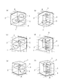
以下、本発明の一実施形態に係る照明器具について図面を参照して説明する。図1は、第1の実施形態による照明器具の各種取付状態を示す。この照明器具1は、器具外観が立方体形状とされている例であり、図1(a)(b)は照明器具1を天井6へ取付けた場合、(c)(d)は壁7へ取付けた場合、(e)(f)は床8へ据置いた場合を示している。
Hereinafter, the lighting fixture which concerns on one Embodiment of this invention is demonstrated with reference to drawings. FIG. 1 shows various attachment states of the luminaire according to the first embodiment. The
照明器具1は、ランプ4の周辺を覆い器具外観となる透光カバーである透光カバー2と、この透光カバー2内に設けられた、ランプ光を所定方向に反射させる反射板3及び発光するランプ4と、を備える。反射板3とランプ4(ランプソケットをも含め)は、一体に回転軸5回りに回転可能(図の矢印方向)な構成とされている。反射板3は、半裁した円筒形状で、裁断面に相当する面が開口し、両端が塞がれた樋状としている。反射板3は、この例に限られず、椀状のものであってもよい。ランプ4は、例えば60W白熱灯であり、上記のような反射板3に収納されており、回転軸5方向と同じ方向に取付けられ、発光熱の透光カバー2への影響を可及的に低減するため、回転軸5の中心より反射板3側寄りに配置される。一体と成った反射板3、ランプ4及び回転軸5は、図示していないフレーム(支柱)に支持され、使用に際し任意の角度に設定される。透光カバー2は、例えばアクリル透明樹脂製であり、取付け面以外が透光性であればよい。反射板3は、例えばミラー処理された金属板を用いる。
The
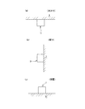
上記図1(a)(c)(e)は、回転軸5が水平方向、(b)(d)(f)は回転軸5が垂直方向の例を示す。図2(a)(b)(c)は、それぞれ、照明器具1を天井6へ取付けた場合、壁7へ取付けた場合、床8へ据置いた場合を示している。
FIGS. 1A, 1C, and 1E show examples in which the rotating
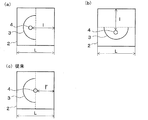
本実施形態の照明器具1によれば、ランプ熱の透光カバー2への影響を低減できるので、透光カバー2が比較的、熱の影響を受け易い材質で構成されていても、透光カバー2により覆われているランプ4と反射板3が一体に回転可能で照射方向を可変な器具をコンパクトに実現できる。ここで、図13を参照して、本発明の実施形態と従来品でのランプと透光カバーの距離の関係を説明する。従来品では、図13(c)に示すように、ランプ4と透光カバー2の距離l’は、透光カバー2の寸法Lの略半分となる。それに対して、本発明の実施形態においては、図13(a)(b)に示すように、照射方向が上向き、横向き等、いずれであっても、ランプ4と透光カバー2との距離lは、従来品の距離l’よりも大きくでき、ランプ2を透光カバー2から離すことができる。また、設計によっては、距離lは、透光カバー2の寸法Lの半分以上に大きくできる。
According to the
図3は、第1の実施形態の変形例に係る照明器具1を示し、器具外観となる透光カバー2が円柱形状とされている。その他の構成は、上記と同等である。
FIG. 3 shows a
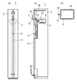
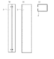
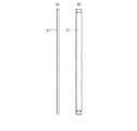
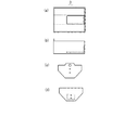
図4乃至図7は、第2の実施形態による照明器具1を示す。この照明器具1はスタンド型であって、図4(a)(b)(c)はその背面、側面透視、及び上面を、図5は透光カバー2を、図6は照明器具1の支柱を、図7は反射板を、それぞれ示す。照明器具1は、縦長立方体形状の透光カバー2と、縦長の支柱11と、ランプ4、ランプソケット13及び反射板3が一体になった可動部12と、を備える。可動部12は、回転軸5回りに回転させるための操作部となる操作レバー14付きの回転軸部材15に保持され、可動部12の一端側の回転軸部材15が支柱11に回転自在に支持されている。支柱11には、透光カバー2、透光パネル16、調光回路・調光スイッチ17等、殆どの部品が支持されている。ランプ4は、先の実施形態と同様に、回転軸5の中心より反射板3側寄りに配置される。
4 to 7 show the
可動部12は、光の照射方向を鉛直方向に略350度以上回転可能とされ、回転軸部材15に設けられた固定機構により任意の角度位置で固定される。反射板3は、図7に示されるように、ランプ4の四方を覆う、両端が塞がれた樋形状とされている。可動部12は、この例に限られず、光の照射方向を少なくとも略170度以上回転可能としたものであれば、実用に供することができる。
The
本実施形態の照明器具1によれば、前記実施形態と同様、透光カバー2への熱の影響を低減できる効果が得られるほか、ランプ4や反射板3等の殆どの部品を一本の支柱11に支持させ、立方体形状の透光カバー2の一面に沿って支柱が設けられた構造としたので、影として映り込んでくる部分を透光カバー2の一面のみとし、残りの3面には影が映りこまないようにすることができる。このため、透光カバー2の光り方が美しくなる。また、反射板3をランプ4の四方を覆う形状としたので、無駄な光の拡散を防ぐことができ、光の出方が美しくなる。さらにまた、一体になった可動部12がその一端側で支柱11に支持される構造であって、部品点数が少なくて済むので、コストダウンが図れる。また、透光カバー2の光り方を変更する操作が容易で、使い勝手とデザイン性の向上が図れる。
According to the
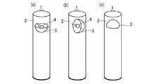
図8は、第2の実施形態の変形例に係る照明器具1を示す。この照明器具1は、器具外観となる透光カバー2が円柱形状で、スタンド型とされている。本実施形態においても、支柱は透光カバー2に沿って設けられている。同図(a)(b)(c)は、それぞれ光の照射方向を上向き、横向き、下向きとした状態を示す。
FIG. 8 shows a
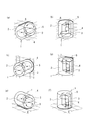
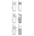
図9は、ランプ4の四方が反射板3に覆われていない場合の透光カバー2に映りこむ反射板3の影を示し、図10は、ランプ4の四方が反射板3に覆われている場合の透光カバー2に映りこむ影を示している。ここに、ランプ4の四方が反射板3に覆われていないものは、図示のように、反射板3の回転軸方向の一側端(支持側とは反対側)面が開口している例を示している。これらの図において、(a)(b)は光の照射方向が下向き、(c)(d)は光の照射方向が横向き、(e)(f)は光の照射方向が上向きの場合であり、斜線部がライト点灯時の反射板の陰を示す。ランプの四方が反射板に覆われていない場合は、影の形がいびつになり、透光カバー2の光り方が美しくないが、ランプの四方が反射板に覆われている場合は、陰の形がいびつにならず、しかも明暗がくっきりとして、透光カバー2の光り方が美しいものとなる。
FIG. 9 shows the shadow of the reflecting
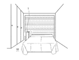
図11は、本実施形態の照明器具1が寝室のベッドサイドで使用される様子を示し、図12(a)(b)(c)は、シチュエーションに応じて配光を変更できる様子を示す。図12(a)は光の照射方向が上向きで、部屋全体の地灯り、(b)は横向きで、読書などタスク光、(c)は下向きの常夜灯(調光も可能)として、それぞれ用いる例を示している。斜線部分21,22,21は、光照射領域を示す。なお、本発明は、上記実施形態の構成に限られることなく、発明の趣旨を変更しない範囲で種々の変形が可能である。
FIG. 11 shows a state in which the
1 照明器具
2 透光カバー
3 反射板
4 ランプ
5 回転軸
11 支柱
12 可動部
13 ランプソケット
14 操作レバー(操作部)
15 回転軸部材
DESCRIPTION OF
15 Rotating shaft member
Claims (6)
前記透光カバー内でランプとランプ光を所定方向に反射する反射板とが一体に回転軸回りに回転可能に設けられ、かつ、前記ランプは回転軸中心より反射板側寄りに配置されていることを特徴とする照明器具。 In a lighting fixture in which a translucent cover covering the periphery of the lamp becomes the fixture appearance,
A lamp and a reflection plate that reflects the lamp light in a predetermined direction are provided so as to be rotatable around a rotation axis in the translucent cover, and the lamp is disposed closer to the reflection plate side than the rotation axis center. A lighting apparatus characterized by that.
ランプソケットと反射板が一体となった部材が、前記縦長立方体形状に沿う一本の支柱に回転自在に支持されていることを特徴とする請求項1に記載の照明器具。 The translucent cover that becomes the appearance of the appliance has a vertically long cubic shape,
The lighting fixture according to claim 1, wherein a member in which the lamp socket and the reflection plate are integrated is rotatably supported by a single support along the vertical cube shape.
Priority Applications (1)
| Application Number | Priority Date | Filing Date | Title |
|---|---|---|---|
| JP2006017604A JP2007200701A (en) | 2006-01-26 | 2006-01-26 | Luminaire |
Applications Claiming Priority (1)
| Application Number | Priority Date | Filing Date | Title |
|---|---|---|---|
| JP2006017604A JP2007200701A (en) | 2006-01-26 | 2006-01-26 | Luminaire |
Publications (1)
| Publication Number | Publication Date |
|---|---|
| JP2007200701A true JP2007200701A (en) | 2007-08-09 |
Family
ID=38455099
Family Applications (1)
| Application Number | Title | Priority Date | Filing Date |
|---|---|---|---|
| JP2006017604A Withdrawn JP2007200701A (en) | 2006-01-26 | 2006-01-26 | Luminaire |
Country Status (1)
| Country | Link |
|---|---|
| JP (1) | JP2007200701A (en) |
Cited By (1)
| Publication number | Priority date | Publication date | Assignee | Title |
|---|---|---|---|---|
| KR102613695B1 (en) * | 2023-05-15 | 2023-12-19 | 주식회사 선우엘 | Elevating type smart lighting fixture buried in the ground |
-
2006
- 2006-01-26 JP JP2006017604A patent/JP2007200701A/en not_active Withdrawn
Cited By (1)
| Publication number | Priority date | Publication date | Assignee | Title |
|---|---|---|---|---|
| KR102613695B1 (en) * | 2023-05-15 | 2023-12-19 | 주식회사 선우엘 | Elevating type smart lighting fixture buried in the ground |
Similar Documents
| Publication | Publication Date | Title |
|---|---|---|
| US10107480B1 (en) | Light fixture with pivoting sensor assembly | |
| JP4519148B2 (en) | Lighting device | |
| KR200454321Y1 (en) | Purchase for ceiling with adjustment function of irradiation range | |
| JP2009289709A (en) | Ceiling direct attachment type illumination device and illumination device | |
| JP2009009826A (en) | Lighting device | |
| US10082261B2 (en) | Pivotable light fixture | |
| JP4655952B2 (en) | lighting equipment | |
| JP2010146973A (en) | Lighting fixture | |
| WO2007133221A1 (en) | Nightlight with rotatable image drum | |
| JP2008016410A (en) | Lighting equipment for interior lighting | |
| JPH01309203A (en) | Space lighting apparatus | |
| EP1792119B1 (en) | Luminaire with louver members | |
| JP2015032428A (en) | LED lighting device | |
| JP2008210603A (en) | Recessed lighting fixture | |
| JP5756913B2 (en) | lighting equipment | |
| JP4316099B2 (en) | lighting equipment | |
| JP5840721B2 (en) | LED lighting device | |
| CN215982385U (en) | Lighting device | |
| JP4830926B2 (en) | Recessed lighting fixture | |
| KR100717994B1 (en) | Lamp cover rotary direct and indirect luminaire | |
| KR200408793Y1 (en) | Connection structure of main body and unit housing | |
| JP2011009059A (en) | Lighting device | |
| KR20090011959U (en) | Reflector such as ceiling | |
| TWI629432B (en) | Lamp | |
| KR960003171Y1 (en) | Ornament lighting |
Legal Events
| Date | Code | Title | Description |
|---|---|---|---|
| A300 | Withdrawal of application because of no request for examination |
Free format text: JAPANESE INTERMEDIATE CODE: A300 Effective date: 20090407 |