JP2007200719A - lighting equipment - Google Patents

lighting equipment Download PDF

Info

Publication number
JP2007200719A
JP2007200719A JP2006018192A JP2006018192A JP2007200719A JP 2007200719 A JP2007200719 A JP 2007200719A JP 2006018192 A JP2006018192 A JP 2006018192A JP 2006018192 A JP2006018192 A JP 2006018192A JP 2007200719 A JP2007200719 A JP 2007200719A
Authority
JP
Japan
Prior art keywords
light source
light
lighting
desk
source block
Prior art date
Legal status (The legal status is an assumption and is not a legal conclusion. Google has not performed a legal analysis and makes no representation as to the accuracy of the status listed.)
Pending
Application number
JP2006018192A
Other languages
Japanese (ja)
Inventor
Katsuyuki Kiyozumi
克行 清積
Current Assignee (The listed assignees may be inaccurate. Google has not performed a legal analysis and makes no representation or warranty as to the accuracy of the list.)
Panasonic Electric Works Co Ltd
Original Assignee
Matsushita Electric Works Ltd
Priority date (The priority date is an assumption and is not a legal conclusion. Google has not performed a legal analysis and makes no representation as to the accuracy of the date listed.)
Filing date
Publication date
Application filed by Matsushita Electric Works Ltd filed Critical Matsushita Electric Works Ltd
Priority to JP2006018192A priority Critical patent/JP2007200719A/en
Publication of JP2007200719A publication Critical patent/JP2007200719A/en
Pending legal-status Critical Current

Links

Images

Classifications

    • FMECHANICAL ENGINEERING; LIGHTING; HEATING; WEAPONS; BLASTING
    • F21LIGHTING
    • F21SNON-PORTABLE LIGHTING DEVICES; SYSTEMS THEREOF; VEHICLE LIGHTING DEVICES SPECIALLY ADAPTED FOR VEHICLE EXTERIORS
    • F21S6/00Lighting devices intended to be free-standing
    • F21S6/002Table lamps, e.g. for ambient lighting

Landscapes

  • Engineering & Computer Science (AREA)
  • General Engineering & Computer Science (AREA)
  • Non-Portable Lighting Devices Or Systems Thereof (AREA)

Abstract

【課題】主として机上面の1つの照射領域を照明しながらも、机上面における前記照射領域以外の場所も簡単に照明することができる照明器具を提供する。
【解決手段】照明器具は、LEDを用いた光源5を複数個有する主光源ブロック7と、主光源ブロック7とは別にLEDを用いた光源10を有する補助光源ブロック11と、机上面との対向面に開口部8,12が設けられ開口部8,12から光源5,10の光を出射させるように主光源ブロック7および補助光源ブロック11を収納する器具本体9とを備える。補助光源ブロック11は、光源10の光の出射方向を主光源ブロック7の光源5とは別に調節できるように、器具本体9に対して光源10を首振り可能に保持する首振り機構19を有する。
【選択図】図1
Provided is a lighting apparatus capable of easily illuminating a place other than the irradiation area on a desk top surface while illuminating mainly one irradiation area on the desk top surface.
A lighting fixture includes a main light source block having a plurality of light sources using LEDs, an auxiliary light source block having a light source using LEDs separately from the main light source block, and a desk surface. Opening portions 8 and 12 are provided on the surface, and a main body 9 for housing the main light source block 7 and the auxiliary light source block 11 is provided so that the light from the light sources 5 and 10 is emitted from the opening portions 8 and 12. The auxiliary light source block 11 has a swing mechanism 19 that holds the light source 10 so as to be swingable with respect to the instrument body 9 so that the light emission direction of the light source 10 can be adjusted separately from the light source 5 of the main light source block 7. .
[Selection] Figure 1

Description

本発明は、LEDを光源に用い、机上面を照明するように机に設置される照明器具に関するものである。   The present invention relates to a lighting fixture installed on a desk so as to illuminate a desk top surface using an LED as a light source.

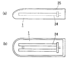
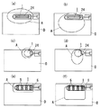
従来から、机上面を照明するように机に設置される照明器具として、蛍光灯あるいは白熱灯を光源に用いたものが主に提供されている。この種の照明器具は、図8に示すように、光源24(ここでは蛍光灯)の上方に反射板25を備え、光源24から上方に出射される光の配光を反射板25で制御している。なお、机に設置される照明器具は、一般的に、光源24を備える灯具1を可動式として、灯具1の水平方向の位置および水平面に対する角度を変えることにより、机上面において照明器具からの光が照射される照射領域の位置を調節できるように構成されている。たとえば光源24に蛍光灯を用いたものでは、灯具1の角度を変えることによって図9(a)、(b)のように机上面Dの照射領域Aが変化し、光源24に白熱灯を用いたものでは、灯具1の角度を変えることによって図9(c)、(d)のように机上面Dの照射領域Aが変化する。   2. Description of the Related Art Conventionally, as lighting fixtures installed on a desk so as to illuminate a desk top surface, those using a fluorescent lamp or an incandescent lamp as a light source are mainly provided. As shown in FIG. 8, this type of lighting fixture includes a reflector 25 above a light source 24 (here, a fluorescent lamp), and controls the light distribution of light emitted upward from the light source 24 by the reflector 25. ing. Note that a lighting fixture installed on a desk is generally configured such that the lamp 1 including the light source 24 is movable, and the light from the lighting fixture is changed on the desk top surface by changing the horizontal position of the lamp 1 and the angle with respect to the horizontal plane. It is comprised so that the position of the irradiation area | region irradiated with can be adjusted. For example, in the case where a fluorescent lamp is used as the light source 24, the irradiation area A of the desk surface D changes as shown in FIGS. 9A and 9B by changing the angle of the lamp 1, and an incandescent lamp is used as the light source 24. In this case, the irradiation area A on the desk surface D changes as shown in FIGS. 9C and 9D by changing the angle of the lamp 1.

一方、近年では様々な照明器具において、発光効率がよくかつ長寿命であるLED(発光ダイオード)を光源に用いたものが提案・提供されている。机に設置される上記照明器具においてもLEDを光源に用いることが望ましいと考えられており、このような照明器具も提案されている(たとえば特許文献1参照)。この種の照明器具は、灯具1として、図10に示すように光源5(LED)が実装された実装基板6と、下面に設けられた開口部8から光源5の光を出射させるように実装基板6を収納する器具本体9とを備えている。LEDは蛍光灯などに比べて発光面積が非常に小さいので、LEDを光源5に用いた上記照明器具では、図9(e)、(f)に示すように机上面Dの照射領域Aの全域に対して光源5からの光をむらなく照射するように、実装基板6の下面に光源5を適当な間隔で複数個配列する。
特開2004−103380号公報
On the other hand, in recent years, various lighting fixtures have been proposed / provided using light emitting diodes (LEDs) having high luminous efficiency and long life as light sources. It is thought that it is desirable to use LED as a light source also in the above-mentioned lighting fixture installed on a desk, and such a lighting fixture is also proposed (for example, refer patent document 1). This type of lighting fixture is mounted as a lamp 1 so that light from the light source 5 is emitted from a mounting substrate 6 on which a light source 5 (LED) is mounted as shown in FIG. An instrument body 9 for storing the substrate 6 is provided. Since the light emitting area of the LED is very small compared to a fluorescent lamp or the like, in the above-described lighting fixture using the LED as the light source 5, the entire irradiation area A of the desk surface D is shown in FIGS. 9 (e) and 9 (f). A plurality of light sources 5 are arranged on the lower surface of the mounting substrate 6 at appropriate intervals so that the light from the light sources 5 is evenly emitted to the substrate.
JP 2004-103380 A

ところで、上述したように机上面Dを照明する照明器具では、机上面Dの全面を照明するためには灯具1が大型となり邪魔になるので、灯具1を比較的小さくし机上面Dを部分的に照射領域Aとして照明するものが一般的である。しかし、机上面Dの一部分しか照明されていないと、照射領域A内での何らかの作業中に机上面Dにおける照射領域Aとは別の場所を一時的に照明する必要が生じた場合に、灯具1を移動させることにより照射領域Aを前記別の場所に移動させ、その後、灯具1を元の位置に移動させることにより照射領域Aを元の場所に戻す必要があるので面倒である。   By the way, in the lighting fixture that illuminates the desk top surface D as described above, the lamp 1 becomes large and obstructs in order to illuminate the entire surface of the desk top D. Therefore, the lamp 1 is relatively small and the desk top surface D is partially covered. In general, the illumination area A is illuminated. However, if only a part of the desk top surface D is illuminated, a lamp is required when it is necessary to temporarily illuminate a place other than the irradiation area A on the desk top surface D during some work in the irradiation area A. It is troublesome because it is necessary to move the irradiation area A to the other place by moving 1 and then return the irradiation area A to the original position by moving the lamp 1 to the original position.

本発明は上記事由に鑑みて為されたものであって、主として机上面の1つの照射領域を照明しながらも、机上面における前記照射領域以外の場所も簡単に照明することができる照明器具を提供することを目的とする。   The present invention has been made in view of the above circumstances, and is a lighting apparatus that can easily illuminate a place other than the irradiation area on the desk surface while mainly illuminating one irradiation area on the desk surface. The purpose is to provide.

請求項1の発明は、机上面を照明するように机に設置される照明器具であって、それぞれLEDを用いた複数個の光源と、机上面に対向する位置に配置されており、机上面との対向面に形成された開口部から光源の光を出射させるように前記複数個の光源を収納する器具本体と、器具本体に収納されており、前記複数個の光源のうちで光を一方向に出射するように配光制御された一部の光源を、当該光源の光の出射方向を他の光源とは別に変化させるように首振り可能に保持する首振り機構とを備えることを特徴とする。   The invention of claim 1 is a lighting device installed on a desk so as to illuminate the desk top surface, each of which is arranged at a position facing the desk top surface with a plurality of light sources using LEDs. An instrument body that houses the plurality of light sources so that light from the light source is emitted from an opening formed on a surface facing the instrument, and the instrument body. A swing mechanism that holds a part of the light source controlled to emit light in a direction so as to be swingable so as to change a light emission direction of the light source separately from other light sources. And

この構成によれば、首振り機構に保持された光源を首振り動作させることにより、首振り機構に保持された前記光源について他の光源とは別に光の出射方向を変化させることができるので、首振り機構に保持されていない光源によって机上面の1つの場所を照射領域として主に照明しながらも、机上面における当該照射領域以外の場所を首振り機構に保持された光源によって照明することができる。したがって、机上面の照射領域内での何らかの作業中に机上面における照射領域とは別の場所を一時的に照明する必要が生じた場合には、首振り機構に保持された光源を首振り動作させるだけで前記別の場所を簡単に照明することができる。   According to this configuration, by causing the light source held by the swing mechanism to swing, the light emission direction of the light source held by the swing mechanism can be changed separately from other light sources. While a light source not held by the swing mechanism mainly illuminates one place on the desk surface as an irradiation area, a place other than the irradiation area on the desk surface can be illuminated by a light source held by the swing mechanism. it can. Therefore, when it is necessary to temporarily illuminate a place other than the irradiation area on the desk surface during any work in the irradiation area on the desk surface, the light source held by the swing mechanism is swung. It is possible to easily illuminate the other place simply by making it.

請求項2の発明は、請求項1記載の発明において、前記首振り機構が、前記器具本体の定位置に固定される固定部材と、前記光源が固定されており固定部材に対して首振り可能に取り付けられる可動部材とを有することを特徴とする。   According to a second aspect of the present invention, in the first aspect of the invention, the swing mechanism includes a fixing member that is fixed to a fixed position of the instrument body, and the light source is fixed so that the swinging mechanism can swing relative to the fixing member. And a movable member attached to the head.

この構成によれば、可動部材を動かすだけの簡単な操作で、首振り機構に保持された光源を首振り動作させることができる。   According to this configuration, the light source held by the swing mechanism can be swung with a simple operation by simply moving the movable member.

請求項3の発明は、請求項1または請求項2の発明において、前記器具本体が前記机上面との対向面に沿った一方向に長い形状に形成されており、前記首振り機構が、器具本体における長手方向の両端部のうちの少なくとも一方に収納されていることを特徴とする。   According to a third aspect of the present invention, in the first or second aspect of the present invention, the instrument body is formed in a long shape in one direction along a surface facing the desk surface, and the swing mechanism is an instrument. It is housed in at least one of the longitudinal ends of the main body.

この構成によれば、首振り機構に保持された光源は、器具本体の長手方向の両端部のうちの少なくとも一方に配置されることになるので、首振り機構に保持された光源と、首振り機構に保持されていない光源とで、机上面において比較的離れた2箇所を照明することができる。   According to this configuration, since the light source held by the swing mechanism is disposed at at least one of the longitudinal ends of the instrument body, the light source held by the swing mechanism and the swing With a light source not held by the mechanism, it is possible to illuminate two places that are relatively far apart on the desk surface.

請求項4の発明は、請求項1ないし請求項3のいずれかの発明において、前記光源を点灯させる点灯回路を備え、点灯回路が、前記複数個の光源を全て点灯させる全点灯モードと、前記複数個の光源のうち前記首振り機構に保持されていない光源のみを点灯させる主点灯モードと、首振り機構に保持された光源のみを点灯させるスポット点灯モードとの3種類の動作モードを有することを特徴とする。   The invention of claim 4 comprises a lighting circuit for lighting the light source in any one of the inventions of claims 1 to 3, wherein the lighting circuit is a full lighting mode for lighting all of the plurality of light sources, and It has three types of operation modes: a main lighting mode that turns on only the light source that is not held by the swing mechanism among a plurality of light sources, and a spot lighting mode that turns on only the light source held by the swing mechanism. It is characterized by.

この構成によれば、机上面の1つの照射領域を照明すると同時に机上面における前記照射領域以外の場所も照明する場合には、全点灯モードで点灯回路を動作させ、それ以外の場合は、主点灯モードあるいはスポット点灯モードで点灯回路を動作させることにより、照明器具の省電力化を図ることができる。また、スポット点灯モードでは、机上面を局所的に照明することにより机上を装飾することも可能である。   According to this configuration, when illuminating one irradiation area on the desk surface and simultaneously illuminating a place other than the irradiation area on the desk surface, the lighting circuit is operated in the full lighting mode. By operating the lighting circuit in the lighting mode or the spot lighting mode, it is possible to save power in the lighting fixture. In the spot lighting mode, it is also possible to decorate the desk surface by locally illuminating the desk surface.

本発明は、首振り機構に保持された光源を首振り動作させ、当該光源の光の出射方向を調節することによって、首振り機構に保持された光源とその他の光源とで、別々の2箇所を照明することができる。すなわち、首振り機構に保持されていない光源によって机上面の1つの場所を照射領域として主に照明しながらも、机上面における当該照射領域以外の場所を首振り機構に保持された光源によって照明することができるという利点がある。したがって、机上面の照射領域内での何らかの作業中に机上面における照射領域とは別の場所を一時的に照明する必要が生じた場合には、首振り機構に保持された光源を首振り動作させるだけで前記別の場所を簡単に照明することができる。   In the present invention, the light source held by the swing mechanism is swung, and the light emission direction of the light source is adjusted to adjust the light source held by the swing mechanism and the other light sources at two separate locations. Can be illuminated. That is, while a light source not held by the swing mechanism mainly illuminates one place on the desk surface as an irradiation area, a place other than the irradiation area on the desk face is illuminated by a light source held by the swing mechanism. There is an advantage that you can. Therefore, when it is necessary to temporarily illuminate a place other than the irradiation area on the desk surface during any work in the irradiation area on the desk surface, the light source held by the swing mechanism is swung. It is possible to easily illuminate the other place simply by making it.

本実施形態の照明器具は、図2に示すように、机上に載置されるベース2と、基端部がベース2に固定されたアーム4と、アーム4の先端部に連結され机上面を照明可能な位置に支持される灯具1とを備えている。後述の光源を点灯させる点灯回路(図示せず)は、灯具1とベース2とアーム4とのいずれに収納されていてもよい。以下では、灯具1における光を出射する側の一面を机上面に平行させ、かつ灯具1の長手方向(図2の左右方向)を机上面の長手方向に一致させるように照明器具を机に設置したときの上下左右(図2の上下左右)を上下左右として説明する。アーム4は灯具1の右端部に連結されており、灯具1を、机上面に対して水平方向(前後左右)および垂直方向(上下)に移動可能かつアーム4の先端部を中心として首振り可能に支持することによって、灯具1の位置および灯具1の向きを調節可能としている。   As shown in FIG. 2, the lighting fixture of the present embodiment includes a base 2 placed on a desk, an arm 4 whose base end is fixed to the base 2, and a front end of the arm 4 connected to the tip of the arm 4. And a lamp 1 supported at a position where illumination is possible. A lighting circuit (not shown) for lighting a light source to be described later may be housed in any of the lamp 1, the base 2, and the arm 4. In the following, the lighting fixture is installed on the desk so that one surface of the lamp 1 on the light emitting side is parallel to the desk top surface and the longitudinal direction of the lamp 1 (the left-right direction in FIG. 2) coincides with the longitudinal direction of the desk top surface. The upper, lower, left, and right (up, down, left, and right in FIG. 2) will be described as up, down, left, and right. The arm 4 is connected to the right end of the lamp 1, can move the lamp 1 in the horizontal direction (front and rear left and right) and the vertical direction (up and down) with respect to the desk surface, and can swing around the tip of the arm 4. The position of the lamp 1 and the orientation of the lamp 1 can be adjusted.

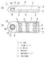
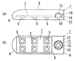
灯具1は、図1に示すように、LED(発光ダイオード)を用いた光源5が複数個(ここでは6個)実装されている実装基板6を備えた主光源ブロック7、および机上面との対向面となる下面の右端寄りに長方形状の開口部8が設けられ開口部8から光源5の光を出射させるように主光源ブロック7を収納する器具本体9とを有している。開口部8には光源5からの光を拡散透過させるパネルを設けてもよい。さらに、本実施形態の灯具1は主光源ブロック7とは別に、LEDを用いた光源10を備える補助光源ブロック11を有しており、この補助光源ブロック11においては器具本体9の下面の左端部に形成された円形状の開口部12から光源10の光を出射させるように器具本体9に収納される。詳しくは後述するが、補助光源ブロック11は、光源10の光の出射方向を主光源ブロック7の光源5とは別に調節できるように、器具本体9に対して光源10を首振り可能に保持する首振り機構19を有するものである。   As shown in FIG. 1, the lamp 1 includes a main light source block 7 including a mounting substrate 6 on which a plurality of (here, six) light sources 5 using LEDs (light emitting diodes) are mounted, and a desk surface. A rectangular opening 8 is provided near the right end of the lower surface serving as the opposing surface, and an instrument body 9 that houses the main light source block 7 so that the light from the light source 5 is emitted from the opening 8 is provided. A panel that diffuses and transmits light from the light source 5 may be provided in the opening 8. In addition to the main light source block 7, the lamp 1 of the present embodiment has an auxiliary light source block 11 including a light source 10 using LEDs. In the auxiliary light source block 11, the left end portion of the lower surface of the instrument body 9. Is stored in the instrument body 9 so that the light from the light source 10 is emitted from the circular opening 12 formed in the above. As will be described in detail later, the auxiliary light source block 11 holds the light source 10 in a swingable manner with respect to the instrument body 9 so that the light emission direction of the light source 10 can be adjusted separately from the light source 5 of the main light source block 7. A head swing mechanism 19 is provided.

器具本体9は、上下方向の寸法が最小となりかつ左右方向の寸法が最大となる箱状であって、左端部に丸みを帯びた形状に形成されている。このように器具本体9の上下方向の寸法を小さくできることも、蛍光灯や白熱灯に比べて小型であるLEDを光源5,10に用いたことによる利点である。主光源ブロック7においては、実装基板6は左右方向に長い長方形状に形成されている。この実装基板6は、主光源ブロック7の光源5(つまり実装基板6に実装された光源)を器具本体9に対して定位置に位置固定するものであって、器具本体9の長方形状の開口部8に対応する位置に固定される。実装基板6に実装された6個の光源5は、左右方向に等間隔で3個ずつ、前後に2列となるように実装基板6の下面に配列されている。   The instrument body 9 has a box shape in which the vertical dimension is minimum and the horizontal dimension is maximum, and is formed in a rounded shape at the left end. The fact that the vertical dimension of the fixture body 9 can be reduced in this way is also an advantage of using light sources 5 and 10 that are smaller in size than fluorescent lamps and incandescent lamps. In the main light source block 7, the mounting substrate 6 is formed in a rectangular shape that is long in the left-right direction. The mounting substrate 6 fixes the light source 5 of the main light source block 7 (that is, the light source mounted on the mounting substrate 6) in a fixed position with respect to the instrument main body 9, and has a rectangular opening in the instrument main body 9. The position corresponding to the portion 8 is fixed. The six light sources 5 mounted on the mounting substrate 6 are arranged on the lower surface of the mounting substrate 6 so that three light sources 5 are arranged at equal intervals in the left-right direction and are arranged in two rows in the front-rear direction.

本実施形態では各光源5,10はそれぞれ青色に発光するLEDチップ(図示せず)と、LEDチップを覆う光色変換部材(図示せず)とを備えている。光色変換部材は、透光性を有する透光性樹脂(たとえばシリコーン樹脂やエポキシ樹脂など)の中に、青色光を吸収することにより励起され黄色に発光する蛍光体を分散させたものであって、この光色変換部材に入射した光(青色光)のうち、一部の光は蛍光体で黄色光に変換されて出力され、その他の光は蛍光体に吸収されることなく光色変換部材を透過して青色光として出力されるので、光源から出射される光としては、互いに補色関係にある青色光と黄色光との混色光である白色光が得られることになる。   In the present embodiment, each of the light sources 5 and 10 includes an LED chip (not shown) that emits blue light and a light color conversion member (not shown) that covers the LED chip. The light color conversion member is a material in which a fluorescent material excited by absorbing blue light and emitting yellow light is dispersed in a light transmitting resin (for example, silicone resin or epoxy resin). Of the light (blue light) incident on this light color conversion member, part of the light is converted to yellow light by the phosphor and output, and the other light is light color converted without being absorbed by the phosphor. Since the light is transmitted through the member and output as blue light, white light that is a mixed color of blue light and yellow light that are complementary to each other is obtained as light emitted from the light source.

具体的に説明すると、各光源5,10はたとえばLEDチップをリードフレーム(図示せず)上に実装し、当該リードフレームを光色変換部材でモールドすることによりそれぞれ構成される。このとき、光色変換部材がレンズとしても機能し、LEDチップからの光を一方向に出射するように配光を制御する。ただし、白色光を得るための構成として、上述した光色変換部材を用いる構成に代えて、それぞれ発光色が異なる複数種類のLEDチップ(たとえば赤、緑、青の各色に発光する3種類のLEDチップ)を用い全LEDチップからの光を混色させる構成を採用してもよい。なお、白色光を出射する光源は本発明に用いる光源5,10の一例にすぎず、その他の発光色の光源を本発明に用いてもよい。たとえばLEDチップからの光が、色を変えることなくそのまま出射される光源を採用してもよい。   More specifically, each of the light sources 5 and 10 is configured by, for example, mounting an LED chip on a lead frame (not shown) and molding the lead frame with a light color conversion member. At this time, the light color conversion member also functions as a lens, and controls light distribution so that light from the LED chip is emitted in one direction. However, as a configuration for obtaining white light, instead of the configuration using the light color conversion member described above, a plurality of types of LED chips each having a different emission color (for example, three types of LEDs that emit light in red, green, and blue colors) A configuration in which light from all LED chips is mixed using a chip) may be employed. Note that the light source that emits white light is merely an example of the light sources 5 and 10 used in the present invention, and light sources of other emission colors may be used in the present invention. For example, you may employ | adopt the light source from which the light from an LED chip is radiate | emitted as it is, without changing a color.

ところで、補助光源ブロック11は、主光源ブロック7の左側方に位置するように、器具本体9の左端部に形成された開口部12に対応する位置に配置されている。図1に示す例では、補助光源ブロック11には光源10が1個だけ設けられており、これにより灯具1には合計7個の光源5,10が設けられることになる。   By the way, the auxiliary light source block 11 is disposed at a position corresponding to the opening 12 formed at the left end of the instrument body 9 so as to be located on the left side of the main light source block 7. In the example shown in FIG. 1, only one light source 10 is provided in the auxiliary light source block 11, so that a total of seven light sources 5 and 10 are provided in the lamp 1.

以下に、補助光源ブロック11の具体的な構成について図3を参照して説明する。   A specific configuration of the auxiliary light source block 11 will be described below with reference to FIG.

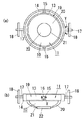
図3に示す補助光源ブロック11は、一面側に光源10が固定される円盤状の可動部材13と、環状に形成された可動枠14と、器具本体9における開口部12の周縁から上方に突出する形で器具本体9に固定された一対の固定部材18とを有しており、可動部材13の周面の前後両端部には、前方および後方にそれぞれ突出する一対の内側回転軸15が形成されている。可動部材13は前記一対の内側回転軸15を、可動枠14に形成された一対の内側軸受孔16に挿入することによって、可動枠14内に内側回転軸15を軸として図3(b)のX方向に首振り可能に支持される。さらに、可動枠14の左右両端部には両側方に一対の外側回転軸17が突設されており、これら外側回転軸17を、器具本体9と一体に設けられた固定部材18の外側軸受孔(図示せず)に挿入することによって、可動部材13は、固定部材18に対して外側回転軸17を軸として図3(a)のY方向に首振り可能に支持される。   The auxiliary light source block 11 shown in FIG. 3 protrudes upward from the peripheral edge of the opening 12 in the instrument main body 9, a disc-shaped movable member 13 to which the light source 10 is fixed on one surface side, a movable frame 14 formed in an annular shape. A pair of fixing members 18 fixed to the instrument body 9 is formed, and a pair of inner rotating shafts 15 projecting forward and backward are formed at both front and rear ends of the peripheral surface of the movable member 13. Has been. The movable member 13 inserts the pair of inner rotating shafts 15 into a pair of inner bearing holes 16 formed in the movable frame 14, thereby allowing the inner rotating shaft 15 to be an axis in the movable frame 14 as shown in FIG. Supported to swing in the X direction. Further, a pair of outer rotating shafts 17 project from both left and right end portions of the movable frame 14, and these outer rotating shafts 17 are connected to outer bearing holes of a fixing member 18 provided integrally with the instrument body 9. By inserting in (not shown), the movable member 13 is supported so as to be able to swing in the Y direction of FIG.

上述した構成により、可動部材13は、固定部材18に対して内側回転軸15と外側回転軸17との各々を軸として首振り可能に支持されることになる。すなわち、可動部材13と固定部材18とで、補助光源ブロック11の光源10を器具本体9に対して首振り可能に保持する首振り機構19が構成される。ここで、内側軸受孔16および外側軸受孔は、光源10の首振り時に、それぞれ内側回転軸15および外側回転軸17との間に摩擦力を生じるように寸法が設定されており、この摩擦力によって光源10は任意の首振り角度で保持されることになる。その結果、補助光源ブロック11の光源10は可動部材13の首振り可能な範囲内において光の出射方向が変化することとなり、補助光源ブロック11の光源10の光の出射方向を主光源ブロック7の光源5とは別に調節可能となる。なお、図3に示す補助光源ブロック11は補助光源ブロック11の一例にすぎず、たとえば図1に示すように、器具本体9に固定される固定部材18を下面開口の半球状に形成し、可動部材13も半球状に形成し、固定部材18内に可動部材13を嵌め込むとともに可動部材13の下面側に光源10を固定することにより補助光源ブロック11を構成してもよい。この構成では、可動部材13を固定部材18内で回動させることによって補助光源ブロック11の光源10の光の出射方向が変化する。   With the above-described configuration, the movable member 13 is supported so as to be swingable with respect to the fixed member 18 about the inner rotary shaft 15 and the outer rotary shaft 17 as axes. That is, the movable member 13 and the fixed member 18 constitute a swing mechanism 19 that holds the light source 10 of the auxiliary light source block 11 with respect to the instrument body 9 so as to be swingable. Here, the inner bearing hole 16 and the outer bearing hole are sized so as to generate a frictional force between the inner rotary shaft 15 and the outer rotary shaft 17 when the light source 10 is swung. Thus, the light source 10 is held at an arbitrary swing angle. As a result, the light emission direction of the light source 10 of the auxiliary light source block 11 changes within the range in which the movable member 13 can swing, and the light emission direction of the light source 10 of the auxiliary light source block 11 is changed to that of the main light source block 7. The light source 5 can be adjusted separately. The auxiliary light source block 11 shown in FIG. 3 is merely an example of the auxiliary light source block 11. For example, as shown in FIG. 1, the fixing member 18 fixed to the instrument main body 9 is formed in a hemispherical shape with a lower surface opening and is movable. The auxiliary light source block 11 may be configured by forming the member 13 in a hemispherical shape, fitting the movable member 13 in the fixed member 18, and fixing the light source 10 to the lower surface side of the movable member 13. In this configuration, the light emitting direction of the light source 10 of the auxiliary light source block 11 is changed by rotating the movable member 13 within the fixed member 18.

また、図3においては、各光源5,10に上述した構成(リードフレームを光色変換部材でモールドした構成)とは別の構成をそれぞれ採用しており、可動部材13の一面側に実装されたLEDチップを、一面開口の半球状に形成されたカバー体20で包囲することにより光源10が構成されている。カバー体20は、半球の頂点部分に可動部材13の厚み方向に貫通する窓孔21が形成されており、窓孔21が出射窓22によって閉塞されている。出射窓22は光色変換部材から形成されており、LEDチップからの光がこの出射窓を通してカバー体20と可動部材13とで囲まれた空間の外部に出射されることにより、白色光が得られることになる。ここで、光源10の光は出射窓22から一方向に出射されることになる。   In FIG. 3, each of the light sources 5 and 10 adopts a configuration different from the above-described configuration (configuration in which a lead frame is molded with a light color conversion member), and is mounted on one surface side of the movable member 13. The light source 10 is configured by surrounding the LED chip with a cover body 20 formed in a hemispherical shape with one opening. The cover body 20 is formed with a window hole 21 penetrating in the thickness direction of the movable member 13 at the apex portion of the hemisphere, and the window hole 21 is closed by the emission window 22. The exit window 22 is formed of a light color conversion member, and white light is obtained by emitting light from the LED chip to the outside of the space surrounded by the cover body 20 and the movable member 13 through the exit window. Will be. Here, the light from the light source 10 is emitted in one direction from the emission window 22.

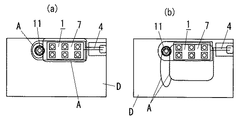
図4および図5は、本実施形態の照明器具を用いて机上面Dを照明したときの机上面Dの照射領域Aを示す図である。図4(a)は、補助光源ブロック11の光源10を真下に向けた状態、つまり補助光源ブロック11の光源10と主光源ブロック7の光源5との光の出射方向を一方向に揃えた状態で、実装基板6が机上面Dに平行となるように灯具1を支持したときの図であって、このとき、机上面Dにおいては灯具1に対向する部位が照射領域Aとして照明される。図4(b)は、図4(a)の状態から、補助光源ブロック11を動かさずに、実装基板6の前端部を上げるように灯具1を手前(図の下方)に傾けたときの図であって、このとき、机上面Dにおいては灯具1の前方部位が照射領域Aとして照明される。   4 and 5 are diagrams showing an irradiation area A of the desk top surface D when the desk top surface D is illuminated using the lighting fixture of the present embodiment. FIG. 4A shows a state in which the light source 10 of the auxiliary light source block 11 is directed downward, that is, a state in which the light emission directions of the light source 10 of the auxiliary light source block 11 and the light source 5 of the main light source block 7 are aligned in one direction. FIG. 6 is a view when the lamp 1 is supported so that the mounting substrate 6 is parallel to the desk surface D. At this time, a portion of the desk surface D facing the lamp 1 is illuminated as the irradiation region A. 4B is a view when the lamp 1 is tilted forward (downward in the drawing) so as to raise the front end of the mounting substrate 6 without moving the auxiliary light source block 11 from the state of FIG. 4A. In this case, the front portion of the lamp 1 is illuminated as the irradiation area A on the desk surface D.

一方、図5(a)は、灯具1を図4(a)と同じ配置とし、補助光源ブロック11の光源10の前端部を上げるように補助光源ブロック11の光源10を手前(図の下方)に傾けたときの図であって、このとき、机上面Dにおいては灯具1の主光源ブロック7に対向する部位と、補助光源ブロック11の前方部位とが照射領域Aとして照明される。図5(b)は、灯具1を図4(b)と同じ配置とし、補助光源ブロック11の光源10の左端部を上げるように補助光源ブロック11の光源10を左に傾けたときの図であって、このとき、机上面Dにおいては灯具1の主光源ブロック7の前方部位と、補助光源ブロック11の左斜め前方部位とが照射領域Aとして照明される。   On the other hand, in FIG. 5A, the lamp 1 is arranged in the same manner as in FIG. 4A, and the light source 10 of the auxiliary light source block 11 is in front (lower in the drawing) so that the front end of the light source 10 of the auxiliary light source block 11 is raised. In this case, on the desk surface D, the part facing the main light source block 7 of the lamp 1 and the front part of the auxiliary light source block 11 are illuminated as the irradiation area A. FIG. 5B is a diagram when the lamp 1 is arranged in the same manner as FIG. 4B and the light source 10 of the auxiliary light source block 11 is tilted to the left so as to raise the left end of the light source 10 of the auxiliary light source block 11. At this time, on the desk surface D, the front portion of the main light source block 7 of the lamp 1 and the left front portion of the auxiliary light source block 11 are illuminated as the irradiation region A.

このように、本実施形態では、補助光源ブロック11の光源10を傾けて当該光源10の光の出射方向を調節することによって、主光源ブロック7の光源7と補助光源ブロック11の光源10とで机上面Dの1つの場所を照射領域Aとして照明したり(図4参照)、主光源ブロック7の光源7で机上面Dの1つの場所を照射領域Aとして主に照明しながらも、補助光源ブロック11の光源10により光源5とは別の場所を照明したり(図5参照)することができる。したがって、机上面Dの照射領域A内での何らかの作業中に机上面Dにおける前記照射領域Aとは別の場所を一時的に照明する必要が生じた場合、たとえば机上面Dの中央付近で本を読んでいる最中に机上面Dの左端付近にあるスケジュール表を見る場合などには、器具本体9に対して全ての光源が固定された従来の照明器具のように灯具1自体を一時的に移動させる必要はなく、補助光源ブロック11の光源10を傾けるだけで前記別の場所を簡単に照明することができる。主光源ブロック7の光源7と補助光源ブロック11の光源10とで机上面Dの別々の場所を同時に照明することもできるから、たとえば、机上面Dの左端付近に置かれた本と机上面の中央付近に置かれたキーボードとの両方を同時に照明することにより、本を見ながらキーボードを操作するというような使い方もできる。   Thus, in the present embodiment, the light source 10 of the main light source block 7 and the light source 10 of the auxiliary light source block 11 are adjusted by tilting the light source 10 of the auxiliary light source block 11 and adjusting the light emission direction of the light source 10. While illuminating one place on the desk top surface D as the irradiation area A (see FIG. 4) or mainly illuminating one place on the desk top surface D as the irradiation area A with the light source 7 of the main light source block 7, the auxiliary light source A place different from the light source 5 can be illuminated by the light source 10 of the block 11 (see FIG. 5). Accordingly, when it is necessary to temporarily illuminate a place other than the irradiation area A on the desk top surface D during some work in the irradiation area A on the desk top surface D, for example, a book near the center of the desk top surface D is used. When reading a schedule table near the left end of the desk surface D while reading the lamp, the lamp 1 itself is temporarily placed like a conventional lighting fixture in which all light sources are fixed to the fixture body 9. It is not necessary to move the light source 10 to the auxiliary light source block 11, and it is possible to easily illuminate the other place simply by tilting the light source 10 of the auxiliary light source block 11. Since the light source 7 of the main light source block 7 and the light source 10 of the auxiliary light source block 11 can simultaneously illuminate different places on the desk top surface D, for example, a book placed near the left end of the desk top surface D and the desk top surface By illuminating both the keyboard placed near the center at the same time, you can operate the keyboard while watching a book.

また、従来の照明器具では、灯具1を傾けるだけで所望の配光が得られなければ、灯具1を水平方向(前後左右)に移動させる必要があるが、本実施形態の照明器具では、灯具1を傾けるだけで所望の配光が得られなくとも、補助光源ブロック11の光源10を傾けることによって所望の配光が得られることが多々ある(たとえば図5(b))ので、従来の照明器具に比べて灯具1を水平方向に移動させる必要性は低い。要するに、本実施形態では灯具1を机上面Dの後端部に寄せたままでも多様な配光を実現することができ、灯具1が使用者の頭部に近接して邪魔になることを回避できるという利点がある。なお、図4および図5は照明器具の使用形態の一例にすぎず、ここで示した他にも灯具1の配置および補助光源ブロック11の光源10の向きによって様々な照射領域を実現することが可能である。   In the conventional lighting fixture, if the desired light distribution cannot be obtained by simply tilting the lighting fixture 1, it is necessary to move the lighting fixture 1 in the horizontal direction (front / rear / left / right). Even if the desired light distribution cannot be obtained simply by tilting 1, the desired light distribution is often obtained by tilting the light source 10 of the auxiliary light source block 11 (for example, FIG. 5B). It is less necessary to move the lamp 1 in the horizontal direction compared to the fixture. In short, in the present embodiment, various light distributions can be realized even when the lamp 1 is brought close to the rear end of the desk surface D, and the lamp 1 is prevented from getting in the vicinity of the user's head. There is an advantage that you can. 4 and FIG. 5 are only examples of usage patterns of the lighting fixtures, and other than those shown here, various irradiation areas can be realized depending on the arrangement of the lamp 1 and the direction of the light source 10 of the auxiliary light source block 11. Is possible.

ところで、光源5,10を点灯させる点灯回路は、7個の光源5,10を全て同時に点灯させる全点灯モードのほか、主光源ブロック7の光源5のみを点灯させる主点灯モード、および補助光源ブロック11の光源10のみを点灯させるスポット点灯モードでも動作できる構成とすることが望ましい。この構成によれば、全点灯モードにおいては上述したように主光源ブロック7の光源7と補助光源ブロック11の光源10とで机上面Dの別々の場所を同時に照明するなどの使い方が可能であり、さらに、主光源ブロック7の光源5と補助光源ブロック11の光源10とのいずれか一方のみで所望の照射領域Aを実現可能な場合には、それぞれ主点灯モード、またはスポット点灯モードで動作させることによって照明器具の省電力化が図れる。特に、スポット点灯モードにおいては、たとえば机上に存在する特定の物体を照明することにより、装飾的な照明として照明器具を使用することができる。   By the way, the lighting circuit for lighting the light sources 5 and 10 includes a main lighting mode for lighting only the light source 5 of the main light source block 7 and an auxiliary light source block in addition to the all lighting mode for lighting all the seven light sources 5 and 10 simultaneously. It is desirable to be able to operate even in a spot lighting mode in which only 11 light sources 10 are lit. According to this configuration, in the full lighting mode, as described above, the light source 7 of the main light source block 7 and the light source 10 of the auxiliary light source block 11 can illuminate different places on the desk surface D at the same time. Further, when a desired irradiation area A can be realized by only one of the light source 5 of the main light source block 7 and the light source 10 of the auxiliary light source block 11, the operation is performed in the main lighting mode or the spot lighting mode, respectively. As a result, it is possible to save power in the lighting fixture. In particular, in the spot lighting mode, a lighting fixture can be used as decorative lighting, for example, by illuminating a specific object existing on a desk.

また、灯具1において補助光源ブロック11を設ける位置は、上述したように主光源ブロック7の左側方(器具本体9の左端部)に限るものではなく、図6に示すように主光源ブロック7を器具本体9の左端寄りに配置し、主光源ブロック7の右側方(器具本体9の右端部)に補助光源ブロック11を設けるようにしてもよい。さらに、補助光源ブロック11を複数個設けてもよく、この場合には、たとえば図7に示すように主光源ブロック7の左右両側方にそれぞれ補助光源ブロック11を設けることが望ましい。1個の補助光源ブロック11に複数個の光源10を設け、各補助光源ブロック11の光出力をそれぞれ増大させてもよい。主光源ブロック7に設ける光源5の個数もまた任意に設定される。   Further, the position where the auxiliary light source block 11 is provided in the lamp 1 is not limited to the left side of the main light source block 7 (the left end portion of the fixture body 9) as described above, but the main light source block 7 is arranged as shown in FIG. The auxiliary light source block 11 may be provided near the left end of the instrument main body 9 and provided on the right side of the main light source block 7 (right end of the instrument main body 9). Further, a plurality of auxiliary light source blocks 11 may be provided. In this case, for example, as shown in FIG. 7, it is desirable to provide the auxiliary light source blocks 11 on both the left and right sides of the main light source block 7, respectively. A plurality of light sources 10 may be provided in one auxiliary light source block 11 to increase the light output of each auxiliary light source block 11. The number of light sources 5 provided in the main light source block 7 is also arbitrarily set.

なお、上記実施形態では、照明器具としてベース2を有し机上に載置されるスタンドを例示したが、この構成に限るものではなく、たとえば、ベース2に代えて机の天板の周部を挟持する固定部(図示せず)を備える照明器具や、灯具1が机に一体に取り付けられる照明器具などに本発明を適用してもよい。   In the above-described embodiment, the stand having the base 2 as the lighting fixture is exemplified. However, the stand is not limited to this configuration. For example, instead of the base 2, the peripheral portion of the top plate of the desk is used. You may apply this invention to a lighting fixture provided with the fixing | fixed part (not shown) clamped, a lighting fixture with which the lamp 1 is attached to a desk integrally, etc.

本発明の実施形態の灯具を示し、(a)は側面図、(b)は下面図である。The lamp | ramp of embodiment of this invention is shown, (a) is a side view, (b) is a bottom view. 同上の照明器具を示す側面図である。It is a side view which shows a lighting fixture same as the above. 同上の補助光源ブロックの一例を示し、(a)は下面図、(b)は側面図である。An example of an auxiliary light source block same as the above is shown, (a) is a bottom view, and (b) is a side view. 同上の照明器具を用いて机上面を照明したときの机上面の照射領域を示す上面図である。It is a top view which shows the irradiation area | region of the desk upper surface when the desk upper surface is illuminated using the lighting fixture same as the above. 同上の照明器具を用いて机上面を照明したときの机上面の照射領域を示す上面図である。It is a top view which shows the irradiation area | region of the desk upper surface when the desk upper surface is illuminated using the lighting fixture same as the above. 同上の灯具の他の構成を示し、(a)は側面図、(b)は下面図である。The other structure of a lamp | ramp same as the above is shown, (a) is a side view, (b) is a bottom view. 同上の灯具のさらに他の構成を示し、(a)は側面図、(b)は下面図である。The other structure of the lamp | ramp same as the above is shown, (a) is a side view, (b) is a bottom view. 従来例を示し、(a)は側面図、(b)は下面図である。A prior art example is shown, (a) is a side view, (b) is a bottom view. 同上の照明器具を用いて机上面を照明したときの机上面の照射領域を示す上面図である。It is a top view which shows the irradiation area | region of the desk upper surface when the desk upper surface is illuminated using the lighting fixture same as the above. 他の従来例を示し、(a)は側面図、(b)は下面図である。Another prior art example is shown, (a) is a side view and (b) is a bottom view.

符号の説明Explanation of symbols

5,10 光源
8,12 開口部
9 器具本体
13 可動部材
18 固定部材
19 首振り機構
D 机上面
5, 10 Light source 8, 12 Opening 9 Instrument body 13 Movable member 18 Fixed member 19 Swing mechanism D Desk top

Claims (4)

机上面を照明するように机に設置される照明器具であって、それぞれLEDを用いた複数個の光源と、机上面に対向する位置に配置されており、机上面との対向面に形成された開口部から光源の光を出射させるように前記複数個の光源を収納する器具本体と、器具本体に収納されており、前記複数個の光源のうちで光を一方向に出射するように配光制御された一部の光源を、当該光源の光の出射方向を他の光源とは別に変化させるように首振り可能に保持する首振り機構とを備えることを特徴とする照明器具。   A lighting fixture installed on a desk so as to illuminate the desk top surface, each of which is arranged at a position facing the desk top surface and a plurality of light sources using LEDs, and formed on a surface facing the desk top surface. An instrument body that houses the plurality of light sources so that light from the light source is emitted from the opening, and the instrument body, and is arranged to emit light in one direction among the plurality of light sources. An illuminating apparatus comprising: a swing mechanism that holds a part of the light source that is light-controlled so as to be swingable so as to change a light emission direction of the light source separately from other light sources. 前記首振り機構は、前記器具本体の定位置に固定される固定部材と、前記光源が固定されており固定部材に対して首振り可能に取り付けられる可動部材とを有することを特徴とする請求項1記載の照明器具。   The swing mechanism includes a fixed member that is fixed to a fixed position of the instrument body, and a movable member that is fixed to the light source and is swingably attached to the fixed member. The lighting fixture according to 1. 前記器具本体は前記机上面との対向面に沿った一方向に長い形状に形成されており、前記首振り機構は、器具本体における長手方向の両端部のうちの少なくとも一方に収納されていることを特徴とする請求項1または請求項2に記載の照明器具。   The instrument main body is formed in a long shape in one direction along the surface facing the desk top surface, and the swing mechanism is housed in at least one of the longitudinal ends of the instrument main body. The lighting fixture according to claim 1 or 2, characterized by the above. 前記光源を点灯させる点灯回路を備え、点灯回路は、前記複数個の光源を全て点灯させる全点灯モードと、前記複数個の光源のうち前記首振り機構に保持されていない光源のみを点灯させる主点灯モードと、首振り機構に保持された光源のみを点灯させるスポット点灯モードとの3種類の動作モードを有することを特徴とする請求項1ないし請求項3のいずれか1項に記載の照明器具。   A lighting circuit for lighting the light source, the lighting circuit lighting only a light source that is not held by the swing mechanism among the plurality of light sources; The lighting apparatus according to any one of claims 1 to 3, wherein the lighting apparatus has three types of operation modes: a lighting mode and a spot lighting mode in which only a light source held by the swing mechanism is turned on. .
JP2006018192A 2006-01-26 2006-01-26 lighting equipment Pending JP2007200719A (en)

Priority Applications (1)

Application Number Priority Date Filing Date Title
JP2006018192A JP2007200719A (en) 2006-01-26 2006-01-26 lighting equipment

Applications Claiming Priority (1)

Application Number Priority Date Filing Date Title
JP2006018192A JP2007200719A (en) 2006-01-26 2006-01-26 lighting equipment

Publications (1)

Publication Number Publication Date
JP2007200719A true JP2007200719A (en) 2007-08-09

Family

ID=38455116

Family Applications (1)

Application Number Title Priority Date Filing Date
JP2006018192A Pending JP2007200719A (en) 2006-01-26 2006-01-26 lighting equipment

Country Status (1)

Country Link
JP (1) JP2007200719A (en)

Cited By (3)

* Cited by examiner, † Cited by third party
Publication number Priority date Publication date Assignee Title
EP2105654A2 (en) 2008-03-26 2009-09-30 Zumtobel Lighting GmbH Light with a light column stretching upwards from a light base
JP2011119248A (en) * 2009-11-06 2011-06-16 Mitsubishi Electric Corp Light emitting device, lighting system, and color conversion converter
JP5481582B1 (en) * 2013-04-05 2014-04-23 アイリスオーヤマ株式会社 LED lighting device

Citations (6)

* Cited by examiner, † Cited by third party
Publication number Priority date Publication date Assignee Title
JPH032513U (en) * 1989-05-30 1991-01-11
JP2002114095A (en) * 2000-10-06 2002-04-16 Imasen Electric Ind Co Ltd Spot lamp
JP2004165115A (en) * 2002-11-13 2004-06-10 Hitachi Lighting Ltd Desk lamp
JP2004199891A (en) * 2002-12-16 2004-07-15 Matsushita Electric Works Ltd Luminaire
JP2005183351A (en) * 2003-12-22 2005-07-07 Kenichi Furukawa Desk stand
JP2006012755A (en) * 2004-06-25 2006-01-12 Kenichi Furukawa LED-equipped desk stand

Patent Citations (6)

* Cited by examiner, † Cited by third party
Publication number Priority date Publication date Assignee Title
JPH032513U (en) * 1989-05-30 1991-01-11
JP2002114095A (en) * 2000-10-06 2002-04-16 Imasen Electric Ind Co Ltd Spot lamp
JP2004165115A (en) * 2002-11-13 2004-06-10 Hitachi Lighting Ltd Desk lamp
JP2004199891A (en) * 2002-12-16 2004-07-15 Matsushita Electric Works Ltd Luminaire
JP2005183351A (en) * 2003-12-22 2005-07-07 Kenichi Furukawa Desk stand
JP2006012755A (en) * 2004-06-25 2006-01-12 Kenichi Furukawa LED-equipped desk stand

Cited By (4)

* Cited by examiner, † Cited by third party
Publication number Priority date Publication date Assignee Title
EP2105654A2 (en) 2008-03-26 2009-09-30 Zumtobel Lighting GmbH Light with a light column stretching upwards from a light base
EP2105654A3 (en) * 2008-03-26 2013-05-22 Zumtobel Lighting GmbH Light with a light column stretching upwards from a light base
JP2011119248A (en) * 2009-11-06 2011-06-16 Mitsubishi Electric Corp Light emitting device, lighting system, and color conversion converter
JP5481582B1 (en) * 2013-04-05 2014-04-23 アイリスオーヤマ株式会社 LED lighting device

Similar Documents

Publication Publication Date Title
TWI452232B (en) Lens and lighting device
TWI512237B (en) Lighting system
JP5178796B2 (en) Light emitting device and lighting device
JP2007059260A (en) Illumination device and illumination fixture
JP2012181982A (en) Led illumination device
JP2010205439A (en) Luminaire
CN204879546U (en) Lighting device
JP2004355934A (en) LED lighting equipment
JP2012099331A (en) Illumination device
JP2007200719A (en) lighting equipment
KR101020623B1 (en) LED luminaires
JP2003000814A (en) Illumination structure for game machine
JP2016103448A (en) Lighting apparatus and lighting equipment
CN219606887U (en) All-angle luminous tool lamp and lamp body thereof
JP2007080666A (en) Wall lighting device
KR101399381B1 (en) LED lighting device
CN217763307U (en) Arc-shaped lamp
CN207094228U (en) A kind of LED light
US20240142089A1 (en) Lamp
JP2012119140A (en) lighting equipment
JP2016521447A (en) Stand type LED lighting device
JP2006093089A (en) Lighting device
CN221611189U (en) Lighting assembly and lighting device
CN219933864U (en) Astigmatic support assembly of display bracket
JP2003229014A (en) LED lighting device

Legal Events

Date Code Title Description
A621 Written request for application examination

Free format text: JAPANESE INTERMEDIATE CODE: A621

Effective date: 20081015

A977 Report on retrieval

Free format text: JAPANESE INTERMEDIATE CODE: A971007

Effective date: 20100617

A131 Notification of reasons for refusal

Free format text: JAPANESE INTERMEDIATE CODE: A131

Effective date: 20100622

A521 Written amendment

Free format text: JAPANESE INTERMEDIATE CODE: A523

Effective date: 20100823

RD04 Notification of resignation of power of attorney

Free format text: JAPANESE INTERMEDIATE CODE: A7424

Effective date: 20100823

A131 Notification of reasons for refusal

Free format text: JAPANESE INTERMEDIATE CODE: A131

Effective date: 20101109

A521 Written amendment

Free format text: JAPANESE INTERMEDIATE CODE: A523

Effective date: 20110111

A02 Decision of refusal

Free format text: JAPANESE INTERMEDIATE CODE: A02

Effective date: 20110208