JP2007201701A - Camera device and video surveillance system - Google Patents
Camera device and video surveillance system Download PDFInfo
- Publication number
- JP2007201701A JP2007201701A JP2006016468A JP2006016468A JP2007201701A JP 2007201701 A JP2007201701 A JP 2007201701A JP 2006016468 A JP2006016468 A JP 2006016468A JP 2006016468 A JP2006016468 A JP 2006016468A JP 2007201701 A JP2007201701 A JP 2007201701A
- Authority
- JP
- Japan
- Prior art keywords
- synchronization signal
- camera device
- network
- camera
- unit
- Prior art date
- Legal status (The legal status is an assumption and is not a legal conclusion. Google has not performed a legal analysis and makes no representation as to the accuracy of the status listed.)
- Granted
Links
Images



Landscapes
- Closed-Circuit Television Systems (AREA)
Abstract
【課題】ネットワークの使用帯域を一定に保つ。
【解決手段】 監視対象の被写体を撮像し撮像画像をネットワークに配信する複数のカメラ装置1−1〜1−8を備えた映像監視システムにおいて、カメラ装置1−1が、各カメラ装置1からネットワークへの撮像画像の配信タイミングを、ネットワークの使用帯域が一定になるよう決定すると共に、決定した配信タイミングに基づき撮像画像をネットワークに配信するマスタ動作を行い、他のカメラ装置1−2〜1−8が、マスタ動作を行うカメラ装置1−1により決定された配信タイミングに基づき、撮像画像をネットワークに配信するスレーブ動作を行う。
【選択図】図1An object of the present invention is to maintain a constant network bandwidth.
In a video monitoring system including a plurality of camera devices 1-1 to 1-8 that capture an image of a subject to be monitored and distribute the captured images to a network, the camera device 1-1 is connected to each network from each camera device 1. The distribution timing of the captured image to the network is determined so that the use band of the network is constant, and the master operation for distributing the captured image to the network is performed based on the determined distribution timing, and the other camera devices 1-2 to 1- 8 performs a slave operation for distributing the captured image to the network based on the distribution timing determined by the camera device 1-1 that performs the master operation.
[Selection] Figure 1
Description
この発明はネットワークを介して撮像画像を配信し監視するためのカメラ装置及び映像監視システムに関するものである。 The present invention relates to a camera device and a video monitoring system for distributing and monitoring a captured image via a network.
撮像画像を配信するネットワークに接続されている従来のカメラ装置は、例えば特許文献1に示すように、表示装置からのIGMP(Internet Group Multicast Protocol)信号を中継器によりルーティング処理を行い、一定帯域内で撮像画像をマルチキャスト配信している。具体的には、カメラ装置は撮像画像を一定間隔毎に配信を行い、このときIGMP処理を行うことで撮像画像の送信制御を行っている。さらに、IGMPスヌーピング機能を有する中継器と組み合わせることで、高価なIP(Internet Protocol)ルータを使用しないネットワーク構成をとるようにしている。
A conventional camera device connected to a network that distributes captured images performs routing processing on an IGMP (Internet Group Multicast Protocol) signal from a display device by using a repeater as shown in
従来のカメラ装置は以上のように構成されているので、ネットワークの使用帯域を一定に保つために、IGMPスヌーピング機能を有する中継器やIPルータ等の高価なネットワーク構成が必要になるという課題があった。
また、カメラ装置にIGMP処理等のプロトコル処理を実装するため、カメラ装置の構成が複雑になると共に開発コストが増大する等の課題があった。
Since the conventional camera device is configured as described above, there is a problem that an expensive network configuration such as a repeater or an IP router having an IGMP snooping function is required in order to keep the network use band constant. It was.
In addition, since protocol processing such as IGMP processing is implemented in the camera device, there are problems such as a complicated configuration of the camera device and an increase in development cost.
この発明は上記のような課題を解決するためになされたもので、IGMPスヌーピング機能を有する中継器やIPルータ等を必要とせずに安価なネットワーク構成で、しかもIGMP処理等のプロトコル処理を実装する必要がなく簡単なカメラ装置の構成で、ネットワークの使用帯域を一定に保つことができるカメラ装置及び映像監視システムを得ることを目的とする。 The present invention has been made to solve the above problems, and implements protocol processing such as IGMP processing with an inexpensive network configuration without requiring a repeater or IP router having an IGMP snooping function. It is an object of the present invention to provide a camera device and a video surveillance system that can keep a use band of a network constant with a simple configuration of a camera device that is not necessary.
この発明に係るカメラ装置は、監視対象の被写体を撮像し撮像画像を出力する撮像手段と、自機がマスタ動作を行う場合に撮像画像を一定間隔毎にネットワークに配信するタイミングを示す同期信号を生成する同期信号生成手段と、自機がスレーブ動作を行う場合にマスタ動作を行うカメラ装置から配信された同期信号を受信する同期信号受信手段と、自機がマスタ動作を行う場合に上記同期信号生成手段により生成された同期信号を出力し、自機がスレーブ動作を行う場合に上記同期信号受信手段により受信された同期信号を出力する切替手段と、自機がマスタ動作を行う場合に、上記同期信号生成手段により生成され上記切替手段により出力された同期信号に基づき、上記ネットワークの使用帯域が一定になるように、スレーブ動作を行う各カメラ装置から撮像画像を上記ネットワークに配信するタイミングを示す同期信号を生成して配信する同期信号配信手段と、上記切替手段により出力された同期信号に基づき、上記撮像手段により出力された撮像画像を上記ネットワークに配信する画像配信手段と、上記撮像手段、上記同期信号生成手段、上記同期信号受信手段、上記切替手段、上記同期信号配信手段及び上記画像配信手段を制御する制御手段とを備えたものである。 The camera device according to the present invention includes an imaging unit that captures an image of a subject to be monitored and outputs a captured image, and a synchronization signal that indicates a timing at which the captured image is distributed to a network at regular intervals when the device performs a master operation. A synchronizing signal generating means for generating, a synchronizing signal receiving means for receiving a synchronizing signal distributed from a camera device that performs a master operation when the own device performs a slave operation, and the synchronizing signal when the own device performs a master operation. A switching means for outputting the synchronization signal generated by the generation means and outputting the synchronization signal received by the synchronization signal receiving means when the own apparatus performs a slave operation; and when the own apparatus performs a master operation, Based on the synchronization signal generated by the synchronization signal generation means and output by the switching means, the slave operation is performed so that the use band of the network becomes constant. A synchronization signal distribution unit that generates and distributes a synchronization signal indicating a timing for distributing a captured image from each camera device to the network, and a captured image output by the imaging unit based on the synchronization signal output by the switching unit Image distribution means for distributing the image to the network, and the imaging means, the synchronization signal generation means, the synchronization signal reception means, the switching means, the synchronization signal distribution means, and a control means for controlling the image distribution means. Is.
この発明に係る映像監視システムは、監視対象の被写体を撮像し撮像画像をネットワークに配信する複数のカメラ装置を備えたものにおいて、上記複数のカメラ装置のうち1つのカメラ装置が、各カメラ装置から上記ネットワークへの撮像画像の配信タイミングを、上記ネットワークの使用帯域が一定になるよう決定すると共に、決定した配信タイミングに基づき撮像画像を上記ネットワークに配信するマスタ動作を行い、他のカメラ装置が、上記マスタ動作を行うカメラ装置により決定された配信タイミングに基づき、撮像画像を上記ネットワークに配信するスレーブ動作を行うものである。 The video monitoring system according to the present invention includes a plurality of camera devices that capture an image of a subject to be monitored and distribute the captured images to a network. One camera device among the plurality of camera devices is connected to each camera device. The distribution timing of the captured image to the network is determined so that the use band of the network is constant, and the master operation of distributing the captured image to the network based on the determined distribution timing is performed, and the other camera devices Based on the distribution timing determined by the camera device performing the master operation, a slave operation is performed to distribute the captured image to the network.
この発明により、IGMPスヌーピング機能を有する中継器やIPルータ等を必要とせずに安価なネットワーク構成で、しかもIGMP処理等のプロトコル処理を実装する必要がなく簡単なカメラ装置の構成で、ネットワークの使用帯域を一定に保つことができるという効果が得られる。 According to the present invention, it is possible to use a network with an inexpensive network configuration without requiring a repeater or an IP router having an IGMP snooping function, and with a simple camera device configuration without requiring implementation of protocol processing such as IGMP processing. The effect that the band can be kept constant is obtained.
実施の形態1.
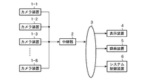
図1はこの発明の実施の形態1による映像監視システムの構成を示すブロック図である。この映像監視システムは、被写体を撮像して撮像画像をパケットにしてに配信するカメラ装置1−1,1−2,1−3,・・・,1−8、配信されたパケットを送受信する中継器2、ネットワーク3、ネットワーク3から配信される撮像画像を表示する表示装置4及びネットワーク3から配信される撮像画像を記録する録画装置5を備えている。
図1では8個のカメラ装置1−1,1−2,1−3,・・・,1−8が中継器2を介してネットワーク3に接続されているが、カメラ装置1の数はいくつでも良い。
また、図1において、カメラ装置1−1はマスタ動作を行い、カメラ装置1−2,1−3,・・・,1−8はスレーブ動作を行うように予め設定されているものとし、中継器2はIGMPスヌーピング機能を有していないものとする。
FIG. 1 is a block diagram showing a configuration of a video surveillance system according to
In FIG. 1, eight camera apparatuses 1-1, 1-2, 1-3,..., 1-8 are connected to the
In FIG. 1, the camera apparatus 1-1 is set in advance to perform a master operation, and the camera apparatuses 1-2, 1-3,..., 1-8 are set in advance to perform a slave operation. It is assumed that the
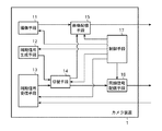
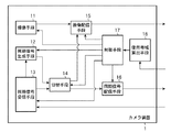
図2はこの発明の実施の形態1による各カメラ装置1の構成を示すブロック図である。このカメラ装置1は、撮像手段11、同期信号生成手段12、同期信号受信手段13、切替手段14、画像配信手段15、同期信号配信手段16及び制御手段17を備えている。
FIG. 2 is a block diagram showing the configuration of each
図2において、撮像手段11は制御手段17の指示により監視対象の被写体を撮像しデジタル化した撮像画像を出力する。同期信号生成手段12は、自機がマスタ動作を行う場合に、制御手段17の指示によりクロック信号等から撮像画像を一定間隔毎にネットワーク3に配信するタイミングを示す同期信号を生成する。同期信号受信手段13は、自機がスレーブ動作を行う場合に、制御手段17の指示によりマスタ動作を行うカメラ装置1から配信された同期信号を受信する。
In FIG. 2, the
切替手段14は、自機がマスタ動作を行う場合に、制御手段17の指示により、同期信号生成手段12により生成された同期信号を画像配信手段15及び同期信号配信手段16に出力し、自機がスレーブ動作を行う場合に、制御手段17の指示により同期信号受信手段13により受信された同期信号を画像配信手段15に出力する。画像配信手段15は、制御手段17の指示により、切替手段14により出力された同期信号に基づき、撮像手段11により出力された撮像画像をパケット化してネットワーク3に配信する。
The
同期信号配信手段16は、自機がマスタ動作を行う場合に、制御手段17の指示により、同期信号生成手段12により生成され切替手段14により出力された同期信号に基づき、ネットワーク3の使用帯域が一定になるように、スレーブ動作を行う各カメラ装置1から撮像画像をネットワーク3に配信するタイミングを示す同期信号を生成してスレーブ動作を行うカメラ装置1に配信する。制御手段17は、撮像手段11、同期信号生成手段12、同期信号受信手段13、切替手段14、画像配信手段15及び同期信号配信手段16を制御する。
When the own apparatus performs a master operation, the synchronization
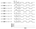
図3は各カメラ装置1からの撮像画像の配信タイミングとネットワーク3の使用帯域を説明する図である。図3では、カメラ装置1−1がマスタ動作し、その他のカメラ装置1−2〜1−8がスレーブ動作するものとし、カメラ装置1−1〜1−8を、カメラ装置1−1〜1−4とカメラ装置1−5〜1−8の二つのグループに分けて、撮像画像の配信タイミングを二つに分けている。すなわち、クロック信号20に対応して同期信号としての撮像画像の送出期間21と撮像画像の送出停止期間22を図3に示すタイミングにし、カメラ装置1−1〜1−4の撮像画像の配信期間21ではカメラ装置1−5〜1−8の撮像画像の配信停止期間22とし、カメラ装置1−1〜1−4の撮像画像の配信停止期間22ではカメラ装置1−5〜1−8の撮像画像の配信期間21とすることにより,ネットワーク3の使用帯域を時間tに対して常に一定にすることができる。
FIG. 3 is a diagram for explaining the distribution timing of the captured image from each
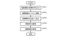
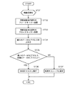
図4はマスタ動作を行うカメラ装置1−1の処理を示すフローチャートである。
ステップST11において、制御手段17は一定間間隔で例えば30ms毎に撮像画像の取得命令を撮像手段11へ送出する。
ステップST12において、撮像手段11は制御手段17からの取得命令により監視対象の被写体を撮像し光学系の入力信号をデジタル信号に変換し、変換した撮像画像を画像配信手段15に出力し、画像配信手段15は撮像手段11から出力された撮像画像を内部の蓄積デバイス等の例えばメモリ(図示せず)に格納する。
FIG. 4 is a flowchart showing processing of the camera device 1-1 that performs the master operation.
In step ST <b> 11, the
In step ST12, the
ステップST13において、同期信号生成手段12は制御手段17の指示によりクロック信号等から撮像画像を一定間隔毎にネットワーク3に配信するタイミングを示す同期信号を生成し、切替手段14は制御手段17の指示により同期信号生成手段12により生成された同期信号を画像配信手段15及び同期信号配信手段16に出力する。
In step ST <b> 13, the synchronization
ステップST14において、同期信号配信手段16は、制御手段17の指示により、同期信号生成手段12により生成され切替手段14により出力された同期信号に基づき、ネットワーク3の使用帯域が一定になるように、スレーブ動作を行う各カメラ装置1から撮像画像をネットワーク3に配信するタイミングを示す同期信号を生成してスレーブ動作を行うカメラ装置1に配信する。このとき、同期信号配信手段16は、スレーブ動作を行うカメラ装置1−2〜1−4に対しては、図3に示すように同期信号としての撮像画像の配信期間21と配信停止期間22をマスタ動作を行うカメラ装置1−1と同じ位相となるようにして配信し、スレーブ動作を行うカメラ装置1−5〜1−8に対しては、図3に示すように同期信号としての撮像画像の配信期間21と配信停止期間22をマスタ動作を行うカメラ装置1−1と反転した位相となるようにして配信する。
In step ST14, the synchronization signal distribution means 16 is based on the synchronization signal generated by the synchronization signal generation means 12 and output from the switching means 14 according to the instruction of the control means 17, so that the use band of the
ステップST15において、画像配信手段15は、制御手段17の指示により、同期信号生成手段12により生成され切替手段14により出力された同期信号に基づき、内部の蓄積デバイス等の例えばメモリに格納されている撮像画像をRTP(Real-time Transpoprt Protocol)フォーマットに従ってパケット化して中継器2を介してネットワーク3にマルチキャスト配信を行う。
表示装置4及び録画装置5はネットワーク3を介して配信される撮像画像を受信し、表示装置4は受信した撮像画像を表示し、録画装置5は受信した撮像画像を記録する。
In step ST15, the
The
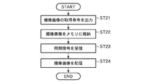
図5はスレーブ動作を行うカメラ装置1−2〜1−8の処理を示すフローチャートである。
ステップST21,ST22の処理は、図4に示すマスタ動作を行うカメラ装置1−1のステップST11,ST12の処理と同じである。
FIG. 5 is a flowchart showing processing of the camera devices 1-2 to 1-8 performing the slave operation.
The processes of steps ST21 and ST22 are the same as the processes of steps ST11 and ST12 of the camera device 1-1 that performs the master operation shown in FIG.
ステップST23において、同期信号受信手段13は制御手段17の指示によりマスタ動作を行うカメラ装置1から配信された同期信号を受信し、切替手段14は制御手段17の指示により同期信号受信手段13により受信された同期信号を画像配信手段15に出力する。
In step ST <b> 23, the synchronization
ステップST24において、画像配信手段15は、制御手段17の指示により、同期信号受信手段13により受信され切替手段14により出力された同期信号に基づき、内部の蓄積デバイス等の例えばメモリに格納されている撮像画像をRTPフォーマットに従ってパケット化して中継器2を介してネットワーク3にマルチキャスト配信を行う。
表示装置4及び録画装置5はネットワーク3を介して配信される撮像画像を受信し、表示装置4は受信した撮像画像を表示し、録画装置5は受信した撮像画像を記録する。
In step ST24, the image distribution means 15 is stored in, for example, a memory such as an internal storage device based on the synchronization signal received by the synchronization
The
図6は各カメラ装置1からの撮像画像の別の配信タイミングとネットワーク3の使用帯域を説明する図である。上記の説明では、カメラ装置1−1〜1−8は図3に示すタイミングで撮像画像を配信しているが、図6に示すように、各カメラ装置1からの撮像画像の配信開始タイミングを所定の時間ずらせるようにしても良い。
FIG. 6 is a diagram for explaining another distribution timing of the captured image from each
なお、この実施の形態1では、複数のカメラ装置1を二つのグループに分けて、撮像画像の配信タイミングを二つに分けているが、複数のカメラ装置1を二つ以上のグループに分けて、撮像画像の配信タイミングを二つ以上に分けても良い。
In the first embodiment, the plurality of
以上のように、この実施の形態1によれば、複数のカメラ装置1の撮像画像の配信タイミングを所定の数に分け、複数のカメラ装置1のうち、あるカメラ装置1が全体のカメラ装置1の配信タイミングを決定し、決定した配信タイミングに基づき撮像画像を配信するマスタ動作を行い、他のカメラ装置1がマスタ動作を行うカメラ装置1からの配信タイミングに基づき撮像画像を配信するスレーブ動作を行うことにより、IGMPスヌーピング機能を有する中継器やIPルータ等を必要とせずに安価なネットワーク構成で、しかもIGMP処理等のプロトコル処理を実装する必要がなく簡単なカメラ装置の構成で、ネットワークの使用帯域を一定に保つことができるという効果が得られる。
As described above, according to the first embodiment, the distribution timing of the captured images of the plurality of
実施の形態2.
上記実施の形態1では、各カメラ装置1はマスタ動作を行うか又はスレーブ動作を行うかが予め設定されているが、この実施の形態2は、カメラ装置1の起動時に所定のルールに基づき各カメラ装置1が自動的にマスタ動作を行うか又はスレーブ動作を行うかを設定するものである。
In the first embodiment, whether each
この発明の実施の形態2による映像監視システムの構成を示すブロック図は上記実施の形態1の図1と同一であり、各カメラ装置1の構成を示すブロック図は上記実施の形態1の図2と同一である。ただし、図2において、各カメラ装置1の制御手段17は互いに同期制御決定信号の送受信を行えるものとする。
The block diagram showing the configuration of the video surveillance system according to the second embodiment of the present invention is the same as FIG. 1 of the first embodiment, and the block diagram showing the configuration of each
図7は各カメラ装置1がマスタ動作を行うか又はスレーブ動作を行うかを設定する処理を示すフローチャートである。
ステップST31において、各カメラ装置1の制御手段17は機器初期化を行い、ステップST32において、各カメラ装置1の制御手段17はIP・MAC(Internet Protocol・Media Access Control)アドレスを含む同期制御決定信号を他のカメラ装置1にブロードキャスト送信を行う。
FIG. 7 is a flowchart showing processing for setting whether each
In step ST31, the
ステップST33において、各カメラ装置1の制御手段17は予め定められた所定時間内に他のカメラ装置1からブロードキャスト送信されたIP・MAC(Internet Protocol・Media Access Control)アドレスを含む同期制御決定信号を受信する。
ステップST34において、各カメラ装置1の制御手段17は、自機のIP・MACアドレスと受信した他のカメラ装置1のIP・MACアドレスの中で最小のIP・MACアドレスを求める。
In step ST33, the control means 17 of each
In step ST34, the control means 17 of each
ステップST35において、各カメラ装置1の制御手段17は、求めた最小のIP・MACアドレスが自機のIP・MACアドレスと一致するか否かをチェックする。
最小のIP・MACアドレスが自機のIP・MACアドレスと一致する場合には、ステップST36において、カメラ装置1の制御手段17は自機をマスター動作を行うカメラ装置1と設定し、最小のIP・MACアドレスが自機のIP・MACアドレスと一致しない場合には、ステップST37において、各カメラ装置1の制御手段17は自機をそれぞれスレーブ動作を行うカメラ装置1と設定する。
In step ST35, the control means 17 of each
If the minimum IP / MAC address matches the IP / MAC address of the own device, in step ST36, the control means 17 of the
マスタ動作を行うカメラ装置1の処理及びスレーブ動作を行うカメラ装置1の処理は、上記実施の形態1の図4及び図5に示す処理と同じであり、図4及び図5ではカメラ装置1−1がマスタ動作を行い、その他のカメラ装置1−2〜1−8がスレーブ動作を行っているが、この実施の形態2では、図7に示す処理により決定されたカメラ装置1がマスタ動作を行い、その他のカメラ装置1がスレーブ動作を行えば良い。
The processing of the
なお、この実施の形態2では、マスタ動作を行う機器を決定する所定のルールとして、最小のIP・MACアドレスを所有するカメラ装置1としたが、それ他のルールとして、例えば最大のIP・MACアドレスを所有するカメラ装置1や、予め定められたIP・MACアドレスを所有するカメラ装置1としても良い。
In the second embodiment, the
以上のように、この実施の形態2によれば、上記実施の形態1と同様の効果が得られると共に、カメラ装置1の起動時に、IP・MACアドレスに基づきマスタ動作を行うカメラ装置1とスレーブ動作を行うカメラ装置1を設定するようにしたので、予めマスタ動作を行うカメラ装置1とスレーブ動作を行うカメラ装置1を設定しておく必要がなくなるという効果が得られる。
As described above, according to the second embodiment, the same effects as those of the first embodiment can be obtained, and the
実施の形態3.
図8はこの発明の実施の形態3による映像監視システムの構成を示すブロック図である。この映像監視システムは、上記実施の形態1の図1にシステム制御装置6を追加したものであり、その他の構成は図1に示す構成と同一である。
この実施の形態2はマスタ動作を行っているカメラ装置1のトラブル発生時に強制的にマスタ動作を行うカメラ装置1を切り替えるものであり、システム制御装置6は、マスタ動作を行っているカメラ装置1のトラブル発生時に、トラブル発生したカメラ装置1にスレーブ設定コマンドを示すAPI(application program interface)コマンドを送信し、別のあるカメラ装置1にマスタ設定コマンドを示すAPIコマンドを送信する。
FIG. 8 is a block diagram showing a configuration of a video surveillance system according to
In the second embodiment, the
この発明の実施の形態3による各カメラ装置1の構成を示すブロック図は上記実施の形態1の図2と同一であるが、制御手段17はシステム制御装置6からのAPIコマンドを受信できるものとする。また、マスタ動作を行うカメラ装置1の処理及びスレーブ動作を行うカメラ装置1の処理は、上記実施の形態1の図4及び図5に示す処理と同じである。
The block diagram showing the configuration of each
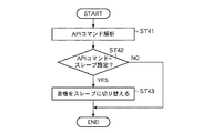
図9はマスタ動作を行っているカメラ装置1をスレーブ動作に切り替える処理を示すフローチャートである。
ステップST41において、マスタ動作を行いトラブルが発生したカメラ装置1の制御手段17は、システム制御装置6から送信されたAPIコマンドを受信して解析する。
FIG. 9 is a flowchart showing processing for switching the
In step ST41, the
ステップST42において、制御手段17は受信したAPIコマンドがスレーブ設定コマンドであるか否かをチェックする。
APIコマンドがスレーブ設定コマンドでなければ処理を終了し、APIコマンドがスレーブ設定コマンドである場合には、ステップST43において、制御手段17はマスタ動作を行うカメラ装置1からスレーブ動作を行うカメラ装置1に切り替える。
In step ST42, the control means 17 checks whether or not the received API command is a slave setting command.
If the API command is not a slave setting command, the process is terminated. If the API command is a slave setting command, in step ST43, the control means 17 changes from the
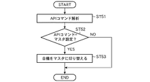
図10はスレーブ動作を行っているカメラ装置1をマスタ動作に切り替える処理を示すフローチャートである。
ステップST51において、スレーブ動作を行っているカメラ装置1の制御手段17は、システム制御装置6から送信されたAPIコマンドを受信して解析する。
FIG. 10 is a flowchart showing processing for switching the
In step ST51, the control means 17 of the
ステップST52において、制御手段17は受信したAPIコマンドがマスタ設定コマンドであるか否かをチェックする。
APIコマンドがマスタ設定コマンドでなければ処理を終了し、APIコマンドがマスタ設定コマンドである場合には、ステップST53において、制御手段17はスレーブ動作を行うカメラ装置1からマスタ動作を行うカメラ装置1に切り替える。
In step ST52, the control means 17 checks whether or not the received API command is a master setting command.
If the API command is not a master setting command, the process is terminated. If the API command is a master setting command, in step ST53, the control means 17 changes from the
新たにマスタ動作を行うよう設定されたカメラ装置1は上記実施の形態1の図4に示す処理を行い、新たにスレーブ動作を行うよう設定されたカメラ装置1は上記実施の形態1の図5に示す処理を行う。
The
以上のように、この実施の形態3によれば、上記実施の形態1と同様の効果が得られると共に、カメラ装置1の制御手段17がシステム制御装置6から送信されたAPIコマンドに基づき自機をマスタ動作を行うカメラ装置1又はスレーブ動作を行うカメラ装置1に切り替えることにより、マスタ動作を行っているカメラ装置1がトラブルを発生しても、撮像画像の配信を継続して行うことができるという効果が得られる。
As described above, according to the third embodiment, the same effects as those of the first embodiment can be obtained, and the
実施の形態4.
この実施の形態4は、ネットワーク3が混雑し、スレーブ動作を行っているカメラ装置1がマスタ動作を行っているカメラ装置1からの同期信号を受信できない可能性が生じたときに、自機で同期信号を生成して撮像画像を配信するものである。
In the fourth embodiment, when the
この発明の実施の形態4による映像監視システムの構成を示すブロック図は上記実施の形態1の図1と同一である。
図11はこの発明の実施の形態4による各カメラ装置1の構成を示すブロック図である。このカメラ装置1は、上記実施の形態1の図2に示すカメラ装置1に、カメラ装置1が接続されたネットワーク3の使用帯域を算出する使用帯域算出手段18を追加し、制御手段17の指示により、同期信号受信手段13により受信された同期信号を同期信号生成手段12に通知するようにしたもので、その他の構成は図2に示すものと同じである。
The block diagram showing the configuration of the video surveillance system according to the fourth embodiment of the present invention is the same as FIG. 1 of the first embodiment.
FIG. 11 is a block diagram showing the configuration of each
図12はネットワークが混雑したときのスレーブ動作を行っているカメラ装置1の処理を示すフローチャートである。
ステップST61において、スレーブ動作を行っているカメラ装置1の使用帯域算出手段18はネットワーク3のパケットを受信し、ステップST62において、使用帯域算出手段18は予め定めた単位時間当たりのパケット数を算出する。
FIG. 12 is a flowchart showing the processing of the
In step ST61, the used bandwidth calculating means 18 of the
ステップST63において、使用帯域算出手段18は算出した単位時間当たりのパケット数が所定の閾値未満か否か、すなわち、次の式(1)を満足するか否かをチェックしてチェック結果を制御手段17に通知する。
所定閾値>パケット数/単位時間 (1)
In step ST63, the used bandwidth calculating means 18 checks whether or not the calculated number of packets per unit time is less than a predetermined threshold, that is, whether or not the following expression (1) is satisfied, and the check result is controlled. 17 is notified.
Predetermined threshold value> number of packets / unit time (1)
使用帯域算出手段18から単位時間当たりのパケット数が所定の閾値未満でないという通知を受けた場合、すなわちネットワーク3が混雑している場合には、ステップST64において、制御手段17は、同期信号生成手段12に対して、同期信号受信手段13により受信された同期信号に基づき、同期信号を生成するように指示すると共に、切替手段14に対して同期信号生成手段12により生成された同期信号を同期配信手段15に出力するように指示する。
画像配信手段15は、制御手段17の指示により、同期信号生成手段12により生成され切替手段14により出力された同期信号に基づき、撮像手段11により出力された撮像画像をパケット化してネットワーク3に配信する。
When the notification that the number of packets per unit time is not less than the predetermined threshold is received from the use band calculation means 18, that is, when the
The
一方、使用帯域算出手段18から単位時間当たりのパケット数が所定の閾値未満であるという通知を受けた場合、すなわちネットワーク3が混雑していない場合には、ステップST65において、制御手段17は、同期信号受信手段14に対して引き続きマスタ動作を行っているカメラ装置1からの同期信号を受信するよう指示し、切替手段14に対して、引き続き同期信号受信手段13からの同期信号を同期配信手段15に出力するように指示する。
On the other hand, when the notification that the number of packets per unit time is less than the predetermined threshold is received from the use band calculation means 18, that is, when the
以上のように、この実施の形態4によれば、上記実施の形態1と同様の効果が得られると共に、ネットワークが混雑し、スレーブ動作を行っているカメラ装置1がマスタ動作を行っているカメラ装置1からの同期信号を受信できない可能性が生じたときに、自機で同期信号を生成することにより、ネットワーク3の負荷が高い状態で、マスタ動作を行っているカメラ装置1からの同期信号がパケットロスするような状態でも、撮像画像を配信することができるという効果が得られる。
As described above, according to the fourth embodiment, the same effects as those of the first embodiment can be obtained, and the
1,1−1,1−2,1−3,1−4,1−5,1−6,1−7,1−8 カメラ装置、2 中継器、3 ネットワーク、4 表示装置、5 録画装置、6 システム制御装置、11 撮像手段、12 同期信号生成手段、13 同期信号受信手段、14 切替手段、15 画像配信手段、16 同期信号配信手段、17 制御手段、18 使用帯域算出手段。 1,1-1,1-2,1-3,1-4,1-5,1-6,1-7,1-8 camera device, 2 repeater, 3 network, 4 display device, 5 recording device , 6 system control device, 11 imaging means, 12 synchronization signal generation means, 13 synchronization signal reception means, 14 switching means, 15 image distribution means, 16 synchronization signal distribution means, 17 control means, 18 use band calculation means.
Claims (10)
自機がマスタ動作を行う場合に撮像画像を一定間隔毎にネットワークに配信するタイミングを示す同期信号を生成する同期信号生成手段と、
自機がスレーブ動作を行う場合にマスタ動作を行うカメラ装置から配信された同期信号を受信する同期信号受信手段と、
自機がマスタ動作を行う場合に上記同期信号生成手段により生成された同期信号を出力し、自機がスレーブ動作を行う場合に上記同期信号受信手段により受信された同期信号を出力する切替手段と、
自機がマスタ動作を行う場合に、上記同期信号生成手段により生成され上記切替手段により出力された同期信号に基づき、上記ネットワークの使用帯域が一定になるように、スレーブ動作を行う各カメラ装置から撮像画像を上記ネットワークに配信するタイミングを示す同期信号を生成して配信する同期信号配信手段と、
上記切替手段により出力された同期信号に基づき、上記撮像手段により出力された撮像画像を上記ネットワークに配信する画像配信手段と、
上記撮像手段、上記同期信号生成手段、上記同期信号受信手段、上記切替手段、上記同期信号配信手段及び上記画像配信手段を制御する制御手段とを備えたカメラ装置。 Imaging means for imaging a subject to be monitored and outputting a captured image;
Synchronization signal generating means for generating a synchronization signal indicating the timing of delivering captured images to the network at regular intervals when the own device performs a master operation;
Synchronization signal receiving means for receiving a synchronization signal distributed from a camera device performing a master operation when the own device performs a slave operation;
Switching means for outputting the synchronization signal generated by the synchronization signal generating means when the own apparatus performs a master operation, and outputting the synchronization signal received by the synchronization signal receiving means when the own apparatus performs a slave operation; ,
When the own device performs the master operation, from each camera device that performs the slave operation so that the use band of the network is constant based on the synchronization signal generated by the synchronization signal generation unit and output by the switching unit. Synchronization signal distribution means for generating and distributing a synchronization signal indicating the timing of distributing the captured image to the network;
An image distribution unit that distributes the captured image output by the imaging unit to the network based on the synchronization signal output by the switching unit;
A camera apparatus comprising: the imaging unit; the synchronization signal generation unit; the synchronization signal reception unit; the switching unit; the synchronization signal distribution unit; and a control unit that controls the image distribution unit.
上記制御手段は、自機がスレーブ動作を行っている場合で、上記使用帯域算出手段により算出された上記ネットワークの使用帯域が混雑しているときに、上記同期信号生成手段に対して、上記同期信号受信手段により受信された同期信号に基づき、同期信号を生成するように指示すると共に、上記切替手段に対して上記同期信号生成手段により生成された同期信号を上記同期配信手段に出力するように指示することを特徴とする請求項1記載のカメラ装置。 A use band calculating means for calculating the use band of the network;
In the case where the control unit is performing a slave operation and the use band of the network calculated by the use band calculation unit is congested, the control unit sends the synchronization signal generation unit to the synchronization signal generation unit. Instructing to generate a synchronization signal based on the synchronization signal received by the signal reception means, and outputting the synchronization signal generated by the synchronization signal generation means to the synchronization distribution means to the switching means The camera device according to claim 1, wherein an instruction is given.
上記複数のカメラ装置のうち1つのカメラ装置が、各カメラ装置から上記ネットワークへの撮像画像の配信タイミングを、上記ネットワークの使用帯域が一定になるよう決定すると共に、決定した配信タイミングに基づき撮像画像を上記ネットワークに配信するマスタ動作を行い、
他のカメラ装置が、上記マスタ動作を行うカメラ装置により決定された配信タイミングに基づき、撮像画像を上記ネットワークに配信するスレーブ動作を行うことを特徴とする映像監視システム。 In a video surveillance system comprising a plurality of camera devices that capture a subject to be monitored and distribute the captured image to a network,
One camera device of the plurality of camera devices determines the distribution timing of the captured image from each camera device to the network so that the use band of the network is constant, and the captured image is based on the determined distribution timing. Perform master operation to distribute to the above network,
A video monitoring system, wherein another camera device performs a slave operation of distributing a captured image to the network based on a distribution timing determined by the camera device performing the master operation.
Priority Applications (1)
| Application Number | Priority Date | Filing Date | Title |
|---|---|---|---|
| JP2006016468A JP4704220B2 (en) | 2006-01-25 | 2006-01-25 | Camera device and video surveillance system |
Applications Claiming Priority (1)
| Application Number | Priority Date | Filing Date | Title |
|---|---|---|---|
| JP2006016468A JP4704220B2 (en) | 2006-01-25 | 2006-01-25 | Camera device and video surveillance system |
Publications (2)
| Publication Number | Publication Date |
|---|---|
| JP2007201701A true JP2007201701A (en) | 2007-08-09 |
| JP4704220B2 JP4704220B2 (en) | 2011-06-15 |
Family
ID=38455847
Family Applications (1)
| Application Number | Title | Priority Date | Filing Date |
|---|---|---|---|
| JP2006016468A Expired - Lifetime JP4704220B2 (en) | 2006-01-25 | 2006-01-25 | Camera device and video surveillance system |
Country Status (1)
| Country | Link |
|---|---|
| JP (1) | JP4704220B2 (en) |
Cited By (3)
| Publication number | Priority date | Publication date | Assignee | Title |
|---|---|---|---|---|
| JP2020084187A (en) * | 2018-11-19 | 2020-06-04 | 東レ株式会社 | Polyester film |
| CN114915754A (en) * | 2021-02-10 | 2022-08-16 | 丰田自动车株式会社 | Image processing system for vehicle, and image transmission method |
| WO2025203498A1 (en) * | 2024-03-28 | 2025-10-02 | Astemo株式会社 | Electronic control device |
Citations (6)
| Publication number | Priority date | Publication date | Assignee | Title |
|---|---|---|---|---|
| JPH0816943A (en) * | 1994-06-27 | 1996-01-19 | Atsumi Electron Corp Ltd | Monitor camera |
| JP2000316112A (en) * | 1999-04-30 | 2000-11-14 | Matsushita Electric Ind Co Ltd | Image signal switching method and apparatus, digital imaging camera and monitoring system using the same |
| JP2001245280A (en) * | 2000-02-29 | 2001-09-07 | Canon Inc | Camera control system, apparatus, method, and computer-readable storage medium |
| JP2003218935A (en) * | 2002-01-17 | 2003-07-31 | Matsushita Electric Ind Co Ltd | Unicast-multicast converter and video monitoring system |
| JP2004147262A (en) * | 2002-10-28 | 2004-05-20 | Matsushita Electric Ind Co Ltd | Network camera device and camera video distribution method |
| JP2005286453A (en) * | 2004-03-29 | 2005-10-13 | Hitachi Ltd | Surveillance camera and surveillance system |
-
2006
- 2006-01-25 JP JP2006016468A patent/JP4704220B2/en not_active Expired - Lifetime
Patent Citations (6)
| Publication number | Priority date | Publication date | Assignee | Title |
|---|---|---|---|---|
| JPH0816943A (en) * | 1994-06-27 | 1996-01-19 | Atsumi Electron Corp Ltd | Monitor camera |
| JP2000316112A (en) * | 1999-04-30 | 2000-11-14 | Matsushita Electric Ind Co Ltd | Image signal switching method and apparatus, digital imaging camera and monitoring system using the same |
| JP2001245280A (en) * | 2000-02-29 | 2001-09-07 | Canon Inc | Camera control system, apparatus, method, and computer-readable storage medium |
| JP2003218935A (en) * | 2002-01-17 | 2003-07-31 | Matsushita Electric Ind Co Ltd | Unicast-multicast converter and video monitoring system |
| JP2004147262A (en) * | 2002-10-28 | 2004-05-20 | Matsushita Electric Ind Co Ltd | Network camera device and camera video distribution method |
| JP2005286453A (en) * | 2004-03-29 | 2005-10-13 | Hitachi Ltd | Surveillance camera and surveillance system |
Cited By (6)
| Publication number | Priority date | Publication date | Assignee | Title |
|---|---|---|---|---|
| JP2020084187A (en) * | 2018-11-19 | 2020-06-04 | 東レ株式会社 | Polyester film |
| JP7532762B2 (en) | 2018-11-19 | 2024-08-14 | 東レ株式会社 | Polyester Film |
| CN114915754A (en) * | 2021-02-10 | 2022-08-16 | 丰田自动车株式会社 | Image processing system for vehicle, and image transmission method |
| JP2022122379A (en) * | 2021-02-10 | 2022-08-23 | トヨタ自動車株式会社 | Image processing system for vehicle, vehicle and image transmission method |
| JP7569010B2 (en) | 2021-02-10 | 2024-10-17 | トヨタ自動車株式会社 | Vehicle image processing system, vehicle, and image transmission method |
| WO2025203498A1 (en) * | 2024-03-28 | 2025-10-02 | Astemo株式会社 | Electronic control device |
Also Published As
| Publication number | Publication date |
|---|---|
| JP4704220B2 (en) | 2011-06-15 |
Similar Documents
| Publication | Publication Date | Title |
|---|---|---|
| CN100525152C (en) | Broadband digital broadcasting system and method | |
| CA2941430C (en) | Video transmission system and video receiver | |
| JP6098824B2 (en) | Camera system and switching device | |
| JP2012034343A (en) | Image processing apparatus and control method thereof | |
| JP4704220B2 (en) | Camera device and video surveillance system | |
| JP6609310B2 (en) | Method and apparatus for providing heterogeneous network-based broadcast service | |
| JP6188092B2 (en) | Information signal transmission / reception method via network, transmitter and receiver using the method, splitter unit for use in the network | |
| KR102275141B1 (en) | Apparatus and method for synchronizing multi-stream data received from multiple sub-controller in vehicle ethernet network | |
| JP6979092B2 (en) | Content output system and method | |
| JP2011176730A (en) | Content distribution apparatus and program, and content distribution system | |
| US10412441B2 (en) | Systems, methods, and devices for high-bandwidth digital content synchronization | |
| JP6383974B2 (en) | Playback system and playback method | |
| JP2020005063A (en) | Processing device and its control method, output device, synchronization control system, and program | |
| JP3839303B2 (en) | Transmission control device | |
| JP2010183237A (en) | System and method of content synchronous reproduction, reproduction terminal, method of controlling the same, and control program | |
| KR102093749B1 (en) | Content displaying system and method using multi-device base on web-browser | |
| US11038943B1 (en) | Content output system and method using multi-device base on web-browser | |
| JP6432067B2 (en) | Playback system and playback method | |
| JP2008131591A (en) | Lip sync control device and lip sync control method | |
| JP2021013134A (en) | Reception device, reception method, and transmission/reception system | |
| JP4624283B2 (en) | Relay client device, relay server device, and stream distribution system | |
| JP6469501B2 (en) | Video distribution system, video distribution method, and video distribution program | |
| JP2019211638A (en) | Processing device, output device, synchronization control system, and these control methods, as well as programs | |
| JP2008211694A (en) | Ip multicast distribution apparatus, content distribution system and ip multicast distribution method for use therein | |
| JP4327755B2 (en) | Digital broadcast signal switching transmission device |
Legal Events
| Date | Code | Title | Description |
|---|---|---|---|
| RD04 | Notification of resignation of power of attorney |
Free format text: JAPANESE INTERMEDIATE CODE: A7424 Effective date: 20071001 |
|
| RD04 | Notification of resignation of power of attorney |
Free format text: JAPANESE INTERMEDIATE CODE: A7424 Effective date: 20080626 |
|
| A621 | Written request for application examination |
Free format text: JAPANESE INTERMEDIATE CODE: A621 Effective date: 20080904 |
|
| A977 | Report on retrieval |
Free format text: JAPANESE INTERMEDIATE CODE: A971007 Effective date: 20101207 |
|
| A131 | Notification of reasons for refusal |
Free format text: JAPANESE INTERMEDIATE CODE: A131 Effective date: 20101214 |
|
| A521 | Request for written amendment filed |
Free format text: JAPANESE INTERMEDIATE CODE: A523 Effective date: 20110208 |
|
| TRDD | Decision of grant or rejection written | ||
| A01 | Written decision to grant a patent or to grant a registration (utility model) |
Free format text: JAPANESE INTERMEDIATE CODE: A01 Effective date: 20110301 |
|
| A61 | First payment of annual fees (during grant procedure) |
Free format text: JAPANESE INTERMEDIATE CODE: A61 Effective date: 20110309 |
|
| R150 | Certificate of patent or registration of utility model |
Ref document number: 4704220 Country of ref document: JP Free format text: JAPANESE INTERMEDIATE CODE: R150 |
|
| R250 | Receipt of annual fees |
Free format text: JAPANESE INTERMEDIATE CODE: R250 |
|
| R250 | Receipt of annual fees |
Free format text: JAPANESE INTERMEDIATE CODE: R250 |
|
| R250 | Receipt of annual fees |
Free format text: JAPANESE INTERMEDIATE CODE: R250 |
|
| R250 | Receipt of annual fees |
Free format text: JAPANESE INTERMEDIATE CODE: R250 |
|
| R250 | Receipt of annual fees |
Free format text: JAPANESE INTERMEDIATE CODE: R250 |
|
| R250 | Receipt of annual fees |
Free format text: JAPANESE INTERMEDIATE CODE: R250 |
|
| R250 | Receipt of annual fees |
Free format text: JAPANESE INTERMEDIATE CODE: R250 |
|
| R250 | Receipt of annual fees |
Free format text: JAPANESE INTERMEDIATE CODE: R250 |
|
| R250 | Receipt of annual fees |
Free format text: JAPANESE INTERMEDIATE CODE: R250 |
|
| R250 | Receipt of annual fees |
Free format text: JAPANESE INTERMEDIATE CODE: R250 |
|
| EXPY | Cancellation because of completion of term |