JP2007209651A - Therapeutic element passage display device - Google Patents
Therapeutic element passage display device Download PDFInfo
- Publication number
- JP2007209651A JP2007209651A JP2006034911A JP2006034911A JP2007209651A JP 2007209651 A JP2007209651 A JP 2007209651A JP 2006034911 A JP2006034911 A JP 2006034911A JP 2006034911 A JP2006034911 A JP 2006034911A JP 2007209651 A JP2007209651 A JP 2007209651A
- Authority
- JP
- Japan
- Prior art keywords
- plane
- tomographic
- point
- subject
- pixel value
- Prior art date
- Legal status (The legal status is an assumption and is not a legal conclusion. Google has not performed a legal analysis and makes no representation as to the accuracy of the status listed.)
- Withdrawn
Links
- 230000001225 therapeutic effect Effects 0.000 title claims abstract description 28
- 238000003780 insertion Methods 0.000 claims description 15
- 230000037431 insertion Effects 0.000 claims description 15
- 238000003384 imaging method Methods 0.000 claims description 11
- 238000004364 calculation method Methods 0.000 claims description 8
- 238000003860 storage Methods 0.000 claims description 5
- 238000013170 computed tomography imaging Methods 0.000 claims description 4
- 230000008014 freezing Effects 0.000 abstract description 56
- 238000007710 freezing Methods 0.000 abstract description 56
- 230000003902 lesion Effects 0.000 abstract description 37
- 230000017074 necrotic cell death Effects 0.000 abstract description 6
- 230000035515 penetration Effects 0.000 abstract description 4
- 238000012544 monitoring process Methods 0.000 description 35
- 238000000034 method Methods 0.000 description 30
- 239000007789 gas Substances 0.000 description 26
- 238000010257 thawing Methods 0.000 description 19
- 238000012545 processing Methods 0.000 description 15
- XKRFYHLGVUSROY-UHFFFAOYSA-N Argon Chemical compound [Ar] XKRFYHLGVUSROY-UHFFFAOYSA-N 0.000 description 10
- 230000008859 change Effects 0.000 description 10
- 238000010586 diagram Methods 0.000 description 9
- 210000004204 blood vessel Anatomy 0.000 description 7
- 206010028980 Neoplasm Diseases 0.000 description 6
- 201000011510 cancer Diseases 0.000 description 6
- 238000000315 cryotherapy Methods 0.000 description 6
- 206010058467 Lung neoplasm malignant Diseases 0.000 description 5
- 206010028851 Necrosis Diseases 0.000 description 5
- 229910052786 argon Inorganic materials 0.000 description 5
- 239000001307 helium Substances 0.000 description 5
- 229910052734 helium Inorganic materials 0.000 description 5
- SWQJXJOGLNCZEY-UHFFFAOYSA-N helium atom Chemical compound [He] SWQJXJOGLNCZEY-UHFFFAOYSA-N 0.000 description 5
- 201000005202 lung cancer Diseases 0.000 description 5
- 208000020816 lung neoplasm Diseases 0.000 description 5
- 238000005259 measurement Methods 0.000 description 4
- 239000002184 metal Substances 0.000 description 4
- 229910052751 metal Inorganic materials 0.000 description 4
- 230000008569 process Effects 0.000 description 4
- 238000009826 distribution Methods 0.000 description 3
- 229940079593 drug Drugs 0.000 description 3
- 239000003814 drug Substances 0.000 description 3
- 230000033001 locomotion Effects 0.000 description 3
- 210000001519 tissue Anatomy 0.000 description 3
- 230000009471 action Effects 0.000 description 2
- 230000036760 body temperature Effects 0.000 description 2
- 210000000988 bone and bone Anatomy 0.000 description 2
- 238000012790 confirmation Methods 0.000 description 2
- 230000000694 effects Effects 0.000 description 2
- 238000002594 fluoroscopy Methods 0.000 description 2
- 230000009545 invasion Effects 0.000 description 2
- 210000004072 lung Anatomy 0.000 description 2
- 239000011159 matrix material Substances 0.000 description 2
- 230000007246 mechanism Effects 0.000 description 2
- 239000013307 optical fiber Substances 0.000 description 2
- 238000004088 simulation Methods 0.000 description 2
- 230000002123 temporal effect Effects 0.000 description 2
- 238000003325 tomography Methods 0.000 description 2
- 238000010521 absorption reaction Methods 0.000 description 1
- 230000008901 benefit Effects 0.000 description 1
- 230000030833 cell death Effects 0.000 description 1
- 238000005520 cutting process Methods 0.000 description 1
- 230000006837 decompression Effects 0.000 description 1
- 238000011156 evaluation Methods 0.000 description 1
- 230000006870 function Effects 0.000 description 1
- 230000002496 gastric effect Effects 0.000 description 1
- 210000002216 heart Anatomy 0.000 description 1
- 230000020169 heat generation Effects 0.000 description 1
- 238000002347 injection Methods 0.000 description 1
- 239000007924 injection Substances 0.000 description 1
- 238000007689 inspection Methods 0.000 description 1
- 230000001678 irradiating effect Effects 0.000 description 1
- 239000000463 material Substances 0.000 description 1
- 210000000056 organ Anatomy 0.000 description 1
- 210000000496 pancreas Anatomy 0.000 description 1
- 230000000704 physical effect Effects 0.000 description 1
- 238000002360 preparation method Methods 0.000 description 1
- 210000002307 prostate Anatomy 0.000 description 1
- 150000003839 salts Chemical class 0.000 description 1
- 239000007787 solid Substances 0.000 description 1
- 229910001220 stainless steel Inorganic materials 0.000 description 1
- 239000010935 stainless steel Substances 0.000 description 1
- 238000012360 testing method Methods 0.000 description 1
- 238000002560 therapeutic procedure Methods 0.000 description 1
Images
Landscapes
- Apparatus For Radiation Diagnosis (AREA)
- Thermotherapy And Cooling Therapy Devices (AREA)
Abstract
Description
本発明は、被検体内の穿刺して治療等を行う治療子の経路表示装置に関する。 The present invention relates to a path display device for a treatment child that performs puncture in a subject to perform treatment or the like.
医療装置の中には、被検体の体内に侵入具(治療子)を侵入(穿刺を含む)させる装置がある。例えば胃カメラ、監視用光ファイバー、組織を切り取って採取する採取具、特定の部位に薬剤を注入する注入具、病巣部位に熱や電磁波などのエネルギーを照射して治療を行う治療具などがある。
こうした侵入具の侵入監視用に透視像をリアルタイムで得て表示して侵入を監視する透視監視法、X線CT断層像をリアルタイムで得て二次元又は三次元表示させて侵入を監視するCT監視法がある。
こうした透視監視法、CT監視法は、術者が画面を見ながら監視し、この監視画像から術者が位置やルートを決定確認しながら、医療を施すやり方をとる。
CT監視法とは、侵入経路及び患部をCT撮影しながらリアルタイムでCT画像及び又はその三次元化した画像を表示させ、この表示画面を術者が監視しながら侵入具の進行及び治療を行う治療法を指す。CT監視法は、複雑な部位や身体の深化した部位(肺や心臓、前立腺や膵臓等)での監視に向いている。このCT監視法を使用した最新例として、肺癌組織の壊死をはかる凍結治療法がある。この凍結療法とは、肺癌部位細胞を凍結させ、その後で融解させ、その融解の過程で塩濃度の差の発生等により細胞内を破壊し、細胞死に至らしめるという原理による。凍結と融解には、2つの高圧ガスを使う。高圧のガスは急激に体積を膨張させると、分子の種類により急激に温度を上げるものと、急激に温度を下げるものとがあり、これは物理現学の1つであるJoule-Thompson効果と呼ばれる。そこで、温度を揚げる方に高圧アルゴンガスを、温度を下げる方にヘリウムガスを使用する。治療には、侵入具として中空の金属性の治療子(治療具と同義。ガイドニードルとも呼ばれる)を用いる。CT監視下で、この治療子を患部まで誘導し、上記2つのガスを交互に中空内から又は中空部の先端から外部へ放出し、熱交換作用を利用して患部への凍結療法を行う。
Among medical devices, there is a device that allows an intruder (therapeutic child) to enter (including puncture) into the body of a subject. For example, there are a gastric camera, a monitoring optical fiber, a collection tool for cutting and collecting a tissue, an injection tool for injecting a drug into a specific site, and a treatment tool for treating a lesion site by irradiating energy such as heat or electromagnetic waves.
For intrusion monitoring of such an intruder, a fluoroscopic monitoring method in which a fluoroscopic image is obtained and displayed in real time to monitor the intrusion, and CT monitoring in which an X-ray CT tomographic image is obtained in real time and displayed in two or three dimensions to monitor the invasion. There is a law.
Such fluoroscopy monitoring method and CT monitoring method are a method in which an operator performs monitoring while looking at a screen, and an operator performs medical treatment while determining and confirming the position and route from the monitoring image.
The CT monitoring method is a treatment in which a CT image and / or a three-dimensional image thereof are displayed in real time while performing CT imaging of an intrusion route and an affected part, and an operator advances and treats the intruder while monitoring the display screen. Refers to the law. The CT monitoring method is suitable for monitoring a complex part or a deepened part of the body (lung, heart, prostate, pancreas, etc.). The latest example using this CT monitoring method is a cryotherapy method for necrosis of lung cancer tissue. This cryotherapy is based on the principle that the lung cancer site cells are frozen and then thawed, and the inside of the cells is destroyed by the generation of a difference in salt concentration in the process of thawing, leading to cell death. Two high-pressure gases are used for freezing and thawing. When the volume of high-pressure gas expands suddenly, there are ones that rapidly increase the temperature depending on the type of molecule, and ones that rapidly decrease the temperature. This is called the Joule-Thompson effect, which is one of the physical phenomena. . Therefore, high-pressure argon gas is used to raise the temperature, and helium gas is used to lower the temperature. For treatment, a hollow metallic treatment piece (synonymous with treatment tool, also called a guide needle) is used as an intrusion tool. Under CT monitoring, this therapeutic child is guided to the affected part, and the two gases are alternately discharged from the inside of the hollow or the tip of the hollow part to the outside, and cryotherapy is performed on the affected part using the heat exchange action.
こうした一般的な凍結療法の文献として、非特許文献1がある。更に、凍結療法に用いる治療子を含む機械系、及びその治療のやり方と実際事例とを解説した文献として、非特許文献2がある。
文献2は、治療子の穿刺状態を、リアルタイムでX線CT装置で撮影してこれをリアルタイムで断層画像として再構成して表示させ、手技を行うとしたものである。X線CT装置は、マルチスライス撮影であり、一回で多数の断層像を得て表示させる。治療子の進行を監視でき、患部位置への追跡、手技に沿ってほぼリアルタイムで画像としてみることができる。
一方、治療子は、先端が刃物状に突起するステンレス製の二重管(コアキシャルニードル)を使う。治療に当っては、この二重管を体表面にあてがった状態で、二重管の中心軸に沿って長く細い誘導針を挿入し、その誘導針を患部まで穿刺する。次にその誘導針に沿って二重管を患部まで進行させ、更に二重管を進めて腫瘍を貫通させる。 On the other hand, the treatment element uses a stainless steel double tube (coaxial needle) whose tip protrudes like a blade. In the treatment, with the double tube placed on the body surface, a long and thin guide needle is inserted along the central axis of the double tube, and the guide needle is punctured to the affected area. Next, the double tube is advanced to the affected area along the guide needle, and the double tube is further advanced to penetrate the tumor.
この後で上記誘導針を抜いて、代りに凍結端子本体を二重管内の中空の軸に沿って挿通装填する。この際凍結端子本体の凍結・解凍部位となる端子先端は、二重管の先端のまるみを帯びた内面に当接又は近接した位置とする。凍結端子本体は高圧アルゴンガス注入口と高圧ヘリウムガス注入口へと切替バルブを介してつながる。充填確認後に切替バルブを切替えて高圧ヘリウムガスを注入し、次いで高圧アルゴンガスを注入し、凍結と解凍とを短時間で実行する。このサイクルを複数回繰返すこともある。これらの一連の動作はリアルタイムでのCT画像を表示させてのCT監視下で、観察確認しながら行う。 Thereafter, the guide needle is removed, and the frozen terminal main body is inserted and loaded along the hollow shaft in the double tube instead. At this time, the terminal tip that becomes the freezing and thawing part of the frozen terminal body is in a position in contact with or close to the rounded inner surface of the tip of the double tube. The freezing terminal body is connected to a high-pressure argon gas inlet and a high-pressure helium gas inlet via a switching valve. After the filling is confirmed, the switching valve is switched to inject high-pressure helium gas, then high-pressure argon gas is injected, and freezing and thawing are performed in a short time. This cycle may be repeated multiple times. A series of these operations are performed while observing and confirming under CT monitoring with displaying a real-time CT image.
凍結端子を含む治療子は事前に定めたルート(経路)に従って行ったり、患部を開いて観察できる状態にしたりして、穿刺を行う。
経路は、侵入点と目標病巣位置(到達点)とを定めた上で決定する。しかし、経路状に血管や他の臓器や骨などの障害物がないことを確認するのは容易ではない。この確認をCT画像や透視像をもとにして行う例もある。
侵入点と到達点とを結ぶ経路を画像上で正確に確認できれば、治療効率につながり、操作者の負担も軽くなる。
The treatment child including the freezing terminal is punctured in accordance with a predetermined route (path) or opened so that the affected part can be observed.
The route is determined after defining the entry point and the target lesion position (arrival point). However, it is not easy to confirm that there are no obstacles such as blood vessels, other organs, and bones in the path. There is an example in which this confirmation is performed based on a CT image or a fluoroscopic image.
If the route connecting the entry point and the arrival point can be accurately confirmed on the image, the treatment efficiency is improved and the burden on the operator is reduced.
本発明の目的は、侵入点と到達点とを結ぶ経路を断層画像上に正確に表示可能な表示装置を提供するものである。 An object of the present invention is to provide a display device capable of accurately displaying a path connecting an entry point and a reaching point on a tomographic image.
更に本発明の目的は、そのために計測で求めたものでない、経路の判断しやすい新たな断層面と断層像を算出し表示可能とする表示装置を提供するものである。 Further, an object of the present invention is to provide a display device that can calculate and display a new tomographic plane and a tomographic image that are not obtained by measurement and are easy to determine the path.
本発明は、被検体の撮影で得た断層像を断層平面と直交する方向に重ねて得られる三次元画像データを格納する格納手段と、
上記三次元画像における被検体侵入具の侵入点と被検体内到達点とを設定する手段と、
この侵入点と到達点を通る第1平面、及びこの侵入点と到達点とを通り上記第1平面に所定角度をなす第2平面を設定する手段と、
第1平面と上記三次元画像データの各断層面との交点の画素値、又は交点近傍の画素値から近似した画素値を、第1平面の交点の画素値として決定し、かくして第1平面の断層画像データを算出する第1の算出手段と、
第2平面と上記三次元画像データの各断層面との交点の画素値、又は交点近傍の画素値から近似した新画素値を、第2平面の交点の画素値として決定し、かくして第2平面の断層画像データを算出する第2の算出手段と、
上記算出した第1平面の断層像、第2平面の断層像を表示する表示手段と、
を備える治療子経路表示装置を開示する。
The present invention comprises a storage means for storing three-dimensional image data obtained by superimposing tomographic images obtained by imaging a subject in a direction perpendicular to the tomographic plane;
Means for setting the entry point of the subject entry tool and the in-subject arrival point in the three-dimensional image;
Means for setting a first plane passing through the entry point and the arrival point, and a second plane passing through the entry point and the arrival point and forming a predetermined angle with the first plane;
A pixel value approximated from a pixel value at an intersection of the first plane and each tomographic plane of the three-dimensional image data or a pixel value in the vicinity of the intersection is determined as a pixel value at the intersection of the first plane, and thus the first plane First calculation means for calculating tomographic image data;
The pixel value at the intersection of the second plane and each tomographic plane of the 3D image data or a new pixel value approximated from the pixel value near the intersection is determined as the pixel value at the intersection of the second plane, and thus the second plane Second calculating means for calculating the tomographic image data of
Display means for displaying the calculated tomographic image of the first plane and the tomographic image of the second plane;
A therapeutic element route display device comprising:
更に本発明は、前記所定角度は90°とする治療子経路表示装置を開示する。 Furthermore, the present invention discloses a treatment element path display device in which the predetermined angle is 90 °.
更に本発明は、前記格納手段は、侵入具の進行時の先端位置をCT撮影・再構成して得た先端位置近傍の複数の断層像を含むものとした治療子経路表示装置を開示する。 Furthermore, the present invention discloses a treatment element path display device in which the storage means includes a plurality of tomographic images in the vicinity of the distal end position obtained by CT imaging / reconstruction of the distal end position during the advancement of the intruder.
更に本発明は、被検体の撮影で得られた断層像を断層像平面と直交する方向に重ねて得られる3次元画像データを求め、被検体侵入具の侵入点と到達点とを同一平面内に持つ様に定めた画像表示装置を開示する。 Furthermore, the present invention obtains three-dimensional image data obtained by superimposing tomographic images obtained by imaging a subject in a direction orthogonal to the tomographic image plane, and sets the entry point and the arrival point of the subject entry tool within the same plane. An image display device defined to be included is disclosed.
更に本発明は、被検体の撮影で得られた断層像を断層像平面と直交する方向に重ねて得られる3次元画像データを求め、被検体侵入具の侵入点と到達点とを同一平面内に持つように定めた画像と侵入具の侵入点と到達点とを結ぷ直線を軸として回転して得られる他の画像の2つ以上を表示することの出来る画像表示装置を開示する。 Furthermore, the present invention obtains three-dimensional image data obtained by superimposing tomographic images obtained by imaging a subject in a direction orthogonal to the tomographic image plane, and sets the entry point and the arrival point of the subject entry tool within the same plane. An image display apparatus capable of displaying two or more other images obtained by rotating an image determined to have an intrusion point and an arrival point of an intruder and rotating about a straight line is disclosed.
更に本発明は、被検体の撮影で得られた断層像を断層平面と直交する方向に重ねて得られる3次元画像データを求め被検体侵入具侵入点と到達点とを結んで得られる直線の3次元画像データとの角度を持った侵入具挿入装置を開示する。 Furthermore, the present invention obtains three-dimensional image data obtained by superimposing tomographic images obtained by imaging a subject in a direction orthogonal to the tomographic plane, and obtains a straight line obtained by connecting the object intruder entry point and the arrival point. An intruder insertion device having an angle with three-dimensional image data is disclosed.
本発明の表示装置によれば、侵入点と到達点とを結ぶ2つの経路平面の断層像を観察でき、経路の確認や治療子の侵入の様子がわかるようになった。 According to the display device of the present invention, it is possible to observe the tomographic images of the two path planes connecting the entry point and the arrival point, and to confirm the path and the state of the treatment element intrusion.
本発明を治療子の穿刺経路表示装置の例で説明する。治療子とは、患者の体内に穿刺して病巣部位の治療を行う素子である。例えば肺癌の除去手段として凍結端子本体を内部に有する金属管から成る治療子を使う例がある。かかる治療子は、肺癌病巣部位まで凍結端子を穿刺して、病巣部位に到達後に、凍結端子本体の先端からその周囲に対して凍結と解凍とを繰返して病巣部位を壊死させるものである。
かかる凍結端子、及び凍結端子を含む広義の治療子を使う治療装置に関して、本件出願人は既に特許出願を行っている(特願2005−364654、特願2005−364659)。
The present invention will be described with reference to an example of a puncture route display device for a treatment child. A therapeutic element is an element that punctures a patient's body and treats a lesion site. For example, as a means for removing lung cancer, there is an example in which a therapeutic element made of a metal tube having a freezing terminal body inside is used. In this treatment child, a freezing terminal is punctured to a lung cancer lesion site, and after reaching the lesion site, freezing and thawing are repeated from the tip of the freezing terminal body to its surroundings to necrotize the lesion site.
The applicant has already filed a patent application regarding such a freezing terminal and a therapeutic device using a therapeutic device in a broad sense including the freezing terminal (Japanese Patent Application Nos. 2005-364654 and 2005-364659).
凍結端子を含む治療子の穿刺を行うためには、侵入点としての体内への穿刺入口位置と到達点としての病巣部位到達位置とを特定した上でその両者を結ぶ穿刺経路を決定し、この経路に沿うような挿入角度を与えて、その経路に沿うように治療子の穿刺を行う。
入口位置から病巣部位位置までの治療子の進行は、CT監視下で行う。CT監視とは、治療子の存在位置を含むCT断層像をリアルタイムで計測・再構成を行って表示させるものであり、治療子の侵入位置に併せて次々に断層像を得て表示させ、治療子が事前に決定した経路を進んでいるかを監視するものである。
In order to puncture a treatment element including a freezing terminal, a puncture route that connects the puncture entrance position to the body as an entry point and a lesion site arrival position as an arrival point is determined, and this is determined. An insertion angle along the path is given, and the therapeutic element is punctured along the path.
The progress of the treatment child from the entrance position to the lesion site position is performed under CT monitoring. CT monitoring is to measure and reconstruct a CT tomogram including the location of the treatment element in real time and display it. It monitors whether the child is following a predetermined route.
本発明は、かかるCT監視を行うに際して、通常のCT断層像を表示させると共に、侵入点P1と病巣目標位置即ち到達点P2とを含む新たな2つの平面Q1、Q2を設定し、この2つの平面Q1、Q2上の全画素値を、上記通常の断層像の画素値から算出する。かくして、断層面Q1、Q2での断層画像データR1、R2を得る。これを画面に表示する。画面上にはP1、P2点が明示的に表示する。平面Q1、Q2とは例えば平面間の角度βが90°(直交)である。従って、平面Q1の断層像によってQ1平面上で、治療子がP1→P2への経路をたどっているかを監視できると共に、それに直交する平面Q2上で、P1→P2への経路をたどっているかを監視できることになる。
これによって、1つの平面Q1だけではその平面上での動きだけの監視のみであるのに対し、本発明では、互いに直交する平面Q1とQ2とで立体的に動きを監視することができる。
The present invention displays a normal CT tomographic image when performing such CT monitoring, and sets two new planes Q1 and Q2 including an intrusion point P1 and a lesion target position, that is, an arrival point P2. All pixel values on the planes Q1 and Q2 are calculated from the pixel values of the normal tomographic image. Thus, tomographic image data R1 and R2 at the tomographic planes Q1 and Q2 are obtained. This is displayed on the screen. P 1 and P 2 points are explicitly displayed on the screen. For example, the angle β between the planes Q1 and Q2 is 90 ° (orthogonal). Therefore, it is possible to monitor whether the therapeutic element follows the path from P1 to P2 on the Q1 plane by the tomographic image of the plane Q1, and whether to follow the path from P1 to P2 on the plane Q2 orthogonal thereto. You can monitor it.
As a result, only the movement on the plane can be monitored with only one plane Q1, whereas in the present invention, the movement can be monitored three-dimensionally with the planes Q1 and Q2 orthogonal to each other.
以下、図面を利用して具体的に説明する。
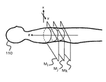
図1は、被検体110と断層面と座標系X−Y−Zとの関係を示す図である。断層面は体軸方向に複数個有し、図では模式的に、i、j、kの3断層面を示している。断層面そのものはX−Y座標系とし、体軸方向をZ座標系として、被検体の任意の点は、(X,Y,Z)の座標系で定義できる。断層面の体軸方向でのピッチは、1mm以下、例えば100分の1mmとかである。断層面の画像はCT計測で得たCT画像であり、またピッチを細かくするために補間によって新断層面のCT画像を得る例もある。
Hereinafter, it demonstrates concretely using drawing.
FIG. 1 is a diagram showing the relationship among the subject 110, the tomographic plane, and the coordinate system XYZ. A plurality of tomographic planes are provided in the body axis direction, and three tomographic planes i, j, and k are schematically shown in the drawing. The tomographic plane itself can be defined as an XY coordinate system, the body axis direction can be defined as a Z coordinate system, and any point of the subject can be defined by a coordinate system of (X, Y, Z). The pitch of the tomographic plane in the body axis direction is 1 mm or less, for example, 1/100 mm. The tomographic image is a CT image obtained by CT measurement, and there is also an example in which a CT image of a new tomographic surface is obtained by interpolation in order to make the pitch fine.
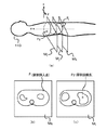
図2(a)は、治療子の挿入点P1、及び目標点(到達点)P2を示した図である。新断層面MkのP1点を挿入点、断層面MiのP2点を到達点と指定した例を示す。図2(b)が断層面Mkの断層画像上の挿入点P1、図2(c)が断層面Miの断層画像上の到達点P2であり、P1点は被検体の外皮位置、P2点は被検体の内部病巣位置に設定した。
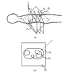
図3(a)は、点P1,P2を新断層面Q1の設定例を示す。当然の事ながら、新断層面Q1は本来のCT断層面(…Mi、…Mj、…Mk、…)と非平行である。図3(b)は、新断層面Q1上での算出画素値から成る新断層像例を示す。ここで、算出画素値とは、新平面Q1でのものであることから、計測したCT断層面(…Mi、…Mj、…Mk、…)の画素値から算出して得たものである。この算出の意味については後述する。
FIG. 2A is a diagram showing an insertion point P1 and a target point (arrival point) P2 of the treatment child. An example in which the P1 point of the new tomographic plane Mk is designated as the insertion point and the P2 point of the tomographic plane Mi is designated as the reaching point is shown. 2B is the insertion point P1 on the tomographic image of the tomographic plane Mk, FIG. 2C is the arrival point P2 on the tomographic image of the tomographic plane Mi, the P1 point is the outer skin position of the subject, and the P2 point is Set to the location of the internal lesion of the subject.
FIG. 3A shows an example of setting the new tomographic plane Q1 at points P1 and P2. As a matter of course, the new fault plane Q1 is not parallel to the original CT fault plane (... Mi, ... Mj, ... Mk, ...). FIG. 3B shows an example of a new tomographic image composed of calculated pixel values on the new tomographic plane Q1. Here, since the calculated pixel value is in the new plane Q1, it is obtained by calculating from the pixel value of the measured CT tomographic plane (... Mi,... Mj,... Mk,...). The meaning of this calculation will be described later.
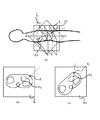
図4(a)は、新平面Q1と所定の角度βをなす新平面Q2の設定例を示す。新平面Q2は平面Q1と同じく点P1とP2とを通る平面であり、角度βは、例えば90°(直交)である。図4(b)は、平面Q1の新断層像、図4(c)は平面Q2の新断層像であり、いずれも算出された画素値より成る。
かかるP1とP2とを通る互いに角度βをなす2つの新平面Q1とQ2との新断層像を表示することで、P1とP2との経路がどんなものであるか、その途中に障害物があるかがわかることになり、P1、P2の評価が可能となる。また、治療子の挿入角度θの設定及び評価が可能となる。そして、もし、更に別のP1、P2、θの設定が良いと判断されれば、別個にP1、P2、θを設定し直し、同様の表示を行って評価をすればよい。
FIG. 4A shows a setting example of a new plane Q2 that forms a predetermined angle β with the new plane Q1. The new plane Q2 is a plane that passes through the points P1 and P2 like the plane Q1, and the angle β is, for example, 90 ° (orthogonal). 4B is a new tomographic image of the plane Q1, and FIG. 4C is a new tomographic image of the plane Q2, both of which are calculated pixel values.
By displaying new tomographic images of two new planes Q1 and Q2 passing through P1 and P2 and having an angle β with each other, what is the path between P1 and P2 and an obstacle in the middle As a result, it is possible to evaluate P1 and P2. In addition, it is possible to set and evaluate the insertion angle θ of the therapeutic element. If it is determined that another setting of P1, P2, and θ is good, P1, P2, and θ may be reset separately, and the same display may be performed for evaluation.
次に、平面Q1とQ2との設定を説明する。
Q1とQ2とが互いに直交する平面であるとすると、平面Q1を定めると、平面Q2は1つしかなく一義的に定まる。然るに平面Q1はP1とP2とを含む平面であり無数に存在する。そこで、事前に、穿刺経路上にあって侵入の障害物(例えば血管とか骨とか)がなく、経路監視のしやすい平面Q1候補がいくつか存在する。一方、これらの各平面Q1候補についてそれぞれに直交する平面Q2候補が定まる。平面Q2候補にあっても障害物が経路上にないことが必要である。こうしたQ1とQ2の各候補の中で、障害物がなく、監視しやすい経路を有する平面をQ1、Q2として決定する。これらの決定法は、術者によって画面を見ながら行うが、ソフトウェアによって行うやり方もある。
Next, the setting of the planes Q1 and Q2 will be described.
Assuming that Q1 and Q2 are planes orthogonal to each other, when the plane Q1 is defined, there is only one plane Q2 and it is uniquely determined. However, the plane Q1 is a plane including P1 and P2, and there are countless numbers. Therefore, in advance, there are several plane Q1 candidates that are on the puncture route, have no intrusion obstacles (for example, blood vessels or bones), and are easy to monitor the route. On the other hand, a plane Q2 candidate that is orthogonal to each of these plane Q1 candidates is determined. Even in the plane Q2 candidate, it is necessary that the obstacle is not on the route. Among these candidates for Q1 and Q2, planes having no obstacles and easy to monitor are determined as Q1 and Q2. These determination methods are performed while looking at the screen by an operator, but there are also methods performed by software.
平面Q1とQ2とは直交させない例もある。例えば適切な直交平面Q2が見いだせなかった場合には、直交平面以外の平面Q2を選ぶ必要がある。また、直交平面以外の角度の平面Q2が経路監視に適した例もある。こうした場合も、平面Q1に対応する所定の回転角度β(≠90°)の関係にある平面Q2を事前に決定しておく。例えばβ=60°の事例では、Q1に対して4個の60°平面Q2があり、どれかに特定する。 In some cases, the planes Q1 and Q2 are not orthogonal to each other. For example, when an appropriate orthogonal plane Q2 cannot be found, it is necessary to select a plane Q2 other than the orthogonal plane. There is also an example in which the plane Q2 having an angle other than the orthogonal plane is suitable for route monitoring. Also in such a case, the plane Q2 having a relationship of a predetermined rotation angle β (≠ 90 °) corresponding to the plane Q1 is determined in advance. For example, in the case of β = 60 °, there are four 60 ° planes Q2 with respect to Q1, and one of them is specified.
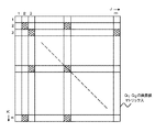
平面Q1とQ2上での新画素値の算出を図5で説明する。平面Q1はm×nの画素数のマトリックス構成である。この画素値算出は、ソフトウェアによって自動的に行う。平面Q1とCT断層面との角度は90°以外の角度αである。穿刺入口P1が皮膚表面であって病巣位置P2が内部である故にP1とP2とを結ぶ平面Q1は、CT平面に対して90°以外の角度になるからである。
平面Q1上の画素位置を(J,K)とし、CT断層平面の画素位置を(X,Y)とし、CT断層面の体軸方向の座標をZとする。CT断層面を手前からM1、M2、…Mnとする。こうしたCT断層面M1、M2、…Mnが並んであり、これに角度αで平面Q1がCT断層面M1、M2、…Mnを切断(角度αでの交叉)するような関係である。
そこで、その全交叉位置での、Q1平面の座標(J,K)とそれに交叉するCT断層面M1、M2、…Mnの座標(X,Y)に、図5の斜線画素位置の如き、画素値があれば、それをQ1平面の対応座標の画素値とする。座標(X,Y)に、図5の非斜線画素位置の如き、画素値がない場合が多く、この場合には座標(X,Y)の周囲2点とか4点とかの画素値から近似算出した近似画素値を座標(J,K)の画素値とする。この算出は、平均値とするとか、距離差を考慮した比例配分値とするとかである。算出しないで、最も違い位置の画素値をそのまま利用する例もある。
平面Q2についても同様である。
Calculation of new pixel values on the planes Q1 and Q2 will be described with reference to FIG. The plane Q1 has a matrix configuration of m × n pixels. This pixel value calculation is automatically performed by software. The angle between the plane Q1 and the CT tomographic plane is an angle α other than 90 °. This is because the plane Q1 connecting P1 and P2 is at an angle other than 90 ° with respect to the CT plane because the puncture entrance P1 is the skin surface and the lesion position P2 is inside.
The pixel position on the plane Q1 is (J, K), the pixel position on the CT tomographic plane is (X, Y), and the coordinate in the body axis direction of the CT tomographic plane is Z. The CT tomographic plane is M1, M2,. These CT tomographic planes M1, M2,... Mn are arranged side by side, and the plane Q1 cuts the CT tomographic planes M1, M2,.
Therefore, at the crossover positions, the coordinates (J, K) of the Q1 plane and the coordinates (X, Y) of the CT tomographic planes M1, M2,. If there is a value, it is set as the pixel value of the corresponding coordinate on the Q1 plane. In many cases, there are no pixel values at the coordinates (X, Y), such as the non-hatched pixel positions in FIG. 5. In this case, approximate calculation is performed from pixel values such as two or four points around the coordinates (X, Y). The approximated pixel value is set as the pixel value at coordinates (J, K). This calculation may be an average value or a proportional distribution value considering a distance difference. There is an example in which the pixel value at the most different position is used as it is without calculation.
The same applies to the plane Q2.
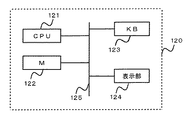
図6は、本発明の表示装置のシステム図である。表示装置120は、共通パス125にCPU121、メモリ(M)122、キーボード123、表示部124をつなげた構成であり、メモリ122には、図1に示した如き複数断層面の断層像が格納され、これをキーボード123の指示によりCPU121の働きで読み出し、表示部124に書く断層像順に表示する。そこから、操作者が表示画面を見て、P1,P2点を指示する。書く断層像の順次表示で手間がかかる故に、全断層像を三次元的に表示させて、そこからP1,P2点を指示するやり方もある。
FIG. 6 is a system diagram of the display device of the present invention. The
更に、図6では、P1,P2点を通る平面Q1、Q2を手動又は自動にて指定する。例えばキーボード123で指示する。CPU121は、この指示を受けて、平面Q1、Q2の新断層像データR1、R2を算出する。
Further, in FIG. 6, planes Q1 and Q2 passing through points P1 and P2 are designated manually or automatically. For example, an instruction is given using the
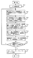
図7は、図6での処理フローを示す、ステップS20でCT画像を取得してメモリ122に格納する。ステップS21は、必要な断層面のCT画像を順次表示させて、その中から挿入点となる断層面Mk、到達点となる断層面Miを選択し指示する。ステップS22は、その断層面Mk、Mi上で点P1,P2を指定する。ステップS23では点P1,P2を通る第1平面Q1、第2平面Q2を指定し、ステップS24でその画素値を算出し、ステップS24で表示を行う。表示を見て適切な経路か否か判断し、不適切であればステップS21に戻り、適切であれば、Mj、Mk、P1、P2 、Q1、Q2並びに挿入角度θとして決定する。
FIG. 7 shows the processing flow in FIG. 6, and a CT image is acquired in step S <b> 20 and stored in the
病巣部位が複数個点在している例がある。これは、X、Y、Z軸でみると、P2の座標X、Y、Zがそれぞれ異なりP21(X、Y、Z)、P22(X、Y、Z)、P23(X3、Y3、Z3)、…であったりすることであり、基本的にはどれか1点を到達点として定め、他点はCT監視下で治療子を移動させるやり方をとる。この場合、事前にP1とP21、P1とP22、P1とP23の如き組合せで経路のチェックを、前述の如き新平面、新断層像を造り表示させて行い、全点に関しての障害等チェックを行うことが好ましい。 There is an example in which a plurality of lesion sites are scattered. This is because the coordinates X, Y, and Z of P2 are different from each other when viewed on the X, Y, and Z axes. P21 (X, Y, Z), P22 (X, Y, Z), P23 (X3, Y3, Z3) ,..., And basically, one of the points is determined as the reaching point, and the other point is a method of moving the treatment element under CT monitoring. In this case, the path is checked in advance by a combination of P1 and P21, P1 and P22, and P1 and P23, and the new plane and new tomographic image as described above are created and displayed, and all points are checked for failures. It is preferable.
次に、リアルタイムでのCT画像の形成法について説明する。
CT断層面M1、M2、…Mnのすべてについて治療子の位置いかんを問わず、その都度、計測し再構成する必要はない。治療子の現在位置を中心とするその近辺のみの断層面のCT画像を計測・再構成し、それ以外の断層面のCT画像はそれ迄に得た過去の画像を利用する。例えばある時点での治療子の先端位置をZiとしたとき、Zi近傍のi=i±γの幅内断層面(γは近傍値であり、数個の断層数〜数10個の断層数となる値である)で計測を行い、断層像を得る。かくして、リアルタイム性を維持してCT計測・再構成が可能となる。
この場合、Q1平面、Q2平面についてのCT断層面の中でi=i±γの断層面がリアルタイム性を維持したCT画素値を提供し、その他の断層面はその時点以前に計測・再構成したCT画素値である。
Next, a method for forming a CT image in real time will be described.
It is not necessary to measure and reconstruct the CT tomographic planes M1, M2,. The CT image of the tomographic plane only in the vicinity of the treatment element centered on the current position is measured and reconstructed, and the CT images of the other tomographic planes use the past images obtained so far. For example, when the tip position of a therapeutic element at a certain point in time is Zi, an in-width tomographic plane of i = i ± γ in the vicinity of Zi (γ is a nearby value, and several to tens of faults To obtain a tomographic image. Thus, CT measurement and reconstruction can be performed while maintaining real-time characteristics.
In this case, a CT pixel value in which the tomographic plane of i = i ± γ maintains a real-time property among the CT tomographic planes for the Q1 plane and the Q2 plane, and the other tomographic planes are measured and reconstructed before that point. CT pixel value obtained.
本発明の治療装置の実施例を説明する。
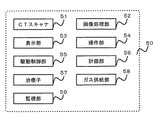
図8は、治療装置50の全体構成例図である。治療装置50は、CTスキャナ51、画像処理部52、表示部53、操作部54、駆動制御部55、計画部56、治療子57、ガス供給部58、監視部59、を具える。
An embodiment of the treatment apparatus of the present invention will be described.
FIG. 8 is an overall configuration example diagram of the
CTスキャナ51と画像処理部52と、表示部53と操作部54とは、本来のCT装置である。このCT装置を利用して事前に複数の断層像を取得し、三次元画像を形成しておく。複数の断層像から、更にその隙間を埋め合わせるための補間画像を三次元画像として利用する例もある。
The
CT装置51は、穿刺動作時のリアルタイムCT画像を得るのにも利用する。そしてこのリアルタイム画像は、監視部59での治療子57の穿刺動作をも併せて重ねて得ており、穿刺の追跡監視・治療監視に利用する。
計画部56は、画像処理部52と共同して、事前に得たデータに基づいて、又はこれと治療子57の形状(及び又は構造)データとに基づいて穿刺開始位置(挿入点)、治療部位(到達点)、その治療子の進行ルートの決定をデータ処理にて行い計画データを作成する。また熱持性や病巣部位物性値(生理値を含む)に基づくガス供給制御法を決定する。
The
The
駆動制御部55は、計画部56の計画データに基づいて治療子57の移動等の駆動制御並びにガス供給部58の供給制御を行い、凍結と解凍との交互動作を行う。
監視部59は、駆動制御の監視を行う。監視には、CT画像による監視と制御の仕組みの監視とがある。監視部59は、表示部53が兼務してもよい。
ここで、画像処理部52及び計画部56の一部が前記経路表示装置に相当する。
。この治療装置50は、治療子として凍結端子を用いた例であり、凍結端子及びその治療装置については先に示した先願がある。
The
The
Here, part of the
. This
本発明の治療装置50は、以下の処理及び動作を行う。
(1)凍結端子の穿刺入口位置P1と病巣位置P2とを決定する。この決定は、体軸方向に撮影・再構成した複数のCT断層像から選び、例えば断層面Ziの座標位置(Xa,Ya)をP1、断層面Zjの座標位置(Xb,Yb)をP2とする。選択の仕方は、例えばCT断層像を次々に体軸方向に沿って表示させ、操作者がZi、Zjの断層面、及びその面上の座標としての点P1、P2を指定するやり方、又は上記先願と同じく、体軸上に沿う三次元画像の三次元輪郭画像をみて決定する。
(2)点P1、P2とを通る平面Q1及びそれに直交する平面Q2、又は所定の角度をなす平面Q2を決定する。
これは画像処理部52と計画部56と用いてソフトウェアによる処理を利用する。
(3)駆動制御部56の働きにより穿刺動作を開始する。その監視は、監視部59で行う。穿刺動作の監視のために、X線CT装置によって、例えばマルチスライス計測(1回で複数断面の撮影を可能にする構造)によりCT撮影・再構成を行いCT断層像を得る。撮影範囲は、凍結端子の先端部近傍であり、凍結端子の穿刺の進行に併せて先端位置が進行し、その進行に応じて先端部近傍を次々にCT撮影・再構成を行いCT断層像を得る。
(4)CT監視下で得た最新断層像は、監視部59によって、メモリに記憶させた上で次々に表示部53に表示して進行の監視に利用する。これと併せて、画像処理部52と計画部56とで、本願発明の特徴の1つである上記(2)で決定したQ1、Q2平面上でのCT画素値を算出し、Q1、Q2平面上の画素位置(座標位置)対応に埋め込み断層像R1、R2を得、これを表示装置に表示する。
この断層像R1、R2を得るに際して、凍結端子の先端近傍に含まれる複数の断層面は、リアルタイムで得た断層画像を持つものであり、それ以外の断層面はそれ以前に得られた断層画像を持つものである。ここで、以前の断層像とは、穿刺動作に入る前に撮影して得た断層像又は先端位置の進行時にその先端位置よりも手前側で撮影して得た直前の断層像を含む。
(5)かくして、凍結端子の穿刺の経路を、最新のCT断層像及びQ1、Q2平面上での断層像が表示されることで、リアルタイムで監視できる。もし、経路をずれる様子があれば最新の断層像及びQ1、Q2平面上の断層像をみて凍結端子の方向の修正が可能となる。例えばQ1平面上で距離にして2mmずれとかQ2平面上で距離にして3mmずれとかの判断が可能となり、それを正しい経路に戻す操作を、凍結端子に行う。凍結端子がアクチュエーターで自動的に動くのであれば、その修正動作指令を与えたり、操作者の手動で行っているのであれば、手動操作で正規経路に戻す。
The
(1) The puncture entrance position P1 and the lesion position P2 of the freezing terminal are determined. This determination is made by selecting from a plurality of CT tomographic images photographed and reconstructed in the body axis direction. For example, the coordinate position (Xa, Ya) of the tomographic plane Zi is P1, and the coordinate position (Xb, Yb) of the tomographic plane Zj is P2. To do. For example, CT tomograms are displayed along the body axis direction one after another, and the operator designates the tomographic planes of Zi and Zj and the points P1 and P2 as coordinates on the plane, or the above As in the previous application, the determination is made by looking at the three-dimensional contour image of the three-dimensional image along the body axis.
(2) A plane Q1 passing through the points P1 and P2 and a plane Q2 orthogonal thereto or a plane Q2 forming a predetermined angle are determined.
This uses the processing by software using the
(3) The puncture operation is started by the action of the
(4) The latest tomographic image obtained under CT monitoring is stored in the memory by the
When obtaining the tomographic images R 1 and R 2 , a plurality of tomographic planes included in the vicinity of the tip of the freezing terminal have tomographic images obtained in real time, and other tomographic planes were obtained before that. It has a tomographic image. Here, the previous tomographic image includes a tomographic image obtained before entering the puncturing operation or a previous tomographic image obtained by photographing on the near side of the tip position when the tip position advances.
(5) Thus, the path of the puncture of the frozen terminal can be monitored in real time by displaying the latest CT tomographic image and the tomographic image on the Q1 and Q2 planes. If there is a situation where the path is deviated, the direction of the freezing terminal can be corrected by looking at the latest tomographic image and the tomographic images on the Q1 and Q2 planes. For example, it is possible to determine whether the distance on the Q1 plane is 2 mm or the distance on the Q2 plane is 3 mm, and the operation of returning it to the correct path is performed on the freezing terminal. If the freezing terminal is automatically moved by the actuator, the corrective operation command is given, or if it is manually performed by the operator, the operation is manually returned to the normal route.
本発明は、穿刺経路計画の作成や確認用にも使用できるので、以下説明する。
経路計画の作成や確認用では、リアルタイム性は不要であるので、すべて作成や確認のために事前に撮影・再構成した断層像を使う。こうした断層像を記憶装置に格納させた上で、P1、P2とを通る2つの平面Q1、Q2の断層像を作成(算出)し表示させて、P1、P2との確定を行う。ここで、P2は病巣部位であるため固定であり、従ってP1をどこに設定するかがポイントである。かかる適切なP1を売るために平面Q1、Q2の断層像を作成表示させ、探索し確定する。以上は作成用であるが、別法により作成したP1とP2との経路確認時にも、同様の表示を行って適切な設定であるか否かを確認できる。
以上の実施例では、凍結端子の事例としたが、それ以外の治療子、例えば患部をはぎとってくる、検査や治療のための素子、患部の監視のために侵入する素子(超小型カメラや光ファイバー端子)、超音波は電磁波などのエネルギーを患部に照射する素子、等種々のものに適用できる。
Since the present invention can be used for creating and confirming a puncture route plan, it will be described below.
Real time is not necessary for creating and confirming a route plan, so all tomographic images taken and reconstructed in advance are used for creation and confirmation. After storing such tomographic images in the storage device, tomographic images of two planes Q1 and Q2 passing through P1 and P2 are created (calculated) and displayed, and P1 and P2 are determined. Here, since P2 is a lesion site, it is fixed, so the point is where P1 is set. In order to sell such an appropriate P1, tomographic images of the planes Q1 and Q2 are created and displayed, searched and determined. Although the above is for preparation, it is possible to confirm whether or not the setting is appropriate by performing the same display even when confirming the route between P1 and P2 created by another method.
In the above embodiment, the case of the freezing terminal is taken as an example. However, other therapeutic elements, for example, an element for inspection or treatment that peels off the affected area, an intruding element for monitoring the affected area (an ultra-small camera, The optical fiber terminal) and the ultrasonic wave can be applied to various elements such as an element that irradiates the affected area with energy such as electromagnetic waves.
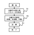
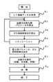
図9は、凍結端子を治療子とする治療装置の処理フローを示す。ステップS1では、CT画像データを体軸方向に沿って複数枚(数10枚以上)取得する。これはCT装置による。また事前にCT装置で取得してメモリに格納した被検体のメモリへの格納画像を用いることもある。
ステップS2は、侵入用パラメータである挿入点、治療対象である病巣部位の目標点、挿入角度より成る治療子パラメータを決定する。このステップS2では、本願発明の穿刺経路表示装置を利用する。
ステップS3は、そのパラメータを用いての実際の穿刺及び治療の動作を行う。治療に際しては、病巣目標点に到達したならば凍結と解凍とを凍結端子の先端部で繰返させて病巣の壊死を行う。この動作は、自動、半自動、手動のいずれでもよい。
FIG. 9 shows a processing flow of a treatment apparatus using a freezing terminal as a treatment child. In step S1, a plurality (several tens or more) of CT image data are acquired along the body axis direction. This is due to the CT apparatus. In addition, an image stored in the memory of the subject acquired in advance by the CT apparatus and stored in the memory may be used.
In step S2, a treatment parameter including an insertion point as an intrusion parameter, a target point of a lesion site to be treated, and an insertion angle is determined. In this step S2, the puncture route display device of the present invention is used.
In step S3, actual puncture and treatment operations are performed using the parameters. In the treatment, if the lesion target point is reached, the lesion is necrotized by repeating freezing and thawing at the tip of the freezing terminal. This operation may be automatic, semi-automatic, or manual.
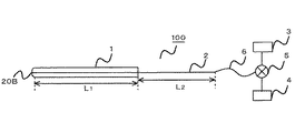
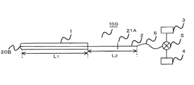
図10は、凍結端子である治療子100の概略図である。治療子100は、二重管(一重管の例もある。以下同じ。)1と凍結端子本体2、及びそれにつながる管路6、切替バルブ5、高圧ヘリウムガス供給源3、高圧アルゴンガス供給源4、より成る。管1の長さL1、凍結端子本体2の外部露出部の長さL2とすると、この治療子100は略(L1+L2)の長さの直線成分と考えてよく、かかる直線成分を刃物状の最先端20Bから挿入点P1から病巣部位の一点である目標点P2にまで侵入させてゆくことを想定して、その時の挿入角度θ,P1,P2,P1→P2(ルート)を算出できる。
FIG. 10 is a schematic view of the
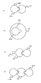
凍結端子100の二重管の先端部に方向によって熱持性を異ならしめた例を図11、図12に示す。管の先端は、凍結と解凍との2つの動作部位であり、いわゆる熱交換機能を果たす。癌病巣である病巣部位も種々の形状を有し、どのような方向から穿刺するのが効率的凍結法であるかも重要な検討事項である。更に病巣に近接する正常組織を凍結・解凍(特に凍結)から保護する必要もある。そこで方向性のある熱の指向特性に大小を持たせて病巣部位に応じた集中的に熱エネルギー付与のための熱分布特性を与える。これが図12に示す管の実施例図である。
FIGS. 11 and 12 show examples in which the heat retention is made different depending on the direction of the tip of the double tube of the freezing
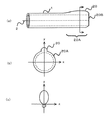
図11(a)は、二重金属管1の最先端20Bの直前の先端部20Aの周囲の一部を突起させて突起部20を設けた例である。その矢印断面は、図11(b)に示すように外方に向かって丸みを帯びた形状であり、その熱指向特性は図11(c)となる。先端部20Aの最先端20Bは穿刺の先端で刃物状であり、穿刺しやすく、且つ深部方向に熱指向特性を持たせるようにする例もある。
FIG. 11A shows an example in which a protruding
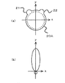
図12(a)は、先端部20Aに、2つの突起部21,22を持たせて熱指向特性を細長くさせた例である。これによって、図12(b)に示すようにy方向の(+)方向に鋭い熱指向特性を持たせた。
先端部20A及び20Bは、凍結・解凍に関与する部位である。
FIG. 12A shows an example in which the
The
図13に、この先端形状に特徴を持つ治療子の使用例を示す。図13(a)は、球形状の癌病巣23の側面に治療子100を穿刺させて癌病巣23をその指向特性に基づいて熱エネルギーを与えて壊死させる例を示す。この癌病巣23は、組織的にしっかりした例であり、病巣23に直接穿刺させるよりは囲りから壊死させるに適したものである。
図13(b)は癌病巣24の内部左側に穿刺し、右側への方向性を持つ治療子100で治療させた例である。これも、病巣全体の壊死に役立つ。
図13(c)は、血管24が近くにあり、この血管24から遠ざけて病巣23を治療を行なうときの事例である。血管24の反対側(右側)に治療子100を穿刺した。これは、血管を傷つけないことの他に、血管の温度の治療への影響を少なくしたいこと、の目的を持つ。図13(d)は、2つ以上の治療子100A,100Bを用いて、病巣23の両側に穿刺して同時治療を行なった例である。図13(d)は、病巣サイズが大きい事例に効果を持つ。
FIG. 13 shows an example of use of a treatment element characterized by this tip shape. FIG. 13A shows an example in which the
FIG. 13B shows an example in which the left side inside the
FIG. 13C shows a case where the
以上の各実施例で、突起形状の種類や態様は、どのような指向特性を持たせるかで定まる。突起形状の代わりに内側方向に凹部を持たせるやり方もある。指向特性を実現する突起形状(凹部を含む)は、計算機によって求めることができる。種々の突起形状の管を用意しておき、病巣や治療の目的に沿って使い分けるやり方もある。 In each of the embodiments described above, the type and form of the protrusion shape are determined by what directivity characteristics are given. There is also a method of providing a recess in the inner direction instead of the protrusion shape. The projection shape (including the concave portion) that realizes the directivity can be obtained by a computer. There is a way to prepare tubes with various protrusions and use them properly according to the focus and purpose of treatment.
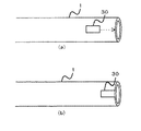
図14(a)は、二重管の他の実施例図である。図11では、固定突起形状化したが、図14では可動翼30を二重管1の外部側面に沿って設けておき、この可動翼30を、管の先端部まで図14(b)の如く移動させ、図11の如き突起状形状化させる。可動翼30は例えばスプリングで移動させる。これは、例えば凍結端子の進行に応じてスプリングを凍結端子に連動させるやり方をとる。この場合、可動翼30が人体を傷つけないように周囲に丸みを作っておく。
使い方は、人体挿入時には、図14(a)の如くしておき、患部到達時に図15(b)の如く移動させて使う。
FIG. 14A is a diagram showing another embodiment of the double pipe. In FIG. 11, the shape of the fixed protrusion is formed. However, in FIG. 14, the
When the human body is inserted, it is used as shown in FIG. 14A, and when it reaches the affected part, it is moved as shown in FIG. 15B.
図15は、凍結端子本体2の途中に操作に便となる操作(タッチ)部21Aを設けた実施例を示す。タッチ部21Aは手で握れる程度の大きさがあればよく、例えば端子本体2の直交方向に若干延びたバー形状体である。タッチ部21Aによって、凍結端子本体2の進行、端子自体の回転(Φ)を確実に行える利点がある。このタッチ部にアクチュエーターをつけておくことで、自動化、半自動化の操作が可能となる。
FIG. 15 shows an embodiment in which an operation (touch)
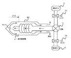
図16は凍結端子の具体例図である。40が凍結端子本体であり、熱伝導性の低い素材、例えば金属より成り、その内部には、熱交換機構41を持つ。切替バルブ5を介して高圧ガスが流入し、その先端開放部42から本体40の内側に放出し外部へ排気を行う。尚、31、32は各ガス毎のコックである。
FIG. 16 is a specific example of a freezing terminal.
温度特性(温度変化)について説明する。
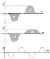
その具体例を図17に示す。図17(a)は、凍結ピーク温度と解凍ピーク温度とを同一絶対値T1(実際には凍結時−T1、解凍時+T1)とした1サイクル例である。両者で熱エネルギーが相殺されることが好ましいため、凍結時と解凍時との(温度)×(時間)で定まる面積は同一面積(S1)とする。図17(b)は、凍結ピーク温度と解凍ピーク温度との絶対値をT1、T2(T1>T2)とした例である。T1>T2の故に、同一面積S1の達成のために、解凍期間を凍結期間よりも大きくとる。尚、17(a)、(b)の変形例として、凍結1回、解凍2回で1サイクルの如き例もありうる。
図17(c)は凍結と解凍との2サイクル供与例である。3サイクル以上の例もある。
尚、面積を凍結と解凍とで同一としたが、病巣の壊死という目的達成が得られるのであれば、厳密な同一性は必要ない。人間の治療部位には38℃とかの体温がある故に、かかる体温を考慮して、実際の温度特性を定めることが多い。
かかる種々の温度特性(温度変化)を実現するためには、治療子100へのヘリウムとアルゴンとの両者のガス供給を、量と時間とをパラメータとして制御すればよい。
The temperature characteristic (temperature change) will be described.
A specific example is shown in FIG. FIG. 17A shows an example of one cycle in which the freezing peak temperature and the thawing peak temperature are set to the same absolute value T1 (actually -T1 during freezing and + T1 during thawing). Since it is preferable that the thermal energy be offset by both, the area determined by (temperature) × (time) during freezing and thawing is the same area (S1). FIG. 17B shows an example in which the absolute values of the freezing peak temperature and the thawing peak temperature are T1 and T2 (T1> T2). Since T1> T2, in order to achieve the same area S1, the thawing period is set longer than the freezing period. In addition, as a modified example of 17 (a) and (b), there can be an example of one cycle of one freezing and two thawings.
FIG. 17C shows an example of two-cycle donation including freezing and thawing. There are also examples of more than 3 cycles.
Although the area is the same for freezing and thawing, strict identity is not required if the goal of necrosis of the lesion can be achieved. Since a human treatment site has a body temperature of 38 ° C., an actual temperature characteristic is often determined in consideration of such body temperature.
In order to realize such various temperature characteristics (temperature changes), the gas supply of both helium and argon to the
温度特性(温度変化)の実現化及びガス供給制御法の決定について説明する。
i.被検体病巣部位の比熱、導伝率などの熱的定数及び体積重量を取り入れた病巣部位の形状などの物理的定数を考慮して、その物体の温度の時間変化を決定する。
ii.被検体の熱的定数、物理定数を考慮した侵入具到達点周辺の時間に対する温度変化を計算し、設定温度に対する動的変化又は動的変化に至る設定時間を決定し得る如く定める。
iii.この定めた到達点近傍の熱的時間変化について設定目的の温度変化となる様に侵入具の回転角を決定する。
iv.書く熱持性の異なる複数の侵入具の挿入に対する、到達点部位及びその近傍周辺の部位の熱的温度の時間変化を決定する。
v.この複数の熱的方向性を有した侵入具が上記決定された幾可学的定数のもとで侵入具が到達点及びその近傍において熱的温度の時間変化を繰り返し、試験操作を行いその結果から被検体への侵入開始位置、侵入具の輪郭上の到達点、侵入方向、侵入具の角度及び回転角、開始位置から到達点までの進行ルート、の少なくともいずれか1つを求め決定しかつ周辺物体の温度分布及び時間変化を決定する。
vi.上記侵入具の先端に装備された熱交換器の発熱、吸熱を切換えるガス流入路のガス切換えスイッチを到達点近傍の定められた温度変化になるようなガス量と供給シーケンス(タイミング)とのガス供給制御法を求める。治療時には、侵入用パラメータに従って穿刺を行い、治療部位到達後には上記ガス供給制御法によってガス供給を行う。
Realization of temperature characteristics (temperature change) and determination of a gas supply control method will be described.
i. Taking into account the thermal constants such as specific heat and conductivity of the subject lesion site and physical constants such as the shape of the lesion site incorporating the volume weight, the time change of the temperature of the object is determined.
ii. The temperature change with respect to the time around the intruder arrival point in consideration of the thermal constant and physical constant of the subject is calculated, and determined so that the dynamic change with respect to the set temperature or the set time to reach the dynamic change can be determined.
iii. The rotation angle of the intruder is determined so that the thermal change in the vicinity of the determined arrival point becomes the set temperature change.
iv. The time change of the thermal temperature of the reaching point part and the vicinity of the vicinity is determined with respect to the insertion of a plurality of intruders having different heat retention properties.
v. The intruder having the plurality of thermal directions is subjected to the test operation by repeating the temporal change of the thermal temperature at the arrival point and the vicinity thereof under the determined geometrical constant as a result. Determining and determining at least one of the entry start position from the object to the subject, the arrival point on the contour of the entry tool, the entry direction, the angle and rotation angle of the entry tool, and the travel route from the start position to the arrival point; Determine the temperature distribution and temporal changes of surrounding objects.
vi. A gas changeover switch in the gas inflow passage that switches between heat generation and heat absorption of the heat exchanger installed at the tip of the intruder is a gas with a gas amount and a supply sequence (timing) such that the temperature changes in the vicinity of the arrival point. Find the supply control method. At the time of treatment, puncture is performed according to the intrusion parameters, and gas supply is performed by the gas supply control method after reaching the treatment site.
図18は、温度特性を考慮した処理フローを示す。図9に比べて、ステップS2とS3との間に新たなステップS5、S6、S7を付加した。ステップS5では、前述の温度特性の決定、及びそれに基づくガス供給制御法の算出を行う。ステップS6はステップS2、S58で算出したパラメータ、温度特性、並びにガス供給制御法に基づく治療シミュレーションを行う。シミュレーションの結果、治療効果がないとの判定であればステップS2へ戻る。治療効果があるとの判定であればステップS7へ進み、最終決定を行う。 FIG. 18 shows a processing flow in consideration of temperature characteristics. Compared to FIG. 9, new steps S5, S6, and S7 are added between steps S2 and S3. In step S5, the above-described temperature characteristics are determined, and the gas supply control method based on the temperature characteristics is calculated. In step S6, a treatment simulation based on the parameters calculated in steps S2 and S58, the temperature characteristics, and the gas supply control method is performed. As a result of the simulation, if it is determined that there is no therapeutic effect, the process returns to step S2. If it is determined that there is a therapeutic effect, the process proceeds to step S7 and a final decision is made.
1 1重又は2重の金属管
2 凍結端子本体
100 治療子
110 被検体
1 Single or
Claims (6)
上記三次元画像における被検体侵入具の侵入点と被検体内到達点とを設定する手段と、
この侵入点と到達点を通る第1平面、及びこの侵入点と到達点とを通り上記第1平面に所定角度をなす第2平面を設定する手段と、
第1平面と上記三次元画像データの各断層面との交点の画素値、又は交点近傍の画素値から近似した画素値を、第1平面の交点の画素値として決定し、かくして第1平面の断層画像データを算出する第1の算出手段と、
第2平面と上記三次元画像データの各断層面との交点の画素値、又は交点近傍の画素値から近似した新画素値を、第2平面の交点の画素値として決定し、かくして第2平面の断層画像データを算出する第2の算出手段と、
上記算出した第1平面の断層像、第2平面の断層像を表示する表示手段と、
を備える治療子経路表示装置。 Storage means for storing three-dimensional image data obtained by superimposing tomographic images obtained by imaging a subject in a direction perpendicular to the tomographic plane;
Means for setting the entry point of the subject entry tool and the in-subject arrival point in the three-dimensional image;
Means for setting a first plane passing through the entry point and the arrival point, and a second plane passing through the entry point and the arrival point and forming a predetermined angle with the first plane;
A pixel value approximated from a pixel value at an intersection of the first plane and each tomographic plane of the three-dimensional image data or a pixel value in the vicinity of the intersection is determined as a pixel value at the intersection of the first plane, and thus the first plane First calculation means for calculating tomographic image data;
The pixel value at the intersection of the second plane and each tomographic plane of the 3D image data or a new pixel value approximated from the pixel value near the intersection is determined as the pixel value at the intersection of the second plane, and thus the second plane Second calculating means for calculating the tomographic image data of
Display means for displaying the calculated tomographic image of the first plane and the tomographic image of the second plane;
A therapeutic child route display device.
3D image data obtained by superimposing tomographic images obtained by imaging a subject in a direction perpendicular to the tomographic plane and obtaining the 3D image data of a straight line obtained by connecting the object intruder entry point and the arrival point; Intruder insertion device with a certain angle.
Priority Applications (1)
| Application Number | Priority Date | Filing Date | Title |
|---|---|---|---|
| JP2006034911A JP2007209651A (en) | 2006-02-13 | 2006-02-13 | Therapeutic element passage display device |
Applications Claiming Priority (1)
| Application Number | Priority Date | Filing Date | Title |
|---|---|---|---|
| JP2006034911A JP2007209651A (en) | 2006-02-13 | 2006-02-13 | Therapeutic element passage display device |
Publications (1)
| Publication Number | Publication Date |
|---|---|
| JP2007209651A true JP2007209651A (en) | 2007-08-23 |
Family
ID=38488556
Family Applications (1)
| Application Number | Title | Priority Date | Filing Date |
|---|---|---|---|
| JP2006034911A Withdrawn JP2007209651A (en) | 2006-02-13 | 2006-02-13 | Therapeutic element passage display device |
Country Status (1)
| Country | Link |
|---|---|
| JP (1) | JP2007209651A (en) |
Cited By (5)
| Publication number | Priority date | Publication date | Assignee | Title |
|---|---|---|---|---|
| WO2012147652A1 (en) * | 2011-04-27 | 2012-11-01 | 株式会社デージーエス・コンピュータ | Puncture treatment support method, puncture treatment support device, and program for puncture treatment support device |
| EP2526869A2 (en) | 2011-05-23 | 2012-11-28 | Fujifilm Corporation | Image processing device, radiographic image capture system, image processing method and image processing program storage medium |
| JP2013154161A (en) * | 2012-06-14 | 2013-08-15 | Toshiba Corp | X-ray ct apparatus |
| JP2017051649A (en) * | 2016-11-16 | 2017-03-16 | 東芝メディカルシステムズ株式会社 | X-ray ct apparatus and x-ray ct system |
| JP2018505010A (en) * | 2015-02-23 | 2018-02-22 | クール セラピューティクス, インコーポレイテッド | System and method for intratracheal delivery of frozen particles |
-
2006
- 2006-02-13 JP JP2006034911A patent/JP2007209651A/en not_active Withdrawn
Cited By (6)
| Publication number | Priority date | Publication date | Assignee | Title |
|---|---|---|---|---|
| WO2012147652A1 (en) * | 2011-04-27 | 2012-11-01 | 株式会社デージーエス・コンピュータ | Puncture treatment support method, puncture treatment support device, and program for puncture treatment support device |
| EP2526869A2 (en) | 2011-05-23 | 2012-11-28 | Fujifilm Corporation | Image processing device, radiographic image capture system, image processing method and image processing program storage medium |
| JP2012239745A (en) * | 2011-05-23 | 2012-12-10 | Fujifilm Corp | Image processing device, radiation imaging system, image processing program and image processing method |
| JP2013154161A (en) * | 2012-06-14 | 2013-08-15 | Toshiba Corp | X-ray ct apparatus |
| JP2018505010A (en) * | 2015-02-23 | 2018-02-22 | クール セラピューティクス, インコーポレイテッド | System and method for intratracheal delivery of frozen particles |
| JP2017051649A (en) * | 2016-11-16 | 2017-03-16 | 東芝メディカルシステムズ株式会社 | X-ray ct apparatus and x-ray ct system |
Similar Documents
| Publication | Publication Date | Title |
|---|---|---|
| US8155416B2 (en) | Methods and apparatuses for planning, performing, monitoring and assessing thermal ablation | |
| JP7326304B2 (en) | Volumetric image processing | |
| US7871406B2 (en) | Methods for planning and performing thermal ablation | |
| EP3240492B1 (en) | System for treating copd and emphysema | |
| JP5095149B2 (en) | Simulation of invasive procedures | |
| US20080033417A1 (en) | Apparatus for planning and performing thermal ablation | |
| JP4448818B2 (en) | Medical equipment | |
| JP5348889B2 (en) | Puncture treatment support device | |
| US20080033419A1 (en) | Method for planning, performing and monitoring thermal ablation | |
| JP7538214B2 (en) | Systems and methods for monitoring resection procedures - Patents.com | |
| WO2012147652A1 (en) | Puncture treatment support method, puncture treatment support device, and program for puncture treatment support device | |
| EP2068736A1 (en) | Methods and systems for planning, performing and monitoring thermal ablation | |
| JP2007038005A (en) | Guided procedure for treating atrial fibrillation | |
| JP2013135738A (en) | Operation support system | |
| JP5731267B2 (en) | Treatment support system and medical image processing apparatus | |
| CN105007815A (en) | Organ mapping system using an optical coherence tomography probe | |
| CN116327365B (en) | Biopsy system based on electromagnetic positioning and navigation method | |
| JP4807830B2 (en) | Diagnostic imaging apparatus and treatment support system | |
| JP4744284B2 (en) | Treatment child | |
| JP2018175688A (en) | Body tissue position measuring device and radiation treatment device, and body tissue position measuring method | |
| CN117598774A (en) | An interventional ablation method and system | |
| JP4514438B2 (en) | Treatment device control system | |
| EP4153085B1 (en) | System for independently positioning an ablation tool and imaging device | |
| CN113488177A (en) | Lung modeling method and system based on image data | |
| CN112370162A (en) | Method for establishing image model puncture ablation path through multiple constraints |
Legal Events
| Date | Code | Title | Description |
|---|---|---|---|
| A300 | Application deemed to be withdrawn because no request for examination was validly filed |
Free format text: JAPANESE INTERMEDIATE CODE: A300 Effective date: 20090512 |