JP2007219002A - Image forming apparatus - Google Patents
Image forming apparatus Download PDFInfo
- Publication number
- JP2007219002A JP2007219002A JP2006036851A JP2006036851A JP2007219002A JP 2007219002 A JP2007219002 A JP 2007219002A JP 2006036851 A JP2006036851 A JP 2006036851A JP 2006036851 A JP2006036851 A JP 2006036851A JP 2007219002 A JP2007219002 A JP 2007219002A
- Authority
- JP
- Japan
- Prior art keywords
- charging roll
- image forming
- image
- forming apparatus
- roll
- Prior art date
- Legal status (The legal status is an assumption and is not a legal conclusion. Google has not performed a legal analysis and makes no representation as to the accuracy of the status listed.)
- Granted
Links
Images
Classifications
-
- G—PHYSICS
- G03—PHOTOGRAPHY; CINEMATOGRAPHY; ANALOGOUS TECHNIQUES USING WAVES OTHER THAN OPTICAL WAVES; ELECTROGRAPHY; HOLOGRAPHY
- G03G—ELECTROGRAPHY; ELECTROPHOTOGRAPHY; MAGNETOGRAPHY
- G03G15/00—Apparatus for electrographic processes using a charge pattern
- G03G15/02—Apparatus for electrographic processes using a charge pattern for laying down a uniform charge, e.g. for sensitising; Corona discharge devices
-
- G—PHYSICS
- G03—PHOTOGRAPHY; CINEMATOGRAPHY; ANALOGOUS TECHNIQUES USING WAVES OTHER THAN OPTICAL WAVES; ELECTROGRAPHY; HOLOGRAPHY
- G03G—ELECTROGRAPHY; ELECTROPHOTOGRAPHY; MAGNETOGRAPHY
- G03G15/00—Apparatus for electrographic processes using a charge pattern
- G03G15/02—Apparatus for electrographic processes using a charge pattern for laying down a uniform charge, e.g. for sensitising; Corona discharge devices
- G03G15/0208—Apparatus for electrographic processes using a charge pattern for laying down a uniform charge, e.g. for sensitising; Corona discharge devices by contact, friction or induction, e.g. liquid charging apparatus
- G03G15/0216—Apparatus for electrographic processes using a charge pattern for laying down a uniform charge, e.g. for sensitising; Corona discharge devices by contact, friction or induction, e.g. liquid charging apparatus by bringing a charging member into contact with the member to be charged, e.g. roller, brush chargers
- G03G15/0225—Apparatus for electrographic processes using a charge pattern for laying down a uniform charge, e.g. for sensitising; Corona discharge devices by contact, friction or induction, e.g. liquid charging apparatus by bringing a charging member into contact with the member to be charged, e.g. roller, brush chargers provided with means for cleaning the charging member
Landscapes
- Physics & Mathematics (AREA)
- Engineering & Computer Science (AREA)
- Plasma & Fusion (AREA)
- General Physics & Mathematics (AREA)
- Electrostatic Charge, Transfer And Separation In Electrography (AREA)
Abstract
Description
本発明は、電子写真方式の画像形成装置に関し、特に、感光体に当接して感光体表面を帯電する接触式帯電ロールの移動防止を図った画像形成装置に関するものである。
BACKGROUND OF THE
従来の画像形成装置の接触式帯電装置の一例として、帯電電圧が印加された帯電部材を像担持体である感光体ドラムに圧接するようにバネを用いて弾性支持し、この感光体ドラムに電荷を直接的に転移させることによって感光体ドラムの表面を所定の電位に帯電し、該帯電部材を圧接部での接触摩擦力を利用して感光体ドラムの回転に従動回転させるものが知られている。 As an example of a contact-type charging device of a conventional image forming apparatus, a charging member to which a charging voltage is applied is elastically supported using a spring so as to be pressed against a photosensitive drum as an image carrier, and the photosensitive drum is charged. It is known that the surface of the photosensitive drum is charged to a predetermined potential by directly transferring the rotation of the photosensitive drum, and the charging member is rotated by the rotation of the photosensitive drum using the contact friction force at the press contact portion. Yes.
しかし、このように帯電部材を感光体ドラムに従動回転させる場合には、感光体ドラムから回転駆動を受ける際にその摩擦駆動力により引きずられ感光体ドラムに対する帯電部材の軸方向の位置が所定の位置に対し変動し、これにより圧接部のニップ不均一や荷重不均一が生じ、経時的に感光体ドラムの磨耗ムラや最終的に画像濃度ムラを引きおこしてしまうという問題がある。 However, when the charging member is driven to rotate by the photosensitive drum in this way, the position of the charging member in the axial direction relative to the photosensitive drum is dragged by the frictional driving force when receiving rotational driving from the photosensitive drum. There is a problem that the nip and non-uniformity of the nip of the pressure contact portion are caused by the position, thereby causing uneven wear of the photosensitive drum and eventually uneven image density.
このような問題に対し、一般的な対策として帯電部材の軸受けやハウジング等の剛性アップや補強部材の取り付けなどによる強度アップが考えられるが、近年の装置の小型化(小スペース化)やコストダウンといった要請に逆行し、また、帯電部材の過剰な剛性アップは摺動性低下につながり感光体ドラムに対する圧接不良が発生するといった問題が生じていた。 As a general countermeasure against such problems, it is conceivable to increase the rigidity of bearings and housings of charging members and to increase the strength by attaching reinforcing members, but in recent years miniaturization of devices (smaller space) and cost reduction Further, there has been a problem that an excessive increase in rigidity of the charging member leads to a decrease in slidability and a poor press contact with the photosensitive drum.
さらに、近年は、信頼性や長寿命化の観点より、帯電部材の外周面にクリーニング部材を設けるなど構成が複雑化(部品点数の増加)しており、一層各部品および部品間の位置ずれが生じ易くなっている。 Furthermore, in recent years, from the viewpoint of reliability and longer life, the configuration has become complicated (increase in the number of parts), such as providing a cleaning member on the outer peripheral surface of the charging member, and the positional deviation between each part and parts has further increased. It tends to occur.
そこで、このような接触式帯電ロールの位置ずれを防止する提案がなされている(例えば、特許文献1参照)。 In view of this, a proposal has been made to prevent such displacement of the contact-type charging roll (for example, see Patent Document 1).
この特許文献1に開示された先行技術では、感光体ドラムの回転時に、帯電ロールの初期位置に対し、該帯電ロールのずれ量が10mm以下に設定されるように画像形成装置の本体に回動自在に帯電ロールを支持し、感光体ドラムの回転により帯電ロールが回転方向にずれるのを阻止するためのスプリングを帯電ロールの保持部材の側方に配置して弾性支持する画像形成装置が開示されている。
In the prior art disclosed in
しかしながら、上述の特許文献に開示された先行技術においては、上述したように構成部品の数が増え、構成が複雑となり設置スペースやコストが増加するといった問題が生じていた。 However, in the prior art disclosed in the above-mentioned patent document, there has been a problem that the number of components increases as described above, the configuration becomes complicated, and the installation space and cost increase.
また、上述の先行技術においては、帯電ロールの軸ずれを所定の範囲内で許容するものであるが、近年の小型化された画像形成装置では、小径の感光体や帯電部材が採用されており、両部材間の軸ずれは、帯電性能ひいては画像形成性能に大きく影響するため基本的に帯電ロールの軸位置は移動しないことが望ましい。 Further, in the above-described prior art, the axis deviation of the charging roll is allowed within a predetermined range. However, recent downsized image forming apparatuses employ a small-diameter photoreceptor and a charging member. Since the axial displacement between the two members greatly affects the charging performance and thus the image forming performance, it is basically desirable that the axial position of the charging roll does not move.
そこで、本発明は、上述のような従来技術の問題点に鑑みてなされたものであり、像担持体の回転に伴う接触式帯電ロールの位置ずれを確実に防止することができる画像形成装置を簡易な構成で安価に提供することを目的とする。 Accordingly, the present invention has been made in view of the above-described problems of the prior art, and an image forming apparatus capable of reliably preventing the displacement of the contact-type charging roll accompanying the rotation of the image carrier. The purpose is to provide a simple configuration at low cost.
上記目的を達成するために、本発明の画像形成装置は、その表面に静電潜像が形成される回転自在の像担持体と、該像担持体に従動回転して像担持体の表面を所定の電位に帯電する帯電ロールと、前記帯電ロールの回転方向に沿って、前記像担持体と帯電ロールとのニップ部よりも下流側であって、かつ、前記像担持体の軸線と前記帯電ロールの軸線とから構成される平面に垂直で、前記帯電ロールの軸線を含んだ平面よりも上流側において、前記帯電ロールに接触するように配設された支持手段とを有することを特徴とするものである。 In order to achieve the above object, an image forming apparatus of the present invention includes a rotatable image carrier on which an electrostatic latent image is formed, and a surface of the image carrier that is rotated by the image carrier. A charging roll that is charged to a predetermined potential; and a downstream side of a nip portion between the image carrier and the charging roll along a rotation direction of the charging roll, and an axis of the image carrier and the charging roller And a support means disposed so as to come into contact with the charging roll at a position upstream of a plane including the axis of the charging roll and upstream of the plane including the axis of the charging roll. Is.
ここで、像担持体(帯電ロール)の軸線とは、像担持体(帯電ロール)の中心点を結んだ直線をいうものとする。 Here, the axis of the image carrier (charging roll) refers to a straight line connecting the center points of the image carrier (charging roll).
このように構成した本発明の画像形成装置は、回転自在の像担持体と、帯電ロールと、帯電ロールの回転方向に沿って、像担持体と帯電ロールとのニップ部よりも下流側であって、かつ、像担持体の軸線と帯電ロールの軸線とから構成される平面に垂直で、帯電ロールの軸線を含んだ平面よりも上流側において、前記帯電ロールに接触するように配設された支持手段とを有しているので、像担持体の回転に伴う帯電ロールの位置ずれを確実に防止することができる画像形成装置を簡易な構成で安価に実現することができる。 The image forming apparatus of the present invention configured as described above is downstream of the nip portion between the image carrier and the charging roll along the rotation direction of the rotatable image carrier, the charging roll, and the charging roll. And arranged perpendicular to the plane composed of the axis of the image carrier and the axis of the charging roll and in contact with the charging roll on the upstream side of the plane including the axis of the charging roll. Therefore, the image forming apparatus capable of reliably preventing the displacement of the charging roll accompanying the rotation of the image carrier can be realized at low cost with a simple configuration.
また、前記帯電ロールに当接してその表面をクリーニングする帯電ロール用クリーニング部材をさらに備え、前記帯電ロール用クリーニング部材は、前記支持手段を兼用してもよい。 In addition, a charging roll cleaning member that contacts the charging roll and cleans the surface thereof may be further provided, and the charging roll cleaning member may also serve as the support means.
このように構成した場合には、帯電ロール用クリーニング部材が、支持手段を兼用するので、部品点数の削減による装置小型化及びコストダウンに寄与することができる。 In such a configuration, the charging roll cleaning member also serves as the supporting means, which can contribute to downsizing and cost reduction of the apparatus by reducing the number of parts.
さらに、前記帯電ロール用クリーニング部材は、ロール状の回転部材であってもよい。 Further, the charging roll cleaning member may be a roll-shaped rotating member.
このように構成した場合には、帯電ロール用クリーニング部材が、ロール状の回転部材であるので、帯電ロールの回転負荷が軽減され、帯電ロールの回転の安定化に寄与することができる。 In such a configuration, since the charging roll cleaning member is a roll-shaped rotating member, the rotational load of the charging roll is reduced, which can contribute to stabilization of the rotation of the charging roll.
本発明によれば、像担持体の回転に伴う接触式帯電ロールの位置ずれの確実な防止を可能とする画像形成装置を簡易な構成で安価に実現することができる。 According to the present invention, an image forming apparatus that can reliably prevent displacement of a contact-type charging roll accompanying rotation of an image carrier can be realized with a simple configuration at low cost.
以下に、本発明に係る実施の形態を図面を参照して説明する。 Embodiments according to the present invention will be described below with reference to the drawings.
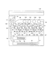
まず、本発明の一実施の形態に係る画像形成装置の概略構成について、図1を参照して説明する。図1は本発明に係わるタンデム型カラー画像形成装置100の概略構成図である。
First, a schematic configuration of an image forming apparatus according to an embodiment of the present invention will be described with reference to FIG. FIG. 1 is a schematic configuration diagram of a tandem color
この画像形成装置100においては、画像読取装置102より読み取られたカラー原稿のカラー画像情報、図示しないパーソナルコンピュータや画像データ入力装置等から送られてくるカラー画像情報等が入力され、入力された画像情報に対して画像処理が行われるようになっている。
In this
図1において、1Y,1M,1C,1Kは、それぞれイエロー(Y)、マゼンタ(M)、シアン(C)、ブラック(K)の各色トナー画像を形成する画像形成ユニットであり、複数の張架ロールにより張架された無端状の中間転写ベルト9の進行方向に沿って1Y,1M,1C,1Kの順で直列に配設されている。また、中間転写ベルト9は、これらの画像形成ユニット1Y,1M,1C,1Kで順次形成された各色のトナー像が、互いに重ね合わされた状態で転写される中間転写体であり、各画像形成ユニット1Y,1M,1C,1Kに対応する静電潜像担持体である感光体ドラム2Y,2M,2C,2Kのそれぞれに対向して配設される一次転写ロール6Y,6M,6C,6Kとの間に挿通され、矢印方向に循環移動可能に形成されている。そして、中間転写ベルト9上に多重に転写された各色のトナー像は、給紙カセット17等から給紙された記録媒体としての記録用紙18上に一括して転写された後、定着装置15によって記録用紙18上に定着され、カラー画像が形成された記録用紙18が外部に排出されるようになっている。
In FIG. 1, 1Y, 1M, 1C, and 1K are image forming units that form toner images of yellow (Y), magenta (M), cyan (C), and black (K), respectively. The endless
ここで、画像読取装置102は、プラテンガラス上に載置された原稿を不図示の光源によって照明し、原稿からの反射光像を、走査光学系を介してCCDセンサ等からなる画像読取素子によって所定の解像度で読み取るように構成されている。
Here, the
また、各画像形成ユニット1Y,1M,1C,1Kは、同様に構成されており、大別して、矢印方向に沿って所定の回転速度で回転する像担持体である感光体ドラム2Y,2M,2C,2Kと、この感光体ドラム2Y,2M,2C,2Kの表面を一様に帯電する帯電手段としての帯電ロール3Y,3M,3C,3Kと、当該感光体ドラム2Y,2M,2C,2Kの表面に各色に対応した画像を露光して静電潜像を形成する露光装置4Y,4M,4C,4Kと、感光体ドラム2Y,2M,2C,2K上に形成された静電潜像を現像する現像装置5Y,5M,5C,5Kと、着脱自在に配設され現像装置5Y,5M,5C,5Kに所定の色のトナーを供給するトナーカートリッジ10Y,10M,10C,10Kと、ドラムクリーニング装置7Y,7M,7C,7K等とから構成されている。
Each of the
さらに、本実施の形態において、感光体ドラム2Y,2M,2C,2Kは、矢印方向に回転する金属製ドラムの表面に有機系感光材料、アモルファスセレン系感光材料、アモルファスシリコン系感光材料等からなる感光層が被膜形成されており、帯電ロール3Y,3M,3C,3Kは、この感光体ドラム2Y,2M,2C,2Kの表面と接触し、直流電圧/電流に交流電圧/電流を重畳したバイアスにより、該感光層を所定の電位に帯電するように構成されている。
Further, in the present embodiment, the
また、本実施の形態では、帯電ロール3Y,3M,3C,3Kのそれぞれには、後述する不図示の帯電ロール用クリーニング部材が配設されており、この帯電ロール用クリーニング部材は、バネ等の弾性部材により、各帯電ロール3Y,3M,3C,3Kに対して所定の圧接力にて当接するように構成されている。
In the present embodiment, each of the
このように構成した画像形成装置における画像形成工程について、イエロートナー画像を形成する画像形成ユニット1Yを代表例として説明する。
The image forming process in the image forming apparatus configured as described above will be described using the
まず、感光体ドラム2Yは、所定の直流電圧/電流に交流電圧/電流が重畳されたバイアス電圧/電流が帯電ロール3Yに印加されることにより、その表面(感光層)が一様に帯電される。次に、例えば、画像読取装置102によって読み取られた画像情報に基づき、露光装置4Yから出力されるレーザービームによりイエロー画像に対応する走査露光がなされ、感光体ドラム2Yの表面(感光層)にはイエロー画像に対応する静電潜像が形成される。
First, the surface (photosensitive layer) of the
このイエロー画像に対応する静電潜像は現像装置5Yによってイエロートナー像となり、一次転写手段の一部を構成する一次転写ロール6Yの圧接力及び静電吸引力によって中間転写ベルト9上に一次転写される。一次転写後の感光体ドラム2Y上に残留したイエロートナーは、ドラムクリーニング装置7Yよって掻き取られる。その後、感光体ドラム2Yの表面は除電装置8Yによって除電された後、次の画像形成サイクルのために帯電ロール3Yにより再び帯電される。
The electrostatic latent image corresponding to the yellow image is converted into a yellow toner image by the developing
多色のカラー画像形成を行う本画像形成装置100では、各画像形成ユニット1Y,1M,1C,1Kの相対的な位置の違いを考慮したタイミングで、上記と同様の画像形成工程が画像形成ユニット1M,1C,1Kにおいても行われ、中間転写ベルト9上にフルカラートナー像が重ね合わされた状態で形成される。この中間転写ベルト9としては、例えば、可撓性を有するポリイミド等の合成樹脂フィルムを帯状に形成し、この帯状に形成された合成樹脂フィルムの両端を溶着等の手段によって接続することにより、無端ベルト状に形成したものが用いられる。
In the present
中間転写ベルト9上に一次転写されたフルカラートナー像は、所定のタイミングで二次転写位置へと搬送される記録用紙18上に、中間転写ベルト9を支持するバックアップロール13と、このバックアップロール13に所定のタイミングで圧接する二次転写ロール12との圧接力及び静電吸引力によって二次転写される。
The full-color toner image primarily transferred onto the
一方、記録用紙18は、画像形成装置100内の下部に配置された記録用紙収容部としての給紙カセット17から、所定のサイズのものが給紙ロール17aによって給紙される。給紙された記録用紙18は、複数の搬送ロール19及びレジストロール20によって、所定のタイミングで中間転写ベルト9の二次転写位置まで搬送される。そして、記録用紙18には、上述したように、二次転写手段としてのバックアップロール13と二次転写ロール12とによって、中間転写ベルト9上からフルカラートナー像が一括して転写される。
On the other hand, recording
また、中間転写ベルト9上からフルカラートナー像が二次転写された記録用紙18は、中間転写ベルト9から分離された後、二次転写手段の下流側に配設された定着装置15へと搬送され、この定着装置15によって熱及び圧力でトナー像が記録用紙18上に定着されるようになっている。定着後の記録用紙18は、排出ロール23を介して、排出トレイ24上に排出される。
The
さらに、二次転写手段により記録用紙18上に転写できなかった中間転写ベルト9上の残トナーは、そのまま中間転写ベルト9上に付着した状態でベルトクリーニング装置14まで搬送され、このベルトクリーニング装置14により中間転写ベルト9上から除去されて次の画像形成に備える。
Further, the residual toner on the
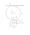
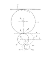
次に、本発明に係る帯電ロール及び帯電ロール用クリーニング部材の構成について、図2及び図3を参照してさらに説明する。図2は、本発明に係る帯電ロール用クリーニング部材の配置を模式的に示す図であり、図3は、従来の帯電ロール用クリーニング部材の配置を模式的に示す図である。ここで、各画像形成ユニット1Y〜1Kは同様な構成であり、これらの構成機器(例えば、感光体ドラム2Y〜2K)についても同様な構造であるため、以下、簡単のため、各符号は総称表記(例えば、感光体ドラム2)とする。
Next, the configuration of the charging roll and the charging roll cleaning member according to the present invention will be further described with reference to FIGS. FIG. 2 is a view schematically showing the arrangement of the charging roll cleaning member according to the present invention, and FIG. 3 is a view schematically showing the arrangement of the conventional charging roll cleaning member. Here, the
図2に示されるように、本実施の形態に係る画像形成装置は、回転自在に駆動される感光体ドラム2の表面に接触して、不図示の高圧電源より所定のバイアス電圧/電流が印加される接触式の帯電ロール3と、この帯電ロール3の表面に所定の圧接力にて当接するように、バネ等の弾性部材により支持された帯電ロール用クリーニング部材CLとを備えている。
As shown in FIG. 2, in the image forming apparatus according to the present embodiment, a predetermined bias voltage / current is applied from a high voltage power source (not shown) in contact with the surface of the
本実施の形態に係る帯電ロール3は、不図示の軸受け摺動部材により支持され、この軸受け部材の下方より押圧バネSにより一定荷重及び食込み量(本例では、0.2mm)にて、感光体ドラム2に当接され、ニップ部(圧接部)Nを形成している。また、帯電ロール3は、ニップ部Nの摩擦力により感光体ドラム2の回転に従動して感光体ドラム2と同速回転するようになっている。
The charging
ここで、帯電ロール3は、ステンレス等の金属からなる芯金の表面に、抵抗値が所定の値に調整された導電性の合成樹脂や合成ゴム等からなる導電層を被覆して構成されたロール状の回転部材であり、必要に応じて、導電層の表面にさらに離型層が形成されている。そして、芯金に、例えば、直流電圧が重畳された交流電圧を印加することによって、帯電ロール3と感光体ドラム2との間の微小ギャップにおいてギャップ放電を発生させ、当該放電によって感光体ドラム2の表面を所定の電位に帯電するようになっている。
Here, the charging
また、帯電ロール用クリーニング部材CLは、帯電ロール3と同様なロール状の回転部材であり、不図示の軸受け部材により支持され、帯電ロール3に対し所定の食込み量(本例では、0.75mm)となる軸間距離で帯電ロール3に当接してニップ部N1を形成すると共に、帯電ロール3の回転に従動するようになっている。なお、本実施の形態における帯電ロール用クリーニング部材CLは、例えば、SUS等のシャフト部材とスポンジとを備えている。スポンジは多孔質の弾性体であり、ウレタンスポンジやウレタンスポンジに比べ密着性の低い部材(例えば、メラミン樹脂等)により形成することができる。
Further, the charging roll cleaning member CL is a roll-like rotating member similar to the charging
ところで、一般に、画像形成装置においては、感光体ドラム2の周面に沿って、帯電ロール3と感光体ドラム2とのニップ部Nの下流側には、露光装置4(図1参照)によるレーザー照射面等の露光面や、現像装置5(図1参照)による現像面が形成されるため、従来の帯電ロール用クリーニング部材CL’は、このような領域を避けて配置され、本実施の形態のように、感光体ドラム2の下方に帯電ロール3が配置される構成の場合には、帯電ロール用クリーニング部材CL’は、図3に例示されるように、帯電ロール3の下方に配置するのが通常である。
Incidentally, in general, in an image forming apparatus, a laser beam from an exposure device 4 (see FIG. 1) is provided downstream of the nip portion N between the charging
しかし、例えば、帯電ロール3の中心から見て図中、右下半分の周面R’にてニップ部N1が形成されるように帯電ロール用クリーニング部材CL’を配置した場合でも、感光体ドラム2側に付勢された帯電ロール3には、感光体ドラム2の中心2o方向に押し付ける力と感光体ドラム2の回転方向(本例では、反時計回り方向)に引き摺る力(図中、右方向の力)とが作用するので、結果的に、帯電ロール3には、矢印Q方向(図中、右斜め上方向)に沿った力が作用することとなり、帯電ロール3は、帯電ロール用クリーニング部材CL’の周面を乗り越えるように破線部3’で示すような位置に移動してしまい、ニップ不均一や荷重不均一が生じ、経時的な感光体ドラム2の磨耗むらや帯電不良等に伴う画像欠陥が発生することが本発明者らの研究により判明した。
However, for example, even when the charging roll cleaning member CL ′ is arranged so that the nip portion N1 is formed on the peripheral surface R ′ in the lower right half of the drawing as viewed from the center of the charging
そこで、本実施の形態に係る画像形成装置においては、該帯電ロール3の外周面に当接するように、帯電ロール3の回転方向に沿って、感光体ドラム2と帯電ロール3とのニップ部Nの下流側であって、かつ、ニップ部Nにおける接平面(ニップ平面)Xと平行(感光体ドラム2の軸線と帯電ロール3の軸線とから構成される平面と垂直)な、帯電ロール3の中心軸3oを含む平面X’よりも上流側の帯電ロール3の周面領域Rに帯電ロール3の移動を防止する支持手段を設けている。具体的には、上記領域Rに帯電ロール用クリーニング部材CLを配置することにより支持手段を形成している。
Therefore, in the image forming apparatus according to the present embodiment, the nip portion N between the
そして、このように構成した本発明に係る支持手段においては、帯電ロール用クリーニング部材CLと帯電ロール3とのニップ部N1が、感光体ドラム2と帯電ロール3とのニップ部Nの下流側であって、ニップ平面Xと平行な、帯電ロール3の中心軸3oを通る平面X’よりも上流側の領域Rに位置するように帯電ロール用クリーニング部材CLを配置形成しているので、感光体ドラム2の回転に伴う帯電ロール3の移動を簡易な構成で確実に防止することを可能としている。すなわち、帯電ロール3に、図2に示される破線部3’の位置に移動するような方向に合成力Qが作用しても、この方向の領域Rに配置された帯電ロール用クリーニング部材CLにより帯電ロール3の移動(位置変動)を確実に抑制・低減することができる。
In the supporting means according to the present invention configured as described above, the nip portion N1 between the charging roll cleaning member CL and the charging
また、帯電ロール用クリーニング部材CLを支持手段と兼用することにより、新たな構成部材を追加することなく、部品点数の削減による装置の小型化及びコストダウンに寄与することができる。 In addition, by using the charging roller cleaning member CL also as the supporting means, it is possible to contribute to downsizing and cost reduction of the apparatus by reducing the number of parts without adding a new component.
さらに、支持手段を兼ねる帯電ロール用クリーニング部材CLをロール状の回転部材とすることにより、帯電ロール3の回転負荷を軽減し、帯電ロール3の安定した回転を実現することができる。
Further, by using the roll-shaped rotating member as the charging roll cleaning member CL that also serves as the support means, it is possible to reduce the rotational load of the charging
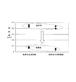
次に、本発明に係る画像形成装置を用いて、従来構成の画像形成装置と比較検証した結果を図4に示す。図4は、画像形成装置の軸方向手前側と奥側において、帯電ロールの軸ずれ量を検証評価した結果を示す図である。 Next, FIG. 4 shows a result of comparison and verification with an image forming apparatus having a conventional configuration using the image forming apparatus according to the present invention. FIG. 4 is a diagram illustrating a result of verification and evaluation of the axial deviation amount of the charging roll on the front side and the rear side in the axial direction of the image forming apparatus.
なお、本発明に係る画像形成装置としては、図2に示される所定の領域Rに帯電ロール用クリーニング部材CLが配置された画像形成装置を用い、従来の画像形成装置としては、図3に示されるような領域R’に帯電ロール用クリーニング部材CL’が配置された画像形成装置を用いて比較検証を行った。 As the image forming apparatus according to the present invention, an image forming apparatus in which the charging roll cleaning member CL is disposed in the predetermined region R shown in FIG. 2 is used. As a conventional image forming apparatus, the image forming apparatus shown in FIG. Comparison verification was performed using an image forming apparatus in which a charging roll cleaning member CL ′ is disposed in such a region R ′.
また、感光体ドラム2の移動に伴う帯電ロール3の変動量としては、軸方向端部における変動量が大きくなるため、静止状態から10秒間駆動後の帯電ロール3の軸方向両端部の軸ずれ量をレーザー変位計(分解能0.1μm、測定範囲±1mm)を用いて測定した。
Further, as the fluctuation amount of the charging
図4から容易に理解されるように、従来構成の画像形成装置においては、軸方向両端部の変動量が、いずれも0.4〜0.5mmであるのに対し、本発明に係る画像形成装置においては、軸方向両端部の変動量が、いずれも0〜0.1mmの範囲に収まっており、従来構成の画像形成装置に比し、大幅に帯電ロール3の位置ずれ(軸ずれ)を防止できることが分かる。
As can be easily understood from FIG. 4, in the image forming apparatus having the conventional configuration, the variation amount at both ends in the axial direction is 0.4 to 0.5 mm, whereas the image forming according to the present invention is performed. In the apparatus, the fluctuation amounts at both ends in the axial direction are within the range of 0 to 0.1 mm, and the positional deviation (axial deviation) of the charging
なお、本実施の形態においては、支持手段として、帯電ロール用クリーニング部材CLを帯電ロール3の所定の周面領域Rに配置したが、装置レイアウト上、帯電ロール用クリーニング部材CLをこのような領域Rに配置できない場合には、例えば、小径のロール状(ピン状)の部材を当該領域Rに帯電ロール3と当接するように配置してもよい。
In this embodiment, the charging roll cleaning member CL is disposed in the predetermined peripheral surface region R of the charging
このように構成した場合でも、構成部材が増加するものの、感光体ドラム2の回転に伴う帯電ロール3の移動を、簡易な構成で直接的に確実に防止することができる。
Even in such a configuration, although the number of components increases, the movement of the charging
1Y−1K:画像形成ユニット、2Y−2K:感光体ドラム、3Y−3K:帯電ロール、4Y−4K:露光装置、5Y−5K:現像装置、6Y−6K:一次転写ロール、7Y−7K:ドラムクリーニング装置、8Y:除電装置、9:中間転写ベルト、10Y−10K:トナーカートリッジ、12:二次転写ロール、14:ベルトクリーニング装置、15:定着装置、17:給紙カセット、18:記録用紙、100:画像形成装置、CL:帯電ロール用クリーニング部材、N:ニップ部、R:周面領域、X:ニップ平面 1Y-1K: image forming unit, 2Y-2K: photosensitive drum, 3Y-3K: charging roll, 4Y-4K: exposure device, 5Y-5K: developing device, 6Y-6K: primary transfer roll, 7Y-7K: drum Cleaning device, 8Y: neutralizing device, 9: intermediate transfer belt, 10Y-10K: toner cartridge, 12: secondary transfer roll, 14: belt cleaning device, 15: fixing device, 17: paper feed cassette, 18: recording paper, 100: image forming apparatus, CL: cleaning member for charging roll, N: nip portion, R: peripheral surface area, X: nip plane
Claims (3)
該像担持体に従動回転して像担持体の表面を所定の電位に帯電する帯電ロールと、
前記帯電ロールの回転方向に沿って、前記像担持体と帯電ロールとのニップ部よりも下流側であって、かつ、前記像担持体の軸線と前記帯電ロールの軸線とから構成される平面に垂直で、前記帯電ロールの軸線を含んだ平面よりも上流側において、前記帯電ロールに接触するように配設された支持手段とを有することを特徴とする画像形成装置。 A rotatable image carrier on which an electrostatic latent image is formed;
A charging roll that rotates following the image carrier to charge the surface of the image carrier to a predetermined potential;
A plane that is downstream of the nip portion between the image carrier and the charging roll along the rotation direction of the charging roll and that is constituted by the axis of the image carrier and the axis of the charging roll. An image forming apparatus comprising: a support unit disposed so as to be in contact with the charging roll at a position upstream of a plane including the axis of the charging roll.
前記帯電ロール用クリーニング部材は、前記支持手段を兼用することを特徴とする請求項1に記載の画像形成装置。 A charging roll cleaning member that contacts the charging roll and cleans its surface;
The image forming apparatus according to claim 1, wherein the charging roll cleaning member also serves as the support unit.
Priority Applications (4)
| Application Number | Priority Date | Filing Date | Title |
|---|---|---|---|
| JP2006036851A JP4844154B2 (en) | 2006-02-14 | 2006-02-14 | Image forming apparatus |
| KR1020060092669A KR100876345B1 (en) | 2006-02-14 | 2006-09-25 | Image forming apparatus |
| US11/527,576 US7577375B2 (en) | 2006-02-14 | 2006-09-27 | Image forming apparatus with support member |
| CNB2006101503018A CN100487597C (en) | 2006-02-14 | 2006-10-18 | Image forming apparatus |
Applications Claiming Priority (1)
| Application Number | Priority Date | Filing Date | Title |
|---|---|---|---|
| JP2006036851A JP4844154B2 (en) | 2006-02-14 | 2006-02-14 | Image forming apparatus |
Publications (2)
| Publication Number | Publication Date |
|---|---|
| JP2007219002A true JP2007219002A (en) | 2007-08-30 |
| JP4844154B2 JP4844154B2 (en) | 2011-12-28 |
Family
ID=38368637
Family Applications (1)
| Application Number | Title | Priority Date | Filing Date |
|---|---|---|---|
| JP2006036851A Expired - Fee Related JP4844154B2 (en) | 2006-02-14 | 2006-02-14 | Image forming apparatus |
Country Status (4)
| Country | Link |
|---|---|
| US (1) | US7577375B2 (en) |
| JP (1) | JP4844154B2 (en) |
| KR (1) | KR100876345B1 (en) |
| CN (1) | CN100487597C (en) |
Citations (5)
| Publication number | Priority date | Publication date | Assignee | Title |
|---|---|---|---|---|
| JPH06236093A (en) * | 1993-02-08 | 1994-08-23 | Konica Corp | Contact charging device |
| JPH07140762A (en) * | 1993-11-19 | 1995-06-02 | Ricoh Co Ltd | Cleaning device for contact charging mechanism |
| JPH0895350A (en) * | 1994-09-28 | 1996-04-12 | Ricoh Co Ltd | Image forming device charging device |
| JP2002091259A (en) * | 2000-09-19 | 2002-03-27 | Fuji Xerox Co Ltd | Image forming device |
| JP2004101978A (en) * | 2002-09-11 | 2004-04-02 | Ricoh Co Ltd | Cleaning device and image forming device |
Family Cites Families (19)
| Publication number | Priority date | Publication date | Assignee | Title |
|---|---|---|---|---|
| JP2847524B2 (en) | 1989-04-14 | 1999-01-20 | キヤノン株式会社 | Charging device |
| JPH05297690A (en) | 1992-04-17 | 1993-11-12 | Canon Inc | Charging device |
| US5619311A (en) * | 1993-05-31 | 1997-04-08 | Ricoh Company, Ltd. | Roller charging apparatus and image forming apparatus using the same |
| JPH07261518A (en) | 1994-03-17 | 1995-10-13 | Ricoh Co Ltd | Charging roller cleaning device |
| NL1003057C2 (en) * | 1996-05-07 | 1997-11-10 | Greefs Wagen Carrosserie | Apparatus and method for supplying, removing and transferring objects, such as fruits. |
| US5927472A (en) * | 1997-10-15 | 1999-07-27 | Eisenmann Corporation | Conveyor transfer unit |
| US6381432B1 (en) * | 1998-12-16 | 2002-04-30 | Brother Kogyo Kabushiki Kaisha | Charging device having a toner remover |
| US6757505B2 (en) * | 2001-01-25 | 2004-06-29 | Ricoh Company, Ltd. | Image forming apparatus and cleaning device therefor |
| US6807390B2 (en) * | 2002-04-12 | 2004-10-19 | Ricoh Company, Ltd. | Image forming apparatus |
| US7234584B2 (en) * | 2002-08-31 | 2007-06-26 | Applied Materials, Inc. | System for transporting substrate carriers |
| US7051870B2 (en) * | 2003-11-26 | 2006-05-30 | Applied Materials, Inc. | Suspension track belt |
| US7477862B2 (en) | 2004-02-09 | 2009-01-13 | Ricoh Company, Ltd. | Charged device, cleaning device, process cartridge, toner, and image-forming device that uses these |
| JP4110128B2 (en) | 2004-04-26 | 2008-07-02 | キヤノン株式会社 | Process cartridge, electrophotographic image forming apparatus and bearing member |
| JP4418336B2 (en) * | 2004-09-28 | 2010-02-17 | 株式会社リコー | Process cartridge and image forming apparatus |
| US7539443B2 (en) * | 2005-06-08 | 2009-05-26 | Seiko Epson Corporation | Charging roller and image forming apparatus |
| US7317883B2 (en) * | 2005-06-27 | 2008-01-08 | Kabushiki Kaisha Toshiba | Color image forming apparatus with at least two stages of image forming units |
| JP5140920B2 (en) * | 2005-11-04 | 2013-02-13 | 富士ゼロックス株式会社 | Image forming apparatus |
| KR100846789B1 (en) * | 2006-06-05 | 2008-07-16 | 삼성전자주식회사 | Charge roller cleaning device and electrophotographic image forming apparatus employing the same |
| JP4957086B2 (en) * | 2006-06-12 | 2012-06-20 | 富士ゼロックス株式会社 | Cleaning device and image forming apparatus |
-
2006
- 2006-02-14 JP JP2006036851A patent/JP4844154B2/en not_active Expired - Fee Related
- 2006-09-25 KR KR1020060092669A patent/KR100876345B1/en active Active
- 2006-09-27 US US11/527,576 patent/US7577375B2/en active Active
- 2006-10-18 CN CNB2006101503018A patent/CN100487597C/en active Active
Patent Citations (5)
| Publication number | Priority date | Publication date | Assignee | Title |
|---|---|---|---|---|
| JPH06236093A (en) * | 1993-02-08 | 1994-08-23 | Konica Corp | Contact charging device |
| JPH07140762A (en) * | 1993-11-19 | 1995-06-02 | Ricoh Co Ltd | Cleaning device for contact charging mechanism |
| JPH0895350A (en) * | 1994-09-28 | 1996-04-12 | Ricoh Co Ltd | Image forming device charging device |
| JP2002091259A (en) * | 2000-09-19 | 2002-03-27 | Fuji Xerox Co Ltd | Image forming device |
| JP2004101978A (en) * | 2002-09-11 | 2004-04-02 | Ricoh Co Ltd | Cleaning device and image forming device |
Also Published As
| Publication number | Publication date |
|---|---|
| CN100487597C (en) | 2009-05-13 |
| KR100876345B1 (en) | 2008-12-29 |
| KR20070082010A (en) | 2007-08-20 |
| CN101021700A (en) | 2007-08-22 |
| US20070189799A1 (en) | 2007-08-16 |
| JP4844154B2 (en) | 2011-12-28 |
| US7577375B2 (en) | 2009-08-18 |
Similar Documents
| Publication | Publication Date | Title |
|---|---|---|
| JP4027287B2 (en) | Image forming apparatus | |
| US12372900B2 (en) | Image forming apparatus | |
| JP4899516B2 (en) | Image forming apparatus | |
| JP4962025B2 (en) | Image forming apparatus | |
| JP2014085633A (en) | Image forming apparatus | |
| JP2021038034A (en) | Belt traveling device, transfer device and image forming device | |
| JP4899517B2 (en) | Image forming apparatus | |
| JP4849146B2 (en) | Image forming apparatus | |
| JP2003215878A (en) | Image forming device | |
| JP4337449B2 (en) | Thermal fixing device | |
| JP2003280409A (en) | Image forming apparatus | |
| JP2011197414A (en) | Image forming apparatus | |
| JP4844154B2 (en) | Image forming apparatus | |
| JP7630983B2 (en) | Image forming device | |
| JP2002148954A (en) | Belt device and image forming device | |
| JP2006171788A (en) | Image forming apparatus | |
| JP2008003449A (en) | Image forming apparatus | |
| JP2008139650A (en) | Developing device and image forming device using this | |
| US7583915B2 (en) | Image forming apparatus and method for producing charging roll | |
| JP2007052302A (en) | Image forming apparatus | |
| JP4492202B2 (en) | Image forming apparatus | |
| JP2009122448A (en) | Paper discharging device and image forming apparatus provided with same | |
| JP2006106667A (en) | Transfer device and image forming apparatus | |
| JP2005037681A (en) | Thermal fixing device | |
| JP2003330341A (en) | Image forming device |
Legal Events
| Date | Code | Title | Description |
|---|---|---|---|
| A621 | Written request for application examination |
Free format text: JAPANESE INTERMEDIATE CODE: A621 Effective date: 20081225 |
|
| A977 | Report on retrieval |
Free format text: JAPANESE INTERMEDIATE CODE: A971007 Effective date: 20110613 |
|
| A131 | Notification of reasons for refusal |
Free format text: JAPANESE INTERMEDIATE CODE: A131 Effective date: 20110621 |
|
| A521 | Request for written amendment filed |
Free format text: JAPANESE INTERMEDIATE CODE: A523 Effective date: 20110818 |
|
| TRDD | Decision of grant or rejection written | ||
| A01 | Written decision to grant a patent or to grant a registration (utility model) |
Free format text: JAPANESE INTERMEDIATE CODE: A01 Effective date: 20110913 |
|
| A01 | Written decision to grant a patent or to grant a registration (utility model) |
Free format text: JAPANESE INTERMEDIATE CODE: A01 |
|
| A61 | First payment of annual fees (during grant procedure) |
Free format text: JAPANESE INTERMEDIATE CODE: A61 Effective date: 20110926 |
|
| FPAY | Renewal fee payment (event date is renewal date of database) |
Free format text: PAYMENT UNTIL: 20141021 Year of fee payment: 3 |
|
| R150 | Certificate of patent or registration of utility model |
Ref document number: 4844154 Country of ref document: JP Free format text: JAPANESE INTERMEDIATE CODE: R150 Free format text: JAPANESE INTERMEDIATE CODE: R150 |
|
| S533 | Written request for registration of change of name |
Free format text: JAPANESE INTERMEDIATE CODE: R313533 |
|
| R350 | Written notification of registration of transfer |
Free format text: JAPANESE INTERMEDIATE CODE: R350 |
|
| LAPS | Cancellation because of no payment of annual fees |