JP2007223003A - Robot arm drive tape wrap device - Google Patents
Robot arm drive tape wrap device Download PDFInfo
- Publication number
- JP2007223003A JP2007223003A JP2006048495A JP2006048495A JP2007223003A JP 2007223003 A JP2007223003 A JP 2007223003A JP 2006048495 A JP2006048495 A JP 2006048495A JP 2006048495 A JP2006048495 A JP 2006048495A JP 2007223003 A JP2007223003 A JP 2007223003A
- Authority
- JP
- Japan
- Prior art keywords
- tape
- holder
- shoe assembly
- shaft
- workpiece
- Prior art date
- Legal status (The legal status is an assumption and is not a legal conclusion. Google has not performed a legal analysis and makes no representation as to the accuracy of the status listed.)
- Granted
Links
Images



Landscapes
- Finish Polishing, Edge Sharpening, And Grinding By Specific Grinding Devices (AREA)
Abstract
【課題】前加工が行われる被加工物を、前加工工程で主軸台と心押台等にセンタリングされ支持された状態で、そのまま、産業用ロボットのアーム先端にカセット型テープラップ装置でテープラップ加工が可能で、別のフイルムラップ装置で加工できる装置を提供。
【解決手段】産業用ロボット60のアーム61先端62に、研磨材被覆テープ 5と、テープ 5の研磨材被覆面を軸物の被加工物表面に接触させ押圧するシュー組立体 2と、シュー組立体 2を支持する一対の開閉アーム15、15と、アーム開閉装置46と、テープ巻出ホルダ 6及びテープ巻取ホルダ 7を一体的に交換可能なカセットとして組付けたテープホルダ一体型カセットシュー組立体11を、取付板12を介してロボット60のアーム61先端62に取付けたリスト62のツール支持面63に取付けた。
【選択図】図1A work piece to be pre-processed is tape-wrapped with a cassette-type tape wrap device at the arm tip of an industrial robot as it is while being centered and supported by a headstock and a tailstock in the pre-processing step. A machine that can be processed and can be processed with a separate film wrap device.
An arm covering tip of an arm of an industrial robot, an abrasive covering tape, a shoe assembly for pressing an abrasive covering surface of the tape against a workpiece surface, and a shoe assembly. Tape holder integrated cassette shoe assembly in which a pair of opening and closing arms 15 and 15 supporting 2, arm opening and closing device 46, tape unwinding holder 6 and tape winding holder 7 are assembled as an integrally replaceable cassette 11 is attached to the tool support surface 63 of the wrist 62 attached to the tip 62 of the arm 61 of the robot 60 via the attachment plate 12.
[Selection] Figure 1
Description
本発明は、比較的非圧縮性の研磨材被覆テープと、該テープの研磨材被覆面を回転される加工面を有する鋼管、自動車部品等の被加工物表面に、接触させ押圧する比較的剛性の面を有するシュー組立体とからなり、研磨材被覆テープを使用して被加工物表面を極めて精密にミクロ仕上げするテープラップ装置に関し、特に産業用ロボットのアーム先端にテープホルダ一体型カセットシュー組立体を搭載したロボットアーム駆動テープラップ装置に関する。 The present invention relates to a relatively incompressible abrasive-coated tape, and a relatively rigid material that contacts and presses the surface of a workpiece such as a steel pipe or automobile part having a processed surface that is rotated. A tape wrap device comprising a shoe assembly having a plurality of surfaces and for microfinishing the surface of a workpiece using an abrasive-coated tape, with a tape holder integrated cassette shoe assembly particularly at the arm tip of an industrial robot The present invention relates to a robot arm drive tape wrap device equipped with a solid body.
従来の比較的非圧縮性の研磨材被覆テープと、該テープ研磨材被覆面を被加工物表面に接触させ押圧する剛性凹面を有する一対のシュー組立体とからなり、研磨材被覆テープを使用して被加工物表面を極めて精密にミクロ仕上げするテープラップ装置としては、例えば特許文献1に開示するものがある。このものは、研磨材被覆テープはポリエステルテープを使用し、シュー組立体の凹面は比較的剛性(剛性表面は90デュロメータAの値を超える硬度を有する)を有しかつ精密に加工されたホーニング砥石材料で形成されたインサートストーンを使用し、治具ボーラーで極めて精密に加工されたストーン円弧面を精密に被加工物表面に転写することで知られている。関節型産業用ロボットとしては、例えば特許文献2には、6軸の自由度をもつ関節型産業用ロボットを開示する。
かかる従来のフイルムラップ装置のシュー組立体の剛性凹面を形成する各ストーンは、被加工物軸径又は軸幅、隣接する各被加工物軸間の間隔に応じて製作され、特定の被加工物軸径又は軸幅、隣接する各被加工物軸間の間隔、のみの加工に限定されているため、被加工物の軸径又は軸幅、軸間の間隔、が違えばそれ専用の極めて大型で場所を取り、高価な、複数の剛性凹面を形成するストーンを有するシュー組立体に交換するための段取り替えが必要であり、更に被加工物の軸径又は軸幅、軸間の間隔が異なる異種被加工物をランダムに加工する場合は、専用の、加工アーム又は加工ステーションを増設する必要があった。ベルト駆動式無段変速機の金属製ベルトの接触するシーブ面を有する部品を含むテーパ表面又は平面、又はクランクシャフトのような軸物の被加工物はいずれも多くの前加工工程があり、いずれも主軸台と心押台にセンタリングされ、支持されて前加工が行われる。しかしながら、従来のテープラップ装置は、例えば特許文献1に開示するように、専用の極めて大型で場所を取るので、産業用ロボットのアーム先端に搭載することはできず、例えば特許文献2に示すような、従来の関節型産業用ロボットでは、産業用ロボットのアーム先端にカセット型テープラップ装置を搭載したものはない。
Each stone forming the rigid concave surface of the shoe assembly of such a conventional film wrap apparatus is manufactured according to the work piece shaft diameter or shaft width, and the interval between the adjacent work piece shafts. Since it is limited to machining only the shaft diameter or shaft width and the distance between adjacent workpiece axes, if the workpiece shaft diameter or shaft width and the distance between the axes are different, it is extremely large It is necessary to change the position of the shoe assembly to replace the shoe assembly having a stone which forms a plurality of rigid concave surfaces. Further, the shaft diameter or the shaft width of the workpiece and the distance between the shafts are different. When processing different kinds of workpieces at random, it was necessary to add a dedicated processing arm or processing station. A tapered surface or flat surface including a part having a sheave surface with which a metal belt of a belt-driven continuously variable transmission contacts, or a workpiece of a shaft object such as a crankshaft, has many pre-processing steps. It is centered on and supported by the headstock and tailstock, and pre-processing is performed. However, as disclosed in, for example, Patent Document 1, the conventional tape wrap device is a dedicated and extremely large space and cannot be mounted on the arm tip of an industrial robot. For example, as disclosed in
本発明の課題は、前加工が行われる被加工物を、前加工工程で例えば主軸台と心押台にセンタリングされ支持された状態で、そのまま、産業用ロボットのアーム先端にカセット型テープラップ装置でテープラップ加工が可能で、別のフイルムラップ装置で加工することなく、フレキシブルに加工できるロボットアーム駆動テープラップ装置を提供することにある。 An object of the present invention is to provide a cassette-type tape wrapping device at the tip of an arm of an industrial robot as it is in a state where a workpiece to be pre-processed is centered and supported by, for example, a headstock and a tailstock in the pre-processing step. It is an object of the present invention to provide a robot arm drive tape wrap device which can be tape-wrapped and can be processed flexibly without using a separate film wrap device.
このため本発明は、産業用ロボットのアーム先端に、比較的非圧縮性の研磨材被覆テープ、該テープの研磨材被覆面を被加工物表面に接触させ押圧する比較的剛性の面を有するシュー組立体、テープ巻出ホルダ及びテープ巻取ホルダを一体的に交換可能なカセットとして組付けたテープホルダ一体型カセットシュー組立体を搭載したことを特徴とするロボットアーム駆動テープラップ装置を提供することによって上記した従来製品の課題を解決した。 For this reason, the present invention provides a shoe having a relatively incompressible abrasive-coated tape at the tip of an arm of an industrial robot, and a relatively rigid surface that contacts and presses the abrasive-coated surface of the tape against the workpiece surface. To provide a robot arm drive tape wrap device equipped with a tape holder-integrated cassette shoe assembly in which an assembly, a tape unwinding holder and a tape winding holder are assembled as an integrally replaceable cassette. The above-mentioned problems of the conventional products have been solved.
かかる構成により、比較的非圧縮性の研磨材被覆テープ、該テープの研磨材被覆面を被加工物表面に接触させ押圧する比較的剛性の面を有するシュー組立体、テープ巻出ホルダ及びテープ巻取ホルダを一体的に交換可能なカセットとして組付けたテープホルダ一体型カセットシュー組立体としたので、組立体本体材料をアルミニウムなどを使用してすることにより、例えば10kg未満まで軽量化でき、産業用ロボットのアーム先端にテープホルダ一体型カセットシュー組立体を搭載できるので、前加工が行われる被加工物を、前加工工程で例えば主軸台と心押台にセンタリングされ支持された状態で、そのまま、産業用ロボットのアーム先端にカセット型テープラップ装置でテープラップ加工が可能で、別のフイルムラップ装置で加工することなく、かつフレキシブルに加工できるロボットアーム駆動テープラップ装置を提供するものとなった。 With this configuration, a relatively incompressible abrasive-coated tape, a shoe assembly having a relatively rigid surface that contacts and presses the abrasive-coated surface of the tape against the workpiece surface, a tape unwinding holder, and a tape winding Since the tape holder integrated cassette shoe assembly is assembled as a cassette that can be replaced as a single unit, the assembly body material can be reduced to, for example, less than 10 kg by using aluminum, etc. Since the cassette shoe assembly integrated with the tape holder can be mounted on the tip of the robot arm, the workpiece to be pre-processed is centered and supported by the headstock and tailstock in the pre-processing step. It is possible to tape wrap at the tip of an industrial robot arm with a cassette-type tape wrap device and not with a separate film wrap device. In addition, a robot arm drive tape wrap device that can be processed flexibly is provided.
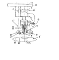
本発明の実施形態の一例を図面を参照して説明する。図1は本発明の第1の実施形態の産業用ロボットのアーム先端にテープホルダ一体型カセットシュー組立体をロボットのアーム先端に取付けた状態を示す、ロボットアーム駆動テープラップ装置全体を示す概略要部斜視図、図2は図1のロボットのアーム先端に取付けたリストのツール支持面に取付けた取付板を拡大して示す要部拡大斜視図、図3は図1のロボットのアーム先端に取付けたテープホルダ一体型カセットシュー組立体を取外した状態で拡大して示す要部拡大斜視図、図4(a)は図3の一体型カセットシュー組立体の内部構造を示す部分を切り欠いた斜視断面、(b)は(a)の裏側の内部構造を示す部分を切り欠いた斜視断面、図5は本発明の第2の実施形態の産業用ロボットのアーム先端に搭載するテープホルダ一体型カセットシュー組立体を取外した状態で拡大して示す要部拡大斜視図、図6は図5のA方向からみた右側面図である。図1に示す産業用ロボット60は、a〜fの6軸の自由度がある。
An example of an embodiment of the present invention will be described with reference to the drawings. FIG. 1 is a schematic diagram showing an entire robot arm driving tape wrap apparatus showing a state in which a tape shoe integrated cassette shoe assembly is attached to an arm tip of an industrial robot according to a first embodiment of the present invention. FIG. 2 is an enlarged perspective view of an essential part showing an enlarged mounting plate attached to a tool support surface of a wrist attached to the arm tip of the robot of FIG. 1, and FIG. 3 is attached to the arm tip of the robot of FIG. FIG. 4A is an enlarged perspective view of a main part shown with the tape holder-integrated cassette shoe assembly removed, and FIG. 4A is a perspective view of the internal structure of the integrated cassette shoe assembly shown in FIG. FIG. 5B is a perspective cross-sectional view in which a portion showing the internal structure on the back side of FIG. 5A is cut out, and FIG. 5 is a tape holder integrated type mounted on the tip of an arm of the industrial robot of the second embodiment of the present invention. Ttoshu set enlarged perspective view showing an enlarged three-dimensional in the detached state, FIG. 6 is a right side view seen from the A direction in FIG. The
本発明の第1の実施形態のロボットアーム駆動テープラップ装置は、図1に示す産業用ロボット60のアーム61先端62に、図2に示す、比較的非圧縮性の研磨材被覆テープ 5と、テープ 5の研磨材被覆面を図示しないクランクシャフトのような軸物の被加工物表面に接触させ押圧する一対の開閉アーム15、15に固定された比較的剛性の凹面17を有するシュー組立体 2と、シュー組立体 2を支持する一対の開閉アーム15、15と、アーム開閉装置46、テープ巻出ホルダ 6及びテープ巻取ホルダ 7を一体的に交換可能なカセットとして組付けたテープホルダ一体型カセットシュー組立体11を、取付板12を介してロボット60のアーム61先端62に取付けたリスト62のツール支持面63に取付けたものである。
The robot arm drive tape wrap device of the first embodiment of the present invention has a relatively incompressible abrasive-coated
かかる構成により、本発明の第1の実施形態のテープホルダ一体型カセットシュー組立体11は、比較的非圧縮性の研磨材被覆テープ 5、テープ 5の研磨材被覆面を被加工物表面に接触させ押圧する比較的剛性の面を有するシュー組立体 2、テープ巻出ホルダ 6及びテープ巻取ホルダ 7を一体的に交換可能なカセットとして組付けたテープホルダ一体型カセットシュー組立体11としたので、組立体本体材料をアルミニウムなどを使用してすることにより、例えば10kg未満まで軽量化でき、産業用ロボットのアーム先端にテープホルダ一体型カセットシュー組立体を搭載できるので、前加工が行われる被加工物を、前加工工程で例えば主軸台と心押台にセンタリングされ支持された状態で、そのまま、産業用ロボットのアーム先端にカセット型テープラップ装置でテープラップ加工が可能で、別のフイルムラップ装置で加工することなく、かつフレキシブルに加工できるロボットアーム駆動テープラップ装置を提供するものとなった。
With such a configuration, the tape holder-integrated
図3、図4に示すように、本発明の第1の実施形態では、テープホルダ一体型カセットシュー組立体11は、アーム開閉用クランプ軸45、及びクランプ軸45に連結されたアーム開閉装置46であるクランプカム37を有し、取付板12に内蔵する図示しない装置により駆動される駆動軸35によって、アーム開閉クランプ軸45が外方に矢印19の方向に(図4(a))押されたとき、クランプカム37が一対のアームの基部47、47を押して、軸42の回りを回動させアーム15、15を閉じるようにされ、クランプ軸45は、駆動軸35が後退するとき、クランプカム37はスプリング26に押され内方に反矢印19方向に引き込まれ、一対のアームの基部47、47が軸42の回りを逆転して、一対のアーム15、15を開くようにされ、かつ同時に、クランプカム37の引き込みに連動して自動的に、テープ巻出ホルダ 6から所定長さのテープ 5を巻き出し方向34(図4(a))に巻き出すとともに、テープ巻取ホルダ 7が所定長さのテープ 5を巻き取り方向32(図4(a))に巻き取るようにされている。4 は凹面17を形成するホーニング砥石材料で形成されたインサートストーン、図3の20はアーム開閉装置46、テープ巻出ホルダ 6及びテープ巻取ホルダ 7を収容したカセット本体である。駆動軸35を駆動する取付板12の装置としては、トリガーに止められたスプリングに押された駆動軸で、ロボットのアーム先端に搭載されたテープホルダ一体型カセットシュー組立体11が、図示しないクランクシャフトのような軸物の被加工物表面を掴む位置に到達したとき、図示しないトリガー駆動装置によってトリガーを外し、スプリングに押されて駆動軸を前進させ一対のアームを開くようにされ、加工終了後は、ロボットのアーム先端の後退に連動して、スプリングに押された駆動軸をもとに戻すようにしてもよく、または電動、流体圧シリンダを使用してもよい。
As shown in FIGS. 3 and 4, in the first embodiment of the present invention, the tape holder integrated
本発明の第1の実施形態のテープホルダ一体型カセットシュー組立体11は図3、図4に示すように、、一対のアーム15、15の基部 47,47は、クランプカム37に(クランプカム37の上側は図3(b)、下側は図3(a))、第1連結ピン31、第1連結ピン31に連結された第1リンク30、第1リンク30に連結された第2連結ピン40を介して駆動的に連結され、基部47、47がクランプカム37と連動するようにされ、テープ巻取ホルダ 7は、図3(b)に示すように、クランプカム37下側と、第2連結ピン90、第2連結ピン90に連結された第2リンク70、第2リンク70に連結された巻取ホルダ軸92及び図示しない逆転防止装置94を介して連結され、テープ巻出ホルダ 6は、テープ巻取ホルダ 7が巻取った所定長さのテープを自動的に巻出ホルダ軸を介して巻出すようにしされている。
As shown in FIGS. 3 and 4, the tape holder-integrated
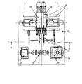
図7は案内台上に配置したヘッドストックとテールストックに支持され、ヘッドストックの駆動装置で回転される、複数の同一径の被加工軸を有するクランクシャフトを含む軸物の被加工物を、X軸方向直動移加工ユニット2台を使用して加工するテープラップ装置のテープラップ加工前の状態を示す概略平面図で、図8は図7のテープラップ装置で被加工物の隣接する被加工軸幅の中央点位置間の距離は同じで、軸幅が僅かに異なるクランクシャフト(a)、(b)の、テープラップ加工中の状態を示す要部部分拡大図である。クランクシャフトでは各同一径を有する複数の被加工軸が2種類のものが多い。図7において、クランクシャフトである軸物の被加工物2'は、案内台20上に配置したヘッドストック18とテールストック19に支持され、ヘッドストック18の駆動モータ21で回転される。図7では、複数の同一径の被加工軸 3の径寸法が2数種類ある被加工軸 3を加工するよう、2数種類のテープホルダ一体型カセットシュー組立体11、11を搭載した、ベッド 20'上に被加工軸2'の軸方向(X軸方向)にX軸移動駆動装置 8、8により移動可能な2台のX軸方向直動移加工ユニット10、10を使用して加工するが、X軸方向直動移加工ユニット10、10の代わりに、図1に示す産業用ロボット60を使用し、アーム61先端62に、1種類のテープホルダ一体型カセットシュー組立体11、11を搭載し、産業用ロボットのティーチングにより、1種類のテープホルダ一体型カセットシュー組立体11により、複数の同一径の被加工軸 3を加工できる。産業用ロボット60は、X軸方向直動移加工ユニット10、10に比べ、6軸自由度を有するので、産業用ロボット60は、設置場所の自由度が高いので、前加工が行われる被加工物を、前加工工程で例えば主軸台と心押台にセンタリングされ支持された状態で、そのまま、産業用ロボットのアーム先端にカセット型テープラップ装置でテープラップ加工が可能で、別のフイルムラップ装置で加工することなく、かつフレキシブルに加工できるテープラップ装置を提供するものとなった。1個の被加工軸 3をテープラップ加工する加工時間は約10秒程度であり、異なる被加工物の軸径又は軸幅、軸間の間隔専用シュー組立体、被加工物を交換するための段取り替え時間が数十分かかることと比較して産業用ロボット使用による加工時間節約効果は極めて大きい。
FIG. 7 shows a workpiece of a shaft including a crankshaft having a plurality of workpiece shafts of the same diameter, which is supported by a headstock and a tailstock arranged on a guide base and rotated by a drive device of the headstock. FIG. 8 is a schematic plan view showing a state before tape wrap processing of a tape wrap apparatus that uses two axially linear transfer processing units, and FIG. 8 is a work that is adjacent to a workpiece by the tape wrap apparatus of FIG. It is the principal part partial enlarged view which shows the state in the tape wrap process of crankshaft (a), (b) from which the distance between the center point positions of axial width is the same, and axial widths differ a little. Many crankshafts have two types of shafts to be machined having the same diameter. In FIG. 7, a
図7において、案内台上に配置したヘッドストックとテールストックに支持され、ヘッドストックの駆動装置で回転される、2種類の複数の同一径の被加工軸 3を有するクランクシャフトを含む被加工物2'において、2数種類のテープホルダ一体型カセットシュー組立体をそれぞれ搭載した2台の産業用ロボット60、60をティーチングにより、それぞれ2種類の複数の同一径の被加工軸 3を加工することができる。代わりに、第1のテープホルダ一体型カセットシュー組立体11を搭載した1台の該産業用ロボット60をティーチングにより、複数の同一径の被加工軸 3を加工した後、第2のテープホルダ一体型カセットシュー組立体11にツールチャンジし、第2の複数の同一径の被加工軸 3を加工してもよい。
In FIG. 7, a workpiece including a crankshaft having a plurality of types of
図7のおいて、案内台上に配置したヘッドストックとテールストックに支持され、ヘッドストックの駆動装置で回転される、同一径であるが軸方向幅が異なる複数の被加工軸 3を有する、クランクシャフトを含む被加工物2'の被加工軸 3において、産業用ロボット60をティーチングにより、第1の幅狭のシュー組立体を有するテープホルダ一体型カセットシュー組立体11により、被加工軸 3のテープラップ加工時に幅狭のシュー組立体50と研磨材被覆テープ51で加工後(図8(b))、回転軸の未加工回転軸表面40があるときは、幅狭のシュー組立体50と研磨材被覆テープ51を被加工物の軸方向に移動させて、回転軸の未加工回転軸表面40を加工するようにした(図8(a))。
In FIG. 7, it has a plurality of processed
本発明の第2の実施形態では、図5、図6に示す比較的非圧縮性の研磨材被覆テープ 5、テープ 5の研磨材被覆面をベルト駆動式無段変速機の金属製ベルトの接触するシーブ面を有する部品 3を含むテーパ表面3'(平面であってもよい)に接触させ押圧する比較的剛性のテーパ表面 4(平面であってもよい)を有するシュー組立体5'、テープ巻出ホルダ6'及びテープ巻取ホルダ7'を一体的に交換可能なカセットとして組付けたテープホルダ一体型カセットシュー組立体 11'を、取付板 12'を介して図1に示すような産業用ロボット60のアーム61先端62に取付けたリスト62のツール支持面63に取付けたものである。かる構成により、本発明の第1の実施形態のロボットアーム駆動テープラップ装置と同様な効果を奏する。
In the second embodiment of the present invention, the relatively incompressible abrasive-
2 、2':シュー組立体、3 、3':被加工物、5 、5':研磨材被覆テープ
6:テープ巻出ホルダ、7:テープ巻取ホルダ、11、11' :一体型カセットシュー組立体、12、12' :取付板、14:背面ガイド部、15:開閉アーム、16:上部ガイド部
17:比較的剛性の凹面、35:駆動軸、37:クランプカム、42:軸、45:クランプ軸
46:アーム開閉装置、47、47:一対のアームの基部、60:機械本体
2, 2 ': Shoe assembly, 3, 3': Work piece, 5, 5 ': Abrasive coating tape 6: Tape unwinding holder, 7: Tape winding holder, 11, 11': Integrated cassette shoe Assembly, 12, 12 ': Mounting plate, 14: Back guide part, 15: Opening / closing arm, 16: Upper guide part
17: relatively rigid concave surface, 35: drive shaft, 37: clamp cam, 42: shaft, 45: clamp shaft
46: Arm opening and closing device, 47, 47: Base of a pair of arms, 60: Machine body
Claims (7)
In a workpiece of a shaft including a crankshaft having a plurality of workpiece shafts of the same diameter, which is supported by a headstock and a tailstock arranged on a guide base and rotated by a headstock driving device, The tape holder integrated cassette having one narrow shoe assembly by teaching the robot, and the tape holder integrated cassette having the narrow shoe assembly during tape lap processing of the shaft to be processed by the tape holder integrated cassette shoe assembly. After processing with the shoe assembly and the abrasive-coated tape, if there is an unprocessed shaft surface of the processed shaft, the tape holder-integrated cassette shoe assembly having the narrow shoe assembly together with the abrasive-coated tape The plurality of machining shafts having the same diameter are machined by moving in the axial direction of the machining shaft to machine the surface of the machining shaft. Robot arm driving the tape wrap system as claimed in claim 3, wherein a.
Priority Applications (1)
| Application Number | Priority Date | Filing Date | Title |
|---|---|---|---|
| JP2006048495A JP4844166B2 (en) | 2006-02-24 | 2006-02-24 | Robot arm drive tape wrap device |
Applications Claiming Priority (1)
| Application Number | Priority Date | Filing Date | Title |
|---|---|---|---|
| JP2006048495A JP4844166B2 (en) | 2006-02-24 | 2006-02-24 | Robot arm drive tape wrap device |
Publications (2)
| Publication Number | Publication Date |
|---|---|
| JP2007223003A true JP2007223003A (en) | 2007-09-06 |
| JP4844166B2 JP4844166B2 (en) | 2011-12-28 |
Family
ID=38545279
Family Applications (1)
| Application Number | Title | Priority Date | Filing Date |
|---|---|---|---|
| JP2006048495A Expired - Fee Related JP4844166B2 (en) | 2006-02-24 | 2006-02-24 | Robot arm drive tape wrap device |
Country Status (1)
| Country | Link |
|---|---|
| JP (1) | JP4844166B2 (en) |
Cited By (1)
| Publication number | Priority date | Publication date | Assignee | Title |
|---|---|---|---|---|
| CN105643402A (en) * | 2016-01-07 | 2016-06-08 | 温州大学 | Stainless steel elbow pipe outer circle polishing system based on industrial manipulator |
Citations (5)
| Publication number | Priority date | Publication date | Assignee | Title |
|---|---|---|---|---|
| JPS6283066A (en) * | 1985-10-07 | 1987-04-16 | Toyota Motor Corp | Automatic water sanding apparatus |
| JPH0775953A (en) * | 1993-09-10 | 1995-03-20 | Toyota Motor Corp | Wrapping device |
| JPH11188597A (en) * | 1997-12-26 | 1999-07-13 | Kansai Giken:Kk | Grinder, its changer mechanism, and supplying receiving mechanism |
| JP2004314200A (en) * | 2003-04-11 | 2004-11-11 | Yaskawa Electric Corp | Automatic polishing equipment |
| JP2006035409A (en) * | 2004-07-26 | 2006-02-09 | Koatec Kk | Grinder with novel function mounted to robot |
-
2006
- 2006-02-24 JP JP2006048495A patent/JP4844166B2/en not_active Expired - Fee Related
Patent Citations (5)
| Publication number | Priority date | Publication date | Assignee | Title |
|---|---|---|---|---|
| JPS6283066A (en) * | 1985-10-07 | 1987-04-16 | Toyota Motor Corp | Automatic water sanding apparatus |
| JPH0775953A (en) * | 1993-09-10 | 1995-03-20 | Toyota Motor Corp | Wrapping device |
| JPH11188597A (en) * | 1997-12-26 | 1999-07-13 | Kansai Giken:Kk | Grinder, its changer mechanism, and supplying receiving mechanism |
| JP2004314200A (en) * | 2003-04-11 | 2004-11-11 | Yaskawa Electric Corp | Automatic polishing equipment |
| JP2006035409A (en) * | 2004-07-26 | 2006-02-09 | Koatec Kk | Grinder with novel function mounted to robot |
Cited By (1)
| Publication number | Priority date | Publication date | Assignee | Title |
|---|---|---|---|---|
| CN105643402A (en) * | 2016-01-07 | 2016-06-08 | 温州大学 | Stainless steel elbow pipe outer circle polishing system based on industrial manipulator |
Also Published As
| Publication number | Publication date |
|---|---|
| JP4844166B2 (en) | 2011-12-28 |
Similar Documents
| Publication | Publication Date | Title |
|---|---|---|
| JP4169739B2 (en) | Method and apparatus for grinding rotationally symmetric mechanical parts | |
| KR101002610B1 (en) | Cylindrical grinding method for producing cemented carbide tools and Cylindrical grinding machine for grinding cylindrical starting bodies in the production of cemented carbide tools | |
| US5896643A (en) | Method of working press die | |
| WO2002064323A1 (en) | Tool compliance device and method | |
| JP2008512255A (en) | How to machine rotating parts | |
| JP4844166B2 (en) | Robot arm drive tape wrap device | |
| JP2005118942A (en) | Work reversing device | |
| JP2005066762A (en) | Carrier robot | |
| JP3108405U (en) | Cylindrical grinding machine for elastic rollers | |
| WO2001087537A1 (en) | Work holding device, milling machine, and long work machining method | |
| JP2005169530A (en) | Grinding machine and grinding method | |
| JPH08118126A (en) | C surface working tool and c surface working method | |
| JP4687285B2 (en) | Polishing processing method and polishing processing apparatus | |
| JP3773715B2 (en) | Centerless grinding machine loading device | |
| JP2000108005A (en) | Shoe assembly of film wrap device | |
| JP4646197B2 (en) | Tape holder integrated cassette shoe assembly | |
| JP4940775B2 (en) | Tape wrap device | |
| JP2007260811A (en) | Tape wrap device | |
| JP2007160452A (en) | Tape wrap device | |
| JP4923609B2 (en) | Cassette type tape wrap device | |
| JP3369461B2 (en) | Inner diameter processing device using micro-finishing film | |
| JP2006218547A (en) | Method for manufacturing ring-shaped member | |
| JP4286437B2 (en) | Industrial robot wrist device | |
| JPH0318086Y2 (en) | ||
| KR101981481B1 (en) | Solenoid body polishing device for automobile transmissions |
Legal Events
| Date | Code | Title | Description |
|---|---|---|---|
| A621 | Written request for application examination |
Free format text: JAPANESE INTERMEDIATE CODE: A621 Effective date: 20090128 |
|
| RD02 | Notification of acceptance of power of attorney |
Free format text: JAPANESE INTERMEDIATE CODE: A7422 Effective date: 20100512 |
|
| A977 | Report on retrieval |
Free format text: JAPANESE INTERMEDIATE CODE: A971007 Effective date: 20110420 |
|
| A131 | Notification of reasons for refusal |
Free format text: JAPANESE INTERMEDIATE CODE: A131 Effective date: 20110510 |
|
| A521 | Request for written amendment filed |
Free format text: JAPANESE INTERMEDIATE CODE: A523 Effective date: 20110708 |
|
| TRDD | Decision of grant or rejection written | ||
| A01 | Written decision to grant a patent or to grant a registration (utility model) |
Free format text: JAPANESE INTERMEDIATE CODE: A01 Effective date: 20110913 |
|
| A01 | Written decision to grant a patent or to grant a registration (utility model) |
Free format text: JAPANESE INTERMEDIATE CODE: A01 |
|
| A61 | First payment of annual fees (during grant procedure) |
Free format text: JAPANESE INTERMEDIATE CODE: A61 Effective date: 20110926 |
|
| FPAY | Renewal fee payment (event date is renewal date of database) |
Free format text: PAYMENT UNTIL: 20141021 Year of fee payment: 3 |
|
| R150 | Certificate of patent or registration of utility model |
Ref document number: 4844166 Country of ref document: JP Free format text: JAPANESE INTERMEDIATE CODE: R150 Free format text: JAPANESE INTERMEDIATE CODE: R150 |
|
| S531 | Written request for registration of change of domicile |
Free format text: JAPANESE INTERMEDIATE CODE: R313531 |
|
| R350 | Written notification of registration of transfer |
Free format text: JAPANESE INTERMEDIATE CODE: R350 |
|
| LAPS | Cancellation because of no payment of annual fees |