JP2007238043A - Support mechanism of suspension line in train line equipment - Google Patents
Support mechanism of suspension line in train line equipment Download PDFInfo
- Publication number
- JP2007238043A JP2007238043A JP2006067150A JP2006067150A JP2007238043A JP 2007238043 A JP2007238043 A JP 2007238043A JP 2006067150 A JP2006067150 A JP 2006067150A JP 2006067150 A JP2006067150 A JP 2006067150A JP 2007238043 A JP2007238043 A JP 2007238043A
- Authority
- JP
- Japan
- Prior art keywords
- suspension
- wire
- line
- sliding member
- guide shaft
- Prior art date
- Legal status (The legal status is an assumption and is not a legal conclusion. Google has not performed a legal analysis and makes no representation as to the accuracy of the status listed.)
- Pending
Links
Images
Landscapes
- Current-Collector Devices For Electrically Propelled Vehicles (AREA)
Abstract
【課題】外気温度の変化による吊架線の伸縮作用に伴い、吊架線のカテナリ曲線が崩れる惧れを防止して、吊架線により吊下げられたトロリー線の直線性を保持することを目的とした電車線装置における吊架線の支持機構を提案する。
【解決手段】電車線に沿って、該電車線を横切るように配置されたビーム30に、これと直交するように、締結バンド2により基部材1を取付け、この基部材1に、懸垂碍子3を介して棒状の案内軸4を、基部材1と平行状に取付け、この案内軸4に、滑車6,6’を有した摺動部材5を摺動可能に取付けて、この摺動部材5に、緩衝手段9を介して吊架線31の保持部片12を連結して成り、外気の温度変化に伴い、吊架線31が伸縮して、その伸縮作用が加わったとき、その伸縮作用に応じて、摺動部材5を案内軸4に沿って水平移動して、吊架線31のビーム30に対する支持点の高さ位置およびトロリー線の直線性を保持する。
【選択図】図1An object of the present invention is to prevent the catenary curve of a suspended wire from collapsing with the expansion and contraction action of the suspended wire due to a change in outside air temperature, and to maintain the linearity of the trolley wire suspended by the suspended wire. A suspension line support mechanism for a train line device is proposed.
A base member 1 is attached by a fastening band 2 to a beam 30 arranged so as to cross the train line so as to be orthogonal to the beam line, and a suspension insulator 3 is attached to the base member 1. A rod-shaped guide shaft 4 is attached in parallel with the base member 1 via the guide member 4, and a sliding member 5 having pulleys 6 and 6 ′ is slidably attached to the guide shaft 4. In addition, the holding part 12 of the suspension wire 31 is connected via the buffering means 9, and when the suspension wire 31 expands and contracts along with the temperature change of the outside air and the expansion / contraction action is applied, Then, the sliding member 5 is moved horizontally along the guide shaft 4 to maintain the height position of the support point with respect to the beam 30 of the suspension wire 31 and the linearity of the trolley wire.
[Selection] Figure 1
Description
本発明は、電車線装置における吊架線の支持機構に関し、特に、カテナリー吊架方式において、温度変化に伴う吊架線の伸縮作用を吊架線の支持点において吸収して、トロリー線の直線性を保持することを目的とした吊架線の支持装置に関する。 The present invention relates to a suspension line support mechanism in a train line device, and in particular, in a catenary suspension system, the extension / contraction action of the suspension line accompanying temperature change is absorbed at the support point of the suspension line to maintain the linearity of the trolley line. The present invention relates to a support device for a suspension wire intended to do.
従来、電車の軌道に沿ってその両側位置に立設した支柱上部間に、前記軌道を横切るように鋼管から成るビームを横架し、このビームに、上端部が締付バンドなどによりビームに固着され、下端部に、懸垂碍子を介して滑車を備えて成る保持部材を取付け、この保持部材の下端部に備えた滑車に、吊架線を走行可能に係合し、このようにして、ビームの相互間に、カテナリー曲線をもって張架された吊架線に対し、曲線引き金具により、前記支柱に保持されたトロリー線を、それが軌道に沿って直線状をなすように、ハンガイヤーにより一定間隔をもって前記吊架線に吊下して成るカテナリー吊架方式における吊架線の支持機構は公知である。
ところが、上記した従来構成の吊架線の支持機構によれば、吊架線は、上端部がビームに固着されて垂下する保持部材の下端部に、滑車を介して、その線条方向に走行可能に支持して成るので、以下に述べるような不都合を有する。 However, according to the suspension wire support mechanism of the conventional configuration described above, the suspension wire can travel in the direction of the line via the pulley at the lower end portion of the holding member whose upper end portion is fixed to the beam and hangs down. Since it is supported, it has the following disadvantages.
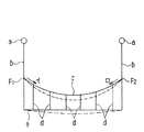
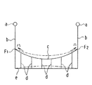
すなわち、図4Aの実線で示すように、ビームaに対し保持部材bによりそれぞれ支持されて、ビームaの相互間でカテナリー曲線をもって張架された吊架線cに、ハンガイヤーdによりトロリー線eが、電車の軌道方向に沿って直線状に張架されている定常状態において、夏期の如く外気温度が高くなって吊架線cが膨張してその線条方向に伸長すると、吊架線cは、保持部材bによる一方の支持点F1においては、図中矢印イ方向に、また、他方の支持点F2においては、図中矢印ロ方向にそれぞれ走行する。 That is, as shown by a solid line in FIG. 4A, a trolley wire e is supported by a hanger d on a suspension line c supported by a holding member b with respect to the beam a and stretched with a catenary curve between the beams a. When the outside air temperature is increased and the suspension line c expands and extends in the direction of the line in a steady state where the suspension line c is stretched linearly along the track direction of the train, the suspension line c becomes the holding member. At one support point F1 due to b, the vehicle travels in the direction of arrow A in the figure, and at the other support point F2, it travels in the direction of arrow B in the figure.
すなわち、吊架線cは、外気温度が高くなったとき、吊架線cの張力が減少して、吊架線cの支持点F1,F2間において、同図仮想線で示すように、実線の状態から下方に大きく弛んで湾曲し、これによってハンガイヤーdを介して直線状に保持されているトロリー線eも亦、同図仮想線で示すように凹状に湾曲して、トロリー線eの直線性が崩れる。 That is, when the outside air temperature becomes high, the tension of the suspension line c decreases from the state of the solid line between the support points F1 and F2 of the suspension line c, as indicated by the phantom line in FIG. The trolley wire e which is greatly slacked downward and curved and thus held in a straight line via the hanger ear d is also bent concavely as shown by the phantom line in the figure, and the linearity of the trolley wire e is broken. .
この現象は、冬期の如く外気温度が低くなって、吊架線cが、その線条方向に短縮した場合も同様である。すなわち、外気温度が低くなって吊架線cがその線条方向に短縮したときは、図4Bで示すように、吊架線cは、保持部材bによる一方の支持点F1においては、図中矢印ハ方向に、また、他方の支持点F2においては、図中矢印ニ方向に走行する。 This phenomenon is the same when the outside air temperature is lowered as in winter and the suspension line c is shortened in the direction of the line. That is, when the outside air temperature is lowered and the suspension line c is shortened in the direction of the line, as shown in FIG. 4B, the suspension line c is at the one support point F1 by the holding member b at the arrow H in the figure. In the direction and at the other support point F2, the vehicle travels in the direction of arrow D in the figure.
このように、吊架線cは、外気温度が低くなったときは、吊架線cの張力が増加して、ビームaに対する吊架線cの支持点F1,F2間において同図仮想線で示すように、実線の状態から押し上げられ、これによってハンガイヤーdを介して直線状に保持されているトロリー線eも亦、同図仮想線で示すように上向き凸状に湾曲し、この場合もトロリー線eの直線性が崩れる。 In this way, when the outside air temperature is lowered, the tension of the suspension line c increases as the tension of the suspension line c increases, and the phantom line between the support points F1 and F2 of the suspension line c with respect to the beam a is shown by the phantom line in FIG. The trolley line e pushed up from the state of the solid line and held in a straight line via the hanger d is also bent upwardly as shown by the virtual line in FIG. Linearity is broken.
その結果、電車の軌道に沿って直線状に張架された吊架線c及びトロリー線eが、温度変化に伴う張力の変動により、その直線性は失われ、この状態でトロリー線eにパンタグラフが進入すると、架線振動が増大して離線とアークが生じトロリー線eやパンタグラフの摺板の消耗を促進し、それによる電車線の断線事故を誘発するという惧れがあった。 As a result, the suspension line c and the trolley line e stretched in a straight line along the tram of the train lose their linearity due to the fluctuation of the tension accompanying the temperature change, and in this state the pantograph appears on the trolley line e. When approaching, there is a fear that the overhead line vibration will increase, causing a disconnection and an arc to promote the consumption of the trolley line e and the pantograph sliding plate, thereby inducing an accidental disconnection of the train line.
特に、外気温度が低い場合は、張力が増大して、トロリー線がつり上がるため、集電上要求される等高線がくずれ、パンタグラフの跳躍が甚だしくなり、運転に支障をきたす惧れがある。 In particular, when the outside air temperature is low, the tension increases and the trolley wire is lifted, so that the contour line required for current collection is broken, the jump of the pantograph becomes serious, and the operation may be hindered.
そこで、本発明は、上記した従来の不都合を解消するために、電車線に沿って該電車線を横切るように配置したビームに対し、これと直交するように取り付けた基部材と、この基部材に対し懸垂碍子を介して、取り付けられてビームと直交する方向に伸びる案内軸と、この案内軸に対し、摺動可能に設けられた摺動部材とから構成され、この摺動部材に、トロリー線を吊下した吊架線の支持部を連結したことを特徴とするものである。 Therefore, in order to eliminate the above-described conventional disadvantages, the present invention provides a base member that is mounted so as to be orthogonal to a beam arranged so as to cross the train line along the train line, and the base member. The guide shaft is attached via a suspension insulator and extends in a direction orthogonal to the beam, and a sliding member provided so as to be slidable with respect to the guide shaft. The support part of the suspension line which suspended the line was connected.
上記において、好ましくは、摺動部材が、その摺動方向における前後位置に、案内軸をその上下方向からそれぞれ挟持するように配置された複数の滑車を備えて成り、この摺動部材の摺動方向における中間位置に、吊架線の支持部を連結したものである。 In the above, preferably, the sliding member comprises a plurality of pulleys arranged so as to sandwich the guide shaft from the vertical direction at the front and rear positions in the sliding direction. The support part of a suspended wire is connected to the intermediate position in the direction.
さらにまた、本願発明は、上記において、案内軸の両端部に、摺動部材の摺動を制限するストッパーを設け、かつ摺動部材と、これに取り付けられる吊架線の支持部との間に、吊架線の支持部に作用する負荷を吸収する緩衝手段を設けて成るものである。 Furthermore, in the present invention, in the above, at both ends of the guide shaft, a stopper for restricting sliding of the sliding member is provided, and between the sliding member and the support portion of the suspension wire attached thereto, A buffer means for absorbing a load acting on the support portion of the suspension wire is provided.
本願発明は、叙上のように構成されているので、外気温度が変化して、吊架線が伸長乃至短縮するいずれの場合でも、その伸長乃至短縮の度合に応じてビームに対する吊架線の支持部を、常に摺動部材により水平移動させる構成であるので、該吊架線の支持部の位置が、従来のように温度変化により高さ方向に変動する惧れなく、従って、トロリー線の直線性を保持することができるという利点を有する。 Since the present invention is configured as described above, in any case where the outside air temperature changes and the suspension line extends or shortens, the suspension line support portion for the beam according to the extent of the extension or shortening. The position of the support portion of the suspension wire is not likely to fluctuate in the height direction due to a temperature change as in the prior art, and therefore the linearity of the trolley wire is reduced. It has the advantage that it can be retained.
特に、請求項2記載の発明によれば、吊架線の支持部に、吊架線の温度変化に伴う伸長乃至短縮作用により、摺動部材を左右方向に索引する負荷が作用したとき、これによって案内軸に対する摺動部材の浮き上がり現象が生じるが、摺動部材の摺動方向の前後位置に滑車を備えて成るので、この浮き上がり現象を防止することができるので、摺動部材の案内軸に対する摺動作用が円滑となる利点を有する。 In particular, according to the second aspect of the present invention, when a load for indexing the sliding member in the left-right direction is applied to the support portion of the suspension wire due to the extending or shortening operation accompanying the temperature change of the suspension wire, the guide is thereby performed. Although the sliding member is lifted with respect to the shaft, since the pulley is provided at the front and rear positions in the sliding direction of the sliding member, this lifting phenomenon can be prevented. There is an advantage that the use is smooth.
さらにまた、請求項3記載の発明によれば、摺動部材に作用する摺動負荷を緩衝手段により吸収するので、摺動部材と吊架線の支持部との一体性が保持されると共に、吊架線の温度変化に伴う切断現象を防止することができるという利点を有する。 Furthermore, according to the third aspect of the present invention, since the sliding load acting on the sliding member is absorbed by the buffer means, the integrity of the sliding member and the support portion of the suspension wire is maintained, and the suspension is suspended. It has the advantage that the cutting phenomenon accompanying the temperature change of an overhead wire can be prevented.
以下図面にもとづいて、本発明を実施するための最良の形態について詳述する。
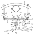
図1は電車線に沿って軌道の左右側部に立設した支柱の上部間に、電車線を横断するように渡架した鋼管から成るビーム30に、本発明の支持機構を備えた場合の正面図を示しており、1はアーチ状に湾曲した長尺の鋼管から成る基部材で、その長手方向の中央位置の下面が、締結バンド2を介して前記ビーム30の上面に直交状に固着してある。
Hereinafter, the best mode for carrying out the present invention will be described in detail with reference to the drawings.
FIG. 1 shows a case in which a
前記基部材1の両端部下面には、懸垂碍子3を介して、棒状の案内軸4の両端部が、基部材1と平行状に取付けてあり、この案内軸4には、該案内軸4の長手方向に沿って摺動する摺動部材5が取付けてある。
Both end portions of a rod-
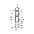
この摺動部材5は、摺動方向の前後位置に、前記案内軸4を、その上方から挟持する二個の滑車6を、また該滑車6,6の中間位置の下方には、前記案内軸4を、その下方から挟持する一個の滑車6’を、それらが正三角形の各頂点に位置するように、図2で示すように、正面方向で対峙する一対の側板7,7間に回転可能に配して成り、また、案内軸4の両端には、摺動部材5と衝合して、その摺動範囲を制限するストッパー8が設けてある。
The sliding
前記摺動部材5の下部には、緩衝手段9を介して、吊架線31の支持部が連結される。
A support portion for the
前記緩衝手段9は、図2で示すように、前記摺動部材5を構成する正面方向で対峙する一対の側板7,7を、それぞれ下方に対称に延長して形成した袖板10,10と、上端が前記袖板10,10の上部にピン11を介して傾動自在に支承されて下方に延び、その下端に吊架線31の支持部を保持する保持部片12を有した連結部片13,13と、正面で対峙する前記袖板10,10の間に保持され、内部に渦巻バネ(図示せず)を収納したスリーブ14とから成り、前記渦巻バネは、その一端がスリーブ14内に固定されると共に、その他端がスリーブ14から外部に導出され、その導出部15の自由端が、前記保持部片12の位置に係止されており、このようにして、前記ピン11と保持部片12との間に、渦巻バネによる圧縮力を付勢する。
As shown in FIG. 2, the buffer means 9 includes
このように、ピン11と保持部片12との間に、渦巻バネによる圧縮力を付勢することにより、連結部片13,13の垂直状態および、摺動部材5と緩衝手段9との一体性が保持される。
In this way, by urging the compression force by the spiral spring between the
しかして、図1において、外気温度が高くなって、吊架線31の張力が減少し、該吊架線31が図中矢印ホの方向に伸長すると、その伸長作用により、緩衝手段9と摺動部材5とが一体となって、摺動部材5は案内軸4に沿って図中左方向に水平移動する。
Thus, in FIG. 1, when the outside air temperature becomes high, the tension of the
また、図1において、外気温度が低くなって、吊架線31の張力が増加して、該吊架線31が図中矢印ヘの方向に移動するときは、その短縮作用により、緩衝手段9と摺動部材5とが一体となって、摺動部材5は案内軸4に沿って図中右方向に水平移動する。
Further, in FIG. 1, when the outside air temperature is lowered and the tension of the
この水平移動の作用は、吊架線31のビーム30に対する全ての支持点位置において行われる。
This horizontal movement is performed at all support point positions of the
すなわち、外気温度の変化に伴って、吊架線31が線条方向に伸長乃至短縮するいずれの場合でも、ピン11と保持部片12との間に付勢された渦巻バネによる圧縮力により、摺動部材5の摺動抵抗(負荷)は吸収され、その結果、摺動部材5は吊架線31の支持部と一体となって、案内軸4に沿って水平移動し、吊架線31の高さ位置は、吊架線31の温度変化により変動する惧れはなく、従って、吊架線31によるカテナリー曲線は崩れることなく、トロリー線eの直線性を維持することができる。
That is, in any case where the
また、図1において、摺動部材5が、緩衝手段9とが一体となって図中実線の位置から図中右方向に水平移動し、摺動部材5が、ストッパー8に衝合してその摺動範囲の極限位置に達した状態から、さらに吊架線31に矢印ヘ方向に強い負荷が作用したときは、渦巻バネの圧縮付勢力による連結部片13の垂直状態の保持が不能になって、同図仮想線で示すように、渦巻バネの付勢力に抗して連結部片13は、ピン11を支点として図中反時計方向に傾動して、吊架線31の支持部に作用する大きな負荷を吸収して、吊架線31の破断を防止することができる。
Further, in FIG. 1, the sliding
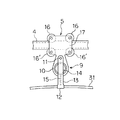
図3は、摺動部材5および緩衝手段9の他の実施例図を示しており、さきの実施例と相違するところは、摺動部材5において、案内軸4を、その摺動方向の前後位置で、その上下方向からそれぞれ挟持する四個の滑車6,6,6’,6’を使用して、これらを方形状の側板の各隅部に配して構成した点にあり、その作用は基本的にさきの実施例と相違するところはない。
FIG. 3 shows another embodiment of the sliding
1 基部材
3 懸垂碍子
4 案内軸
5 摺動部材
6,6’ 滑車
7 側板
8 ストッパー
9 緩衝手段
10 袖板
11 ピン
12 保持部片
13 連結部片
14 スリーブ
DESCRIPTION OF SYMBOLS 1 Base member 3
Claims (3)
Priority Applications (1)
| Application Number | Priority Date | Filing Date | Title |
|---|---|---|---|
| JP2006067150A JP2007238043A (en) | 2006-03-13 | 2006-03-13 | Support mechanism of suspension line in train line equipment |
Applications Claiming Priority (1)
| Application Number | Priority Date | Filing Date | Title |
|---|---|---|---|
| JP2006067150A JP2007238043A (en) | 2006-03-13 | 2006-03-13 | Support mechanism of suspension line in train line equipment |
Publications (1)
| Publication Number | Publication Date |
|---|---|
| JP2007238043A true JP2007238043A (en) | 2007-09-20 |
Family
ID=38583978
Family Applications (1)
| Application Number | Title | Priority Date | Filing Date |
|---|---|---|---|
| JP2006067150A Pending JP2007238043A (en) | 2006-03-13 | 2006-03-13 | Support mechanism of suspension line in train line equipment |
Country Status (1)
| Country | Link |
|---|---|
| JP (1) | JP2007238043A (en) |
Cited By (8)
| Publication number | Priority date | Publication date | Assignee | Title |
|---|---|---|---|---|
| RU2623416C1 (en) * | 2016-04-12 | 2017-06-26 | Николай Васильевич Костриков | Suspension of compensated carrier cable to portal structure girder |
| RU2627906C2 (en) * | 2016-09-27 | 2017-08-14 | Александр Васильевич Дегтярев | Method of suspending powered electrolines of vehicles by self-centering system with electrically insulating rollers |
| RU2627910C2 (en) * | 2016-09-06 | 2017-08-14 | Александр Васильевич Дегтярев | Method of suspending powered electrolines of vehicles by self-centering system with electrically insulating rollers |
| RU2627903C2 (en) * | 2016-10-28 | 2017-08-14 | Александр Васильевич Дегтярев | Method of suspending supply lines of vehicles with use of universal self-centering system having three rollers on internal basis |
| RU2627908C2 (en) * | 2016-09-07 | 2017-08-14 | Александр Васильевич Дегтярев | Method of suspending supply lines of vehicles between line supports on railway track |
| RU2632364C2 (en) * | 2016-09-08 | 2017-10-04 | Александр Васильевич Дегтярев | Method of transport power lines stringing among lines poles on railway track |
| RU2636434C2 (en) * | 2016-10-28 | 2017-11-23 | Александр Васильевич Дегтярев | Method of stringing of transport power means between supports on railway |
| RU2861447C1 (en) * | 2025-08-26 | 2026-05-05 | Открытое Акционерное Общество "Российские Железные Дороги" | Device for fixing rod insulator |
Citations (5)
| Publication number | Priority date | Publication date | Assignee | Title |
|---|---|---|---|---|
| JPS5572425A (en) * | 1978-11-25 | 1980-05-31 | Sanwa Tekki Corp | Suspension wire movable support device |
| JPS58142144A (en) * | 1982-02-19 | 1983-08-23 | Toshiba Corp | Combustion equipment for room heating |
| JPS58173535A (en) * | 1982-04-06 | 1983-10-12 | 三菱電機株式会社 | Sleepiness detecting apparatus |
| JP2000085415A (en) * | 1998-09-17 | 2000-03-28 | Shintookoo:Kk | Trolley wire suspension device |
| JP2000262753A (en) * | 1999-03-12 | 2000-09-26 | Sanei:Kk | Ropeway with automatic sliding tool return mechanism |
-
2006
- 2006-03-13 JP JP2006067150A patent/JP2007238043A/en active Pending
Patent Citations (5)
| Publication number | Priority date | Publication date | Assignee | Title |
|---|---|---|---|---|
| JPS5572425A (en) * | 1978-11-25 | 1980-05-31 | Sanwa Tekki Corp | Suspension wire movable support device |
| JPS58142144A (en) * | 1982-02-19 | 1983-08-23 | Toshiba Corp | Combustion equipment for room heating |
| JPS58173535A (en) * | 1982-04-06 | 1983-10-12 | 三菱電機株式会社 | Sleepiness detecting apparatus |
| JP2000085415A (en) * | 1998-09-17 | 2000-03-28 | Shintookoo:Kk | Trolley wire suspension device |
| JP2000262753A (en) * | 1999-03-12 | 2000-09-26 | Sanei:Kk | Ropeway with automatic sliding tool return mechanism |
Cited By (8)
| Publication number | Priority date | Publication date | Assignee | Title |
|---|---|---|---|---|
| RU2623416C1 (en) * | 2016-04-12 | 2017-06-26 | Николай Васильевич Костриков | Suspension of compensated carrier cable to portal structure girder |
| RU2627910C2 (en) * | 2016-09-06 | 2017-08-14 | Александр Васильевич Дегтярев | Method of suspending powered electrolines of vehicles by self-centering system with electrically insulating rollers |
| RU2627908C2 (en) * | 2016-09-07 | 2017-08-14 | Александр Васильевич Дегтярев | Method of suspending supply lines of vehicles between line supports on railway track |
| RU2632364C2 (en) * | 2016-09-08 | 2017-10-04 | Александр Васильевич Дегтярев | Method of transport power lines stringing among lines poles on railway track |
| RU2627906C2 (en) * | 2016-09-27 | 2017-08-14 | Александр Васильевич Дегтярев | Method of suspending powered electrolines of vehicles by self-centering system with electrically insulating rollers |
| RU2627903C2 (en) * | 2016-10-28 | 2017-08-14 | Александр Васильевич Дегтярев | Method of suspending supply lines of vehicles with use of universal self-centering system having three rollers on internal basis |
| RU2636434C2 (en) * | 2016-10-28 | 2017-11-23 | Александр Васильевич Дегтярев | Method of stringing of transport power means between supports on railway |
| RU2861447C1 (en) * | 2025-08-26 | 2026-05-05 | Открытое Акционерное Общество "Российские Железные Дороги" | Device for fixing rod insulator |
Similar Documents
| Publication | Publication Date | Title |
|---|---|---|
| JP2009079395A (en) | Method for erecting main girder of bridge by erection beam, and lateral transfer mechanism of erection beam | |
| CN111422213A (en) | Suspension structure for air-rail bogies and air-rail vehicles | |
| CN103660842A (en) | Leaf spring balanced suspension mechanism and engineering vehicle having same | |
| KR101625488B1 (en) | one-piece girder type expanded footbridge and vibration reducing structure of the same | |
| TWI295243B (en) | Current collector shoe device | |
| CN208395652U (en) | A kind of highway bridge support | |
| WO2014175290A1 (en) | Seat suspension | |
| CN101321916B (en) | Curved Beams for Magnetic Levitation Tracks | |
| CN219827578U (en) | Shock absorbing device for boarding bridge | |
| JP4271004B2 (en) | Pantograph device | |
| JP2008232437A (en) | Direct acting type rolling abutment | |
| JP3769266B2 (en) | Section insulator | |
| CN108974198A (en) | A shock-absorbing device for a somatosensory balance car seat | |
| CN111455743B (en) | Layout method of linear adjustment and vibration damping structure for cable-rail overhead rail structure | |
| JP2016211238A (en) | Girder deflection reduction device | |
| CN208151773U (en) | A kind of cross-saddle single-track traffic radial type two-orbit beam | |
| CN213565869U (en) | Suspension device of suspension type air rail train | |
| JP6901325B2 (en) | Vibration absorber for overhead wire | |
| CN112779851B (en) | A long-span conventional high-speed maglev bridge split structure | |
| US2962981A (en) | Railroad vehicle suspension | |
| JPS61218443A (en) | Spring device for pull-off fitting | |
| CN219260596U (en) | Anti-slip track sleeper beam | |
| JP2005205927A (en) | Levelling suspension device for railway vehicle | |
| JP2022094987A (en) | Rail brake device for railway vehicle | |
| JPH04172901A (en) | Double stage link type pantograph inclining system for rolling stock |
Legal Events
| Date | Code | Title | Description |
|---|---|---|---|
| A621 | Written request for application examination |
Free format text: JAPANESE INTERMEDIATE CODE: A621 Effective date: 20090303 |
|
| A977 | Report on retrieval |
Free format text: JAPANESE INTERMEDIATE CODE: A971007 Effective date: 20110303 |
|
| A02 | Decision of refusal |
Effective date: 20111024 Free format text: JAPANESE INTERMEDIATE CODE: A02 |