JP2007242569A - Protection element deterioration / operation display device - Google Patents
Protection element deterioration / operation display device Download PDFInfo
- Publication number
- JP2007242569A JP2007242569A JP2006066927A JP2006066927A JP2007242569A JP 2007242569 A JP2007242569 A JP 2007242569A JP 2006066927 A JP2006066927 A JP 2006066927A JP 2006066927 A JP2006066927 A JP 2006066927A JP 2007242569 A JP2007242569 A JP 2007242569A
- Authority
- JP
- Japan
- Prior art keywords
- heat
- deterioration
- protection element
- display device
- shrinkable material
- Prior art date
- Legal status (The legal status is an assumption and is not a legal conclusion. Google has not performed a legal analysis and makes no representation as to the accuracy of the status listed.)
- Granted
Links
- 230000006866 deterioration Effects 0.000 title claims abstract description 22
- 239000002654 heat shrinkable material Substances 0.000 claims abstract description 27
- 239000012769 display material Substances 0.000 claims abstract description 15
- 230000001681 protective effect Effects 0.000 claims abstract description 11
- 230000015556 catabolic process Effects 0.000 claims description 6
- 239000004020 conductor Substances 0.000 claims description 5
- 238000006731 degradation reaction Methods 0.000 claims description 5
- 239000003086 colorant Substances 0.000 claims description 2
- 239000000463 material Substances 0.000 description 8
- 230000001012 protector Effects 0.000 description 7
- 238000007796 conventional method Methods 0.000 description 4
- 238000010586 diagram Methods 0.000 description 4
- 229910000679 solder Inorganic materials 0.000 description 3
- RNFJDJUURJAICM-UHFFFAOYSA-N 2,2,4,4,6,6-hexaphenoxy-1,3,5-triaza-2$l^{5},4$l^{5},6$l^{5}-triphosphacyclohexa-1,3,5-triene Chemical compound N=1P(OC=2C=CC=CC=2)(OC=2C=CC=CC=2)=NP(OC=2C=CC=CC=2)(OC=2C=CC=CC=2)=NP=1(OC=1C=CC=CC=1)OC1=CC=CC=C1 RNFJDJUURJAICM-UHFFFAOYSA-N 0.000 description 2
- 239000003063 flame retardant Substances 0.000 description 2
- 238000012423 maintenance Methods 0.000 description 2
- 239000000155 melt Substances 0.000 description 2
- 238000000034 method Methods 0.000 description 2
- 238000005476 soldering Methods 0.000 description 2
- 238000001514 detection method Methods 0.000 description 1
- 239000011810 insulating material Substances 0.000 description 1
- 239000002184 metal Substances 0.000 description 1
- 229920003023 plastic Polymers 0.000 description 1
- 239000004033 plastic Substances 0.000 description 1
- 229920000098 polyolefin Polymers 0.000 description 1
- 229920000915 polyvinyl chloride Polymers 0.000 description 1
- 239000004800 polyvinyl chloride Substances 0.000 description 1
- 239000002470 thermal conductor Substances 0.000 description 1
Images


Landscapes
- Fuses (AREA)
- Thermistors And Varistors (AREA)
Abstract
【課題】極めて簡単な構成により、保護素子の劣化や動作状態を確実に表示可能とし、低コストにて製造可能とした劣化・動作表示装置を提供する。
【解決手段】保護素子の劣化または動作を視覚的に表示するようにしたバリスタ等の保護素子の劣化・動作表示装置に関する。劣化または動作した保護素子21が発生する熱が伝導される熱伝導板1と、この熱伝導板1の熱により収縮、退避する熱収縮材2と、この熱収縮材2収縮、退避時に、窓部1dを介して外部から目視される表示材3と、を備え、この表示材3により、保護素子21の劣化または動作を表示する。
【選択図】図1The present invention provides a deterioration / operation display device capable of reliably displaying deterioration and an operation state of a protection element with an extremely simple configuration and capable of being manufactured at low cost.
The present invention relates to a deterioration / operation display device for a protection element such as a varistor that visually displays the deterioration or operation of the protection element. The heat conduction plate 1 through which heat generated by the deteriorated or operated protection element 21 is conducted, the heat shrinkable material 2 that shrinks and retreats by the heat of the heat conduction plate 1, and the heat shrinkable material 2 contracts and retreats when the window is opened. A display material 3 that is viewed from the outside through the part 1d, and the display material 3 displays the deterioration or operation of the protective element 21.
[Selection] Figure 1
Description
本発明は、雷等の過電圧、過電流から各種機器を保護するための保護素子の劣化・動作表示装置に関し、詳しくは、バリスタ、アレスタ等の保護素子が発生する熱を検出して劣化状態、動作状態を表示可能とした表示装置に関するものである。 The present invention relates to a deterioration / operation display device of a protection element for protecting various devices from overvoltage and overcurrent such as lightning, and more specifically, by detecting heat generated by a protection element such as a varistor or arrester, The present invention relates to a display device capable of displaying an operation state.
この種の表示装置の従来技術として、例えば特許文献1,2に記載されているように、避雷素子に流れる漏洩電流を検出して避雷素子の劣化を表示する表示装置が知られている。
また、特許文献3に記載されているように、避雷器の劣化時や短絡破壊時に導電性プラスチックを溶断させてスプリングにより表示部を動作させる切り離し装置も公知となっており、更には、温度ヒューズやハンダを溶融させてスプリングにより表示部を動作させる劣化表示装置も既に知られている。
As a conventional technique of this type of display device, for example, as described in
Further, as described in
特許文献1,2に記載された従来技術では、漏洩電流を検出して表示部を動作させるための回路構成が複雑であり、コストが高くなるという問題がある。
また、特許文献3に記載された従来技術や温度ヒューズ、ハンダ等を用いる従来技術では、表示部を駆動するためのスプリング等が構造の複雑化や大型化の原因になり、特に、ハンダを溶融させる方式では、ハンダ付け作業に熟練が必要であると共に、個人差によって検出精度が安定せず、信頼性が低い等の問題があった。
In the conventional techniques described in
Further, in the conventional technique described in
そこで本発明の解決課題は、極めて簡単な構成により、保護素子の劣化や動作状態を確実に表示可能とし、低コストにて製造可能とした劣化・動作表示装置を提供することにある。 SUMMARY OF THE INVENTION An object of the present invention is to provide a deterioration / operation display device that can reliably display the deterioration and operation state of a protective element with a very simple configuration and can be manufactured at low cost.
上記課題を解決するため、請求項1に記載した発明は、保護素子の劣化または動作を視覚的に表示するようにした保護素子の劣化・動作表示装置において、
劣化または動作した前記保護素子が発生する熱が伝導される熱伝導体と、
この熱伝導体の熱により収縮、退避する熱収縮材と、
この熱収縮材の収縮、退避時に、窓部を介して外部から目視される表示材と、を備え、
この表示材により、前記保護素子の劣化または動作を表示するものである。
In order to solve the above problem, the invention described in
A heat conductor through which heat generated by the deteriorated or operated protection element is conducted; and
A heat-shrinkable material that shrinks and retracts due to the heat of the heat conductor;
When the heat shrinkable material is shrunk and retracted, the display material is visually observed from the outside through the window portion, and
By this display material, the deterioration or operation of the protection element is displayed.
請求項2に記載した発明は、請求項1において、
平常時には、前記窓部を介して外部から前記熱収縮材が目視されるものである。
The invention described in
In normal times, the heat shrinkable material is visually observed from the outside through the window portion.
請求項3に記載した発明は、請求項2において、
外部から目視される前記熱収縮材及び前記表示材の表面を、異なる色でそれぞれ着色したものである。
The invention described in
The heat-shrinkable material and the surface of the display material visually observed from the outside are colored with different colors.
本発明によれば、バリスタ、アレスタ等の保護素子の劣化や短絡破壊によってその温度が上昇すると、熱収縮材が収縮して退避し、窓部を介して表示材を外部から目視できるようになる。これにより、劣化または動作した保護素子や保安器を外部から容易に確認することが可能になる。
本発明では、従来技術のように漏洩電流の増加を電気的に検出する方法によらないので、複雑な電気回路も不要である。また、表示部を駆動するためのスプリング等も不要であり、構造上、極めて簡単であると共に、従来のハンダ付け作業における熟練も要求されないので、本発明が実装される保安器の小型化、低コスト化に寄与する等の利点がある。
According to the present invention, when the temperature rises due to deterioration or short-circuit breakdown of protective elements such as varistors and arresters, the heat-shrinkable material shrinks and retracts, and the display material can be visually observed from the outside through the window portion. . Thereby, it becomes possible to easily check the deteriorated or operated protection element or protector from the outside.
Since the present invention does not depend on a method of electrically detecting an increase in leakage current unlike the prior art, a complicated electric circuit is also unnecessary. In addition, a spring for driving the display unit is not necessary, and it is extremely simple in structure and does not require skill in conventional soldering work. There are advantages such as contributing to cost reduction.
以下、図に沿って本発明の実施形態を説明する。
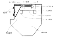
図1は本発明の実施形態を示す構成図であり、1は平板状の金属からなる熱伝導板である。この熱伝導板1の上端部には、熱によって収縮する材料(例えば、難燃性ポリオレフィンや難燃性ポリ塩化ビニルなど)からなる環状の熱収縮材2が配置されている。後述するように、熱伝導板1は保護素子から発生した熱を下記の熱収縮材2に伝導させる作用を果たせば良いから、熱伝導体としては、板状材に限らず棒状材やブロック状材であっても良い。
Hereinafter, embodiments of the present invention will be described with reference to the drawings.
FIG. 1 is a block diagram showing an embodiment of the present invention, and 1 is a heat conduction plate made of a flat metal. An annular heat-
熱伝導板1の上部左側には、柵状の保持部1aが形成され、また、上端部には一対のガイド部1b,1cが形成されており、環状の熱収縮材2は、保持部1aに千鳥状に掛け渡されてガイド部1b,1cの間で二重になった状態で配置されている。図示されていないが、ガイド部1b,1cの内部には、熱収縮材2を図示するような位置に案内して保持するためのリブ等が設けられている。
A fence-like holding portion 1a is formed on the upper left side of the
更に、ガイド部1b,1cの相互間には窓部1dが形成されており、熱伝導板1の温度が低い平常時には、窓部1d内に熱収縮材2が存在し、外部からは窓部1dを介して熱収縮材2の表面が目視されるようになっている。このとき、ガイド部1cの背後にある熱収縮材2の折り返し部分はフリーな状態(熱収縮材2の収縮によって自身が移動可能な状態)にある。
Further, a window portion 1d is formed between the guide portions 1b and 1c. When the temperature of the
一方、ガイド部1b,1cより奥まった位置の熱伝導板1の表面には、一対の支持部1e,1fが設けられており、これらの支持部1e,1fの間には、前記窓部1d側の表面が例えば赤色に着色された表示材3が張架されている。
上記のように構成することにより、熱伝導板1の温度が低い平常時には、外部から窓部1dを介して熱収縮材2の表面が目視され、熱伝導板1が加熱されてその温度が上昇した場合には、図2に示すように熱収縮材2が保持部1a方向に収縮して窓部1dから退避し、外部からは窓部1dを介して表示材3の表面が目視されるようになっている。
なお、平常時に窓部1dを介して目視される熱収縮材2の表面は、表示材3の表面とは異なる色、例えば白色に着色されている。
On the other hand, a pair of support portions 1e and 1f are provided on the surface of the
By configuring as described above, during normal times when the temperature of the
Note that the surface of the heat-
次に、図3は本実施形態にかかる劣化・動作表示装置を保安器に実装した状態の内部構造を示している。実際には、図示されていないカバーがこの上に装着されて保安器の全体が構成されるものであり、カバーに別途形成される窓部を介して前記窓部1dを外部から目視可能となっている。
図3において、保安器20は、絶縁材料からなるケーシング25の内部にバリスタやアレスタ等の保護素子21,22を収納して構成されており、保護素子21,22の動作により雷サージを吸収して各種機器(図示せず)を保護するためのものである。
Next, FIG. 3 shows an internal structure in a state where the deterioration / operation display device according to the present embodiment is mounted on a protector. Actually, a cover (not shown) is mounted on this to constitute the entire protector, and the window portion 1d can be viewed from the outside through a window portion separately formed on the cover. ing.
In FIG. 3, the
本実施形態にかかる劣化・動作表示装置10は、上記保護素子21,22と共にケーシング25の内部に実装され、例えば保護素子21の側面に前記熱伝導板1の裏面が面接触して保護素子21の熱が効率よく熱伝導板1に伝導されるように配置されている。なお、平常時には、保安器20の外部から窓部1dを介して熱収縮材2の表面が目視される。
The deterioration / operation display device 10 according to the present embodiment is mounted inside the
この状態で、雷などによる過電圧、過電流が保護素子21に繰り返し作用し、漏洩電流の増加により特性が劣化したり、あるいは雷サージにより保護素子21が動作して短絡破壊した場合、保護素子21が加熱されてその温度が上昇する。
これにより、保護素子21の温度は熱伝導板1を介して前述した熱収縮材2に伝導されるので、図2に示したように熱収縮材2が保持部1a方向に収縮して窓部1dから退避する。従って、外部からは窓部1dを介して表示材3の表面が目視されることとなり、保守、作業員は、保安器20が劣化していること、または動作したことを一見して認識することができる。
In this state, when the overvoltage and overcurrent caused by lightning or the like repeatedly act on the
As a result, the temperature of the
なお、表示装置10、保護素子21,22等の配置構造は図3の例に何ら限定されず、要は、劣化・動作表示の対象となる保護素子の熱が表示装置10の熱伝導板1に効率よく伝導される配置構造であれば良い。
また、上記実施形態では、平常時に窓部1dを介して外部から熱収縮材2の表面が目視される構造としたが、熱収縮材2に別の遮蔽部材を連結しておき、平常時にはこの遮蔽部材により窓部1dを遮蔽し、熱収縮材2の収縮時に遮蔽部材を窓部1dから退避させて表示材3の表面を露出させるような構造にすることもできる。
The arrangement structure of the display device 10, the
Moreover, in the said embodiment, although it was set as the structure where the surface of the heat-
1:熱伝導板(熱伝導体)
1a:保持部
1b,1c:ガイド部
1d:窓部
1e,1f:支持部
2:熱収縮材
3:表示材
10:劣化・動作表示装置
20:保安器
21,22:保護素子
25:ケーシング
1: Thermal conduction plate (thermal conductor)
DESCRIPTION OF SYMBOLS 1a: Holding | maintenance part 1b, 1c: Guide part 1d: Window part 1e, 1f: Support part 2: Heat-shrink material 3: Display material 10: Deterioration / operation | movement display apparatus 20:
Claims (3)
劣化または動作した前記保護素子が発生する熱が伝導される熱伝導体と、
この熱伝導体の熱により収縮、退避する熱収縮材と、
この熱収縮材の収縮、退避時に、窓部を介して外部から目視される表示材と、を備え、
この表示材により、前記保護素子の劣化または動作を表示することを特徴とする保護素子の劣化・動作表示装置。 In the protection element degradation / operation display device that visually displays the degradation or operation of the protection element,
A heat conductor through which heat generated by the deteriorated or operated protection element is conducted; and
A heat-shrinkable material that shrinks and retracts due to the heat of the heat conductor;
When the heat shrinkable material is shrunk and retracted, the display material is visually observed from the outside through the window portion, and
A display device for deterioration / operation of a protective element, which displays the deterioration or operation of the protective element by using the display material.
平常時には、前記窓部を介して外部から前記熱収縮材が目視されることを特徴とする保護素子の劣化・動作表示装置。 In the protection element degradation / operation display device according to claim 1,
The deterioration / operation display device for a protective element, wherein the heat-shrinkable material is visually observed from the outside through the window portion under normal conditions.
外部から目視される前記熱収縮材及び前記表示材の表面を、異なる色でそれぞれ着色したことを特徴とする保護素子の劣化・動作表示装置。 In the protection element degradation / operation display device according to claim 2,
A deterioration / operation display device for a protective element, wherein the heat-shrinkable material and the surface of the display material, which are visually observed from the outside, are colored with different colors.
Priority Applications (1)
| Application Number | Priority Date | Filing Date | Title |
|---|---|---|---|
| JP2006066927A JP4711339B2 (en) | 2006-03-13 | 2006-03-13 | Protection element deterioration / operation display device |
Applications Claiming Priority (1)
| Application Number | Priority Date | Filing Date | Title |
|---|---|---|---|
| JP2006066927A JP4711339B2 (en) | 2006-03-13 | 2006-03-13 | Protection element deterioration / operation display device |
Publications (2)
| Publication Number | Publication Date |
|---|---|
| JP2007242569A true JP2007242569A (en) | 2007-09-20 |
| JP4711339B2 JP4711339B2 (en) | 2011-06-29 |
Family
ID=38587887
Family Applications (1)
| Application Number | Title | Priority Date | Filing Date |
|---|---|---|---|
| JP2006066927A Expired - Lifetime JP4711339B2 (en) | 2006-03-13 | 2006-03-13 | Protection element deterioration / operation display device |
Country Status (1)
| Country | Link |
|---|---|
| JP (1) | JP4711339B2 (en) |
Cited By (3)
| Publication number | Priority date | Publication date | Assignee | Title |
|---|---|---|---|---|
| CN102072981A (en) * | 2009-11-24 | 2011-05-25 | 株式会社山光社 | Surge current detection device |
| CN102611074A (en) * | 2011-01-25 | 2012-07-25 | 胜德国际研发股份有限公司 | Thermal protection module |
| US8482277B2 (en) | 2011-04-07 | 2013-07-09 | Sankosha Corporation | Surge current detection device |
Citations (3)
| Publication number | Priority date | Publication date | Assignee | Title |
|---|---|---|---|---|
| JPS60140388A (en) * | 1983-12-28 | 1985-07-25 | 三菱電機株式会社 | Display processing system |
| JPS62229902A (en) * | 1986-03-31 | 1987-10-08 | 富士電機株式会社 | Gapless arrestor with abnormality detecting function |
| JPH0831299A (en) * | 1994-07-20 | 1996-02-02 | Daito Tsushinki Kk | Surge absorber |
-
2006
- 2006-03-13 JP JP2006066927A patent/JP4711339B2/en not_active Expired - Lifetime
Patent Citations (3)
| Publication number | Priority date | Publication date | Assignee | Title |
|---|---|---|---|---|
| JPS60140388A (en) * | 1983-12-28 | 1985-07-25 | 三菱電機株式会社 | Display processing system |
| JPS62229902A (en) * | 1986-03-31 | 1987-10-08 | 富士電機株式会社 | Gapless arrestor with abnormality detecting function |
| JPH0831299A (en) * | 1994-07-20 | 1996-02-02 | Daito Tsushinki Kk | Surge absorber |
Cited By (7)
| Publication number | Priority date | Publication date | Assignee | Title |
|---|---|---|---|---|
| CN102072981A (en) * | 2009-11-24 | 2011-05-25 | 株式会社山光社 | Surge current detection device |
| EP2325958A1 (en) | 2009-11-24 | 2011-05-25 | Sankosha Corporation | Surge current detection device |
| US8410773B2 (en) | 2009-11-24 | 2013-04-02 | Sankosha Corporation | Surge current detection device |
| CN102072981B (en) * | 2009-11-24 | 2014-12-17 | 株式会社山光社 | Surge current detection device |
| CN102611074A (en) * | 2011-01-25 | 2012-07-25 | 胜德国际研发股份有限公司 | Thermal protection module |
| CN102611074B (en) * | 2011-01-25 | 2015-05-13 | 胜德国际研发股份有限公司 | Thermal protection module |
| US8482277B2 (en) | 2011-04-07 | 2013-07-09 | Sankosha Corporation | Surge current detection device |
Also Published As
| Publication number | Publication date |
|---|---|
| JP4711339B2 (en) | 2011-06-29 |
Similar Documents
| Publication | Publication Date | Title |
|---|---|---|
| US5412526A (en) | Surge arrester circuit and housing therefor | |
| CN1037731C (en) | Protective circuits and protective plugs for telecommunication equipment | |
| US20150270086A1 (en) | Surge protector with safety mechanism | |
| US9761356B2 (en) | Varistor device | |
| US9941691B2 (en) | Arrangement for overload protection for overvoltage protection equipment | |
| CN105190790B (en) | rheostat with aging alarm | |
| JP2009218508A (en) | Spd with disconnecting mechanism | |
| CA2568003C (en) | Surge protection device | |
| JP5959447B2 (en) | Surge protection device | |
| CN107634511B (en) | Surge protection module and surge protector | |
| US5936821A (en) | Overvoltage protection plug with fail-safe device having optional visual fail-fail signal indicator | |
| JP4711339B2 (en) | Protection element deterioration / operation display device | |
| US6204746B1 (en) | Thermal overload mechanism | |
| US20070097584A1 (en) | High current surge panel with diagnostics | |
| JP4614794B2 (en) | Guard with deterioration detection function | |
| US10855075B2 (en) | Surge protective circuit and surge protective device | |
| JP2012010469A (en) | Surge detector | |
| US8320094B2 (en) | Surge protection module | |
| KR102077287B1 (en) | Drive unit of surge protector | |
| JP2007288114A (en) | Spd for direct lightning stroke | |
| JP2018010906A (en) | Arrester | |
| US11146061B2 (en) | Overvoltage protection device with thermal overload protection device | |
| CN218633325U (en) | Surge protector and electronic equipment | |
| JPS63294218A (en) | Spark gap type high-speed arrester | |
| CN103236381B (en) | A kind of type of resistance to surge Thermal Cutoffs |
Legal Events
| Date | Code | Title | Description |
|---|---|---|---|
| A621 | Written request for application examination |
Free format text: JAPANESE INTERMEDIATE CODE: A621 Effective date: 20090116 |
|
| A977 | Report on retrieval |
Free format text: JAPANESE INTERMEDIATE CODE: A971007 Effective date: 20110310 |
|
| TRDD | Decision of grant or rejection written | ||
| A01 | Written decision to grant a patent or to grant a registration (utility model) |
Free format text: JAPANESE INTERMEDIATE CODE: A01 Effective date: 20110316 |
|
| A61 | First payment of annual fees (during grant procedure) |
Free format text: JAPANESE INTERMEDIATE CODE: A61 Effective date: 20110317 |
|
| R150 | Certificate of patent or registration of utility model |
Ref document number: 4711339 Country of ref document: JP Free format text: JAPANESE INTERMEDIATE CODE: R150 |
|
| R250 | Receipt of annual fees |
Free format text: JAPANESE INTERMEDIATE CODE: R250 |
|
| R250 | Receipt of annual fees |
Free format text: JAPANESE INTERMEDIATE CODE: R250 |
|
| R250 | Receipt of annual fees |
Free format text: JAPANESE INTERMEDIATE CODE: R250 |
|
| R250 | Receipt of annual fees |
Free format text: JAPANESE INTERMEDIATE CODE: R250 |
|
| R250 | Receipt of annual fees |
Free format text: JAPANESE INTERMEDIATE CODE: R250 |
|
| R250 | Receipt of annual fees |
Free format text: JAPANESE INTERMEDIATE CODE: R250 |
|
| R250 | Receipt of annual fees |
Free format text: JAPANESE INTERMEDIATE CODE: R250 |
|
| R250 | Receipt of annual fees |
Free format text: JAPANESE INTERMEDIATE CODE: R250 |
|
| R250 | Receipt of annual fees |
Free format text: JAPANESE INTERMEDIATE CODE: R250 |
|
| R250 | Receipt of annual fees |
Free format text: JAPANESE INTERMEDIATE CODE: R250 |
|
| R250 | Receipt of annual fees |
Free format text: JAPANESE INTERMEDIATE CODE: R250 |
|
| R250 | Receipt of annual fees |
Free format text: JAPANESE INTERMEDIATE CODE: R250 |