JP2007252402A - Ophthalmic apparatus - Google Patents
Ophthalmic apparatus Download PDFInfo
- Publication number
- JP2007252402A JP2007252402A JP2006076712A JP2006076712A JP2007252402A JP 2007252402 A JP2007252402 A JP 2007252402A JP 2006076712 A JP2006076712 A JP 2006076712A JP 2006076712 A JP2006076712 A JP 2006076712A JP 2007252402 A JP2007252402 A JP 2007252402A
- Authority
- JP
- Japan
- Prior art keywords
- light
- polarization
- light receiving
- unit
- eye
- Prior art date
- Legal status (The legal status is an assumption and is not a legal conclusion. Google has not performed a legal analysis and makes no representation as to the accuracy of the status listed.)
- Pending
Links
Images






Classifications
-
- A—HUMAN NECESSITIES
- A61—MEDICAL OR VETERINARY SCIENCE; HYGIENE
- A61B—DIAGNOSIS; SURGERY; IDENTIFICATION
- A61B3/00—Apparatus for testing the eyes; Instruments for examining the eyes
- A61B3/10—Objective types, i.e. instruments for examining the eyes independent of the patients' perceptions or reactions
- A61B3/1015—Objective types, i.e. instruments for examining the eyes independent of the patients' perceptions or reactions for wavefront analysis
Landscapes
- Life Sciences & Earth Sciences (AREA)
- Health & Medical Sciences (AREA)
- Medical Informatics (AREA)
- Biophysics (AREA)
- Ophthalmology & Optometry (AREA)
- Engineering & Computer Science (AREA)
- Biomedical Technology (AREA)
- Heart & Thoracic Surgery (AREA)
- Physics & Mathematics (AREA)
- Molecular Biology (AREA)
- Surgery (AREA)
- Animal Behavior & Ethology (AREA)
- General Health & Medical Sciences (AREA)
- Public Health (AREA)
- Veterinary Medicine (AREA)
- Eye Examination Apparatus (AREA)
Abstract
【課題】測定間隔が短く、高速に繰り返し測定が可能なシャックハルトマン波面センサーを提供する。
【解決手段】 照明光学系10は、第1の偏光と第2の偏光とに偏光条件を交互に変更する第1偏光光学部材12を含み、第1偏光光学部材12を介してレーザ光源部11からのパルス光を被測定眼100の眼底に照明する。受光光学系20は、第1偏光光学部材12の偏光条件に応じて照明された被測定眼100からの反射光の各偏光成分を選択する第2偏光光学部材23と、選択された各偏光成分の反射光をそれぞれ交互に受光する第1及び第2の受光部21−1、21−2とを含む。眼科測定装置は、第1及び第2の受光部21−1、21−2からの出力に基づき、被測定眼100の波面収差を短い間隔で測定する。
【選択図】図1There is provided a Shack-Hartmann wavefront sensor having a short measurement interval and capable of repeated measurement at high speed.
An illumination optical system includes a first polarization optical member that alternately changes a polarization condition between a first polarization and a second polarization, and a laser light source unit via the first polarization optical member. Is irradiated onto the fundus of the eye 100 to be measured. The light receiving optical system 20 includes a second polarization optical member 23 that selects each polarization component of the reflected light from the eye to be measured 100 illuminated according to the polarization condition of the first polarization optical member 12, and each selected polarization component. First and second light receiving portions 21-1 and 21-2 that alternately receive the reflected light. The ophthalmologic measurement apparatus measures the wavefront aberration of the eye 100 to be measured at short intervals based on the outputs from the first and second light receiving units 21-1 and 21-2.
[Selection] Figure 1
Description
本発明は、眼科測定装置に係り、特に、短時間に波面収差測定を繰り返し行える眼科測定装置に関する。 The present invention relates to an ophthalmic measuring apparatus, and more particularly to an ophthalmic measuring apparatus that can repeatedly perform wavefront aberration measurement in a short time.
従来の眼科光学装置において、特許文献1、2には、2つのシャックハルトマン波面センサーを用いて眼の波面収差を測定するものが開示されている。
特許文献1では、その図12において、第1受光部と第3受光部がシャックハルトマン波面センサーに相当するが、第1受光部が角膜からの反射光束を受光して角膜形状を測定し、第3受光部は、網膜からの反射光束を受光して光学特性を測定するように対象が異なる。
In conventional ophthalmic optical devices,
In
特許文献2では、網膜からの反射光を低感度のシャックハルトマン波面センサーと高感度のシャックハルトマン波面センサーとで受光する構成が開示されている。ここでは、2台のシャックハルトマン波面センサーは、感度に差を持たせたものであり、高速撮影を意図したものではない。
また、特許文献3は、第一カメラの不感時間の開始時点と第二カメラの不感時間の終了時点とを同期させ、第一発光の発光開始時点を第一カメラの不感時間の開始直前とし、一方、第二発光の発光開始時点を第一カメラの不感時間内であって第二カメラの不感時間の終了後とする、高速度連続撮影システムが開示されている。
特許文献4は、複数の光ビームを発生させる光源と、対象となる光学システム内の異なる位置に光ビームを投射する光学イメージングシステムとこれらの異なる位置のそれぞれから散乱光を受け取り、散乱光の個々の波面を検出する波面センサーとを備えた、3次元構造の収差を測定するためのシステムが開示されている。
さらに、特許文献5は、投影光学システムと眼との間に位置決めされ、眼の収差に関して被測定眼に入射する光ビームを補償する前補正システムによって、視覚システムの端から端までの収差解析を可能とした、波面センサーのためのダイナミックレンジ拡大技術が開示されている。
測定される眼の収差は、眼球運動により、変動する。また、角膜上の涙液も時間変化しており、これもまた収差の変化の原因となる。さらに、水晶体は、近くや遠くのものをみるときに、距離に応じて調節をしており、これによっても収差が変化する。この変化にはいろいろな周波数成分があるが、おおむね20Hz程度であろうと考えられている。一部では、例えば、100Hz程度の変化を測定したいとする研究者もいる。そこで、眼の収差を、例えば、秒間50回以上測定することが必要になり、眼の収差の高速測定の必要性が高まってきている。 The measured eye aberration varies with eye movement. In addition, tears on the cornea also change over time, which also causes aberration changes. Further, the lens is adjusted according to the distance when looking at near or far away objects, and this also changes the aberration. There are various frequency components in this change, but it is thought that it will be approximately 20 Hz. Some researchers, for example, want to measure changes around 100 Hz, for example. Therefore, it is necessary to measure the aberration of the eye, for example, 50 times or more per second, and the need for high-speed measurement of the aberration of the eye is increasing.
シャックハルトマン波面センサーは、例えば、2次元に配列されたレンズレットを持つレンズレットアレイと1000x1000ピクセルのディジタルCCDで構成されている。シャックハルトマン波面センサーを用いた波面収差測定では、1000x1000程度のノイズの少ないディジタルCCDで測定すると精度良く、測定することができる。 The Shack-Hartmann wavefront sensor includes, for example, a lenslet array having two-dimensionally arranged lenslets and a 1000 × 1000 pixel digital CCD. In the wavefront aberration measurement using the Shack-Hartmann wavefront sensor, it is possible to measure with high accuracy if the measurement is performed with a digital CCD with less noise of about 1000 × 1000.
しかしながら、このような仕様のCCDの場合、露光後にCCDに蓄えられた電荷を読み出す時間があまり高速にできない、という性能上の限界があることが考えられる。例えば、1000x1000程度のディジタルCCDの場合、現在繰り返し測定回数は秒間20回程度である。これは、露光時間と画像データの読み出し時間の合計で決まってしまっている。ディジタルCCDの、しかもノイズの少ないCCDでは画像の読み出しに数十ミリ秒程度かかってしまう。これは、シャックハルトマン波面センサーで必要とされる露光時間に匹敵することもある。 However, in the case of a CCD having such a specification, it is conceivable that there is a performance limitation that the time for reading out the electric charge stored in the CCD after exposure cannot be made very fast. For example, in the case of a digital CCD of about 1000 × 1000, the current number of repeated measurements is about 20 times per second. This is determined by the sum of the exposure time and the image data read time. With a digital CCD and a CCD with little noise, it takes several tens of milliseconds to read an image. This may be comparable to the exposure time required for a Shack-Hartmann wavefront sensor.
本発明は、以上の点に鑑み、測定間隔が短く、高速に(例えば、50frames/s程度等)繰り返し測定が可能なシャックハルトマン波面センサーを提供することを目的とする。また、本発明は、2台のCCDを使い、1台が露光中に、他のもう1台が画像データの読み出しを行うことにより、1台のCCDで繰り返し測定を行うのに比較して、理想的には測定回数を2倍の回数にすることが可能である眼科測定装置を提供することを目的とする。 In view of the above points, an object of the present invention is to provide a Shack-Hartmann wavefront sensor that has a short measurement interval and can be repeatedly measured at high speed (for example, about 50 frames / s). In addition, the present invention uses two CCDs, one is during exposure, and the other is reading out image data, so that the measurement is repeated with one CCD. An object of the present invention is to provide an ophthalmologic measuring apparatus that can ideally double the number of measurements.
本発明の第1の解決手段によると、
所定のタイミングで高輝度の光束を発する光源部と、
上記光源部からの光束を被測定眼の眼底に照明する照明光学系と、
照明された被測定眼の眼底からの反射光束を選択的に、少なくとも17本の光束に分割する第1及び第2変換部材を介してそれぞれ交互に第1受光部及び第2の受光部に導く受光光学系と、
上記第1及び第2の受光部からの出力に基づき、被測定眼の波面収差を短い間隔で測定する測定部とを有する眼科測定装置が提供される。
According to the first solution of the present invention,
A light source unit that emits a high-luminance luminous flux at a predetermined timing;
An illumination optical system that illuminates the fundus of the eye to be measured with the light beam from the light source unit;
The reflected light beam from the fundus of the illuminated eye to be measured is selectively led to the first light receiving unit and the second light receiving unit alternately via the first and second conversion members that divide the light into at least 17 light beams. A receiving optical system;
An ophthalmologic measurement apparatus is provided that includes a measurement unit that measures the wavefront aberration of the eye to be measured at short intervals based on outputs from the first and second light receiving units.
本発明によると、測定間隔が短く、高速に(例えば、50frames/s程度等)繰り返し測定が可能なシャックハルトマン波面センサーを提供することができる。また、本発明によると、2台のCCDを使い、1台が露光中に、他のもう1台が画像データの読み出しを行うことで、1台のCCDで繰り返し測定を行うのに比較して、理想的には測定回数を2倍の回数にすることが可能である眼科測定装置を提供することができる。 According to the present invention, it is possible to provide a Shack-Hartmann wavefront sensor that has a short measurement interval and can be repeatedly measured at high speed (for example, about 50 frames / s). In addition, according to the present invention, two CCDs are used, one is during exposure, and the other is reading out image data, so that the measurement is repeated with one CCD. Ideally, it is possible to provide an ophthalmologic measurement apparatus that can double the number of measurements.
1.装置構成
1.1 光学系
図1は、眼科測定装置の光学配置図である。
本装置は、第1照明光学系10と、第1光源部11と、第1受光光学系20と、前眼部観察部40と、第1調整光学部50と、前眼部照明部60とを備える。なお、被測定眼100については、角膜(前眼部)、水晶体、網膜(眼底)が示されている。
1. 1. Device Configuration 1.1 Optical System FIG. 1 is an optical layout diagram of an ophthalmologic measurement device.
This apparatus includes a first illumination
第1光源部11は、所定のタイミングで光を発光し、第1波長の光束を発する。第1光源部11は、空間コヒーレンスが高く、時間コヒーレンスは高くないものが望ましい。ここでは、一例として、第1光源部11には、SLD(スーパールミネセンスダイオード)が採用されており、輝度が高い点光源を得ることができる。なお、第1光源部11は、SLDに限られるものではなく、レーザー光源の様に空間、時間ともコヒーレンスが高いものでも、回転拡散板などを挿入することにより、適度に時間コヒーレンスを下げることで利用できる。そして、LEDの様に、空間、時間ともコヒーレンスが高くないものでも、光量さえ充分であれば、ピンホール等を光路の光源の位置に挿入することで、使用可能になる。また、照明用の第1光源部11の波長は、例えば、赤外域の波長(例、860nm)を使用することができる。 The first light source unit 11 emits light at a predetermined timing and emits a light beam having a first wavelength. The first light source unit 11 preferably has high spatial coherence and not high temporal coherence. Here, as an example, the first light source unit 11 employs an SLD (super luminescence diode), and a point light source with high luminance can be obtained. The first light source unit 11 is not limited to the SLD, and even if it has a high coherence in both space and time, such as a laser light source, the time coherence can be lowered appropriately by inserting a rotating diffusion plate or the like. Available. And even if the LED does not have high coherence in space and time, it can be used by inserting a pinhole or the like at the position of the light source in the optical path as long as the amount of light is sufficient. Moreover, the wavelength of the 1st light source part 11 for illumination can use the wavelength (for example, 860 nm) of an infrared region, for example.
第1照明光学系10は、例えば、第1偏光光学部材(偏光子1)12、プリズム13、ビームスプリッタ14、集光レンズ、シリンダーレンズ及び/又はリレーレンズ等のレンズL1、L2、L3を備える。第1照明光学系10は、第1光源部11からの光束で被測定眼100の眼底上で微小な領域を照明するためのものである。第1照明光学系10は、第1偏光光学部材12を介して第1光源部11からのパルス光を被測定眼100の眼底に照明する。第1偏光光学部材12は、第1の偏光と第2の偏光とに偏光条件を交互に変更する。第1及び第2の偏光は、例えば、それぞれP偏光及びS偏光又はその逆である。ビームスプリッタ14は、例えば、第1波長の光束を反射し、第2波長の光束を透過するダイクロイックミラーで構成されている。第1偏光光学部材12は、偏光板を光軸周りに回転可能に構成される。
The first illumination
第1光源部11から被測定眼100への入射光は絞りを偏心させることで光束の入射位置を光軸に直交する方向に変更し、レンズや角膜の頂点反射を防いでノイズを押さえられる。絞りは、径が第1及び第2変換部材22−1及び22−2のハルトマン板の有効範囲より小さく、受光側だけに眼の収差が影響する、いわゆるシングルパスの収差計測が成り立つことができる様になっている。
Incident light from the first light source unit 11 to the
なお、第1光源部11から出た入射光線は、眼底から拡散反射された測定光線と共通光路になった後は、近軸的には、眼底から拡散反射された測定光線と同じ進み方をする。但し、シングルパス測定のときは、それぞれの光線の径は違い、入射光線のビーム径は、測定光線に比べ、かなり細く設定される。具体的には、入射光線のビーム径は、例えば、被測定眼100の瞳位置で1mm程度、測定光線のビーム径は、7mm程度になることもある。なお、光学系を適宜配置することで、ダブルパス測定を行うこともできる。
Note that the incident light beam emitted from the first light source unit 11 follows the same way as the measurement light beam diffusely reflected from the fundus after paraxially after the measurement light beam diffusely reflected from the fundus occupies a common optical path. To do. However, in the single pass measurement, the diameters of the respective light beams are different, and the beam diameter of the incident light beam is set to be considerably smaller than the measurement light beam. Specifically, the beam diameter of the incident light beam may be, for example, about 1 mm at the pupil position of the
第1受光光学系20は、シャックハルトマン波面センサー1_25−1、シャックハルトマン波面センサー2_25−2、第2偏光光学部材(偏光子2)23、偏光ビームスプリッタ24、レンズL4、L5を備える。第1受光光学系20は、例えば、被測定眼100の網膜から反射して戻ってきた光束を受光し第1受光部21−1及び第2受光部21−2に導くためのものである。第2偏光光学部材23は、第1偏光光学部材12の偏光条件に応じて照明された被測定眼100からの反射光の各偏光成分を選択する。第1受光部21−1及び第2受光部21−2は、選択された各偏光成分の反射光をそれぞれ交互に受光する。偏光ビームスプリッタ24は、第1の偏光を第1受光部21−1に導き、第2の偏光を第2受光部21−2に導く。第2偏光光学部材23は、偏光板を光軸周りに回転可能に構成される。第1及び第2の偏光は、例えば、それぞれP偏光及びS偏光又はその逆である。
The first light receiving
シャックハルトマン波面センサー1_25−1は、例えば、CCD2で構成される第1受光部21−1と第1変換部材22−1(例、ハルトマン板)を備える。第1変換部材22−1は、反射光束を少なくとも17本の複数のビームに変換するためのレンズ部を有する波面変換部材である。第1変換部材22−1には、光軸と直交する面内に配置された複数のマイクロフレネルレンズを用いることができる。眼底からの反射光は、第1変換部材22−1を介して第1受光部21−1上に集光する。第1受光部21−1は、第1変換部材22−1を通過した偏光ビームスプリッタ24からの光を受光し、第1信号を生成するためのものである。
The Shack-
シャックハルトマン波面センサー2_25−2は、例えば、CCD3で構成される第2受光部21−2と第2変換部材22−2(例、ハルトマン板)を備える。第2変換部材22−2は、反射光束を少なくとも17本の複数のビームに変換するためのレンズ部を有する波面変換部材である。第2変換部材22−2には、光軸と直交する面内に配置された複数のマイクロフレネルレンズを用いることができる。眼底からの反射光は、第2変換部材22−2を介して第2受光部21−2上に集光する。第2受光部21−2は、第2変換部材22−2を通過した偏光ビームスプリッタ24からの光を受光し、第2信号を生成するためのものである。
The Shack-
前眼部観察部40は、例えば、リレーレンズとCCD1で構成される第3受光部41を備え、例えば、プラチドリング、ケラトリング等の前眼部照明部60のパターンが、被測定眼100の前眼部から反射して戻ってくる光束を観察する。なお、テレセン絞りを設ければ、瞳孔径が正確に測定できる。
The anterior ocular
第1調整光学部50は、例えば、作動距離調整を主に行うものであって、光源部と、集光レンズと、受光部とを備える。ここで、作動距離調整は、例えば、光源部から射出された光軸付近の平行な光束を、被測定眼100に向けて照射すると共に、この被測定眼100から反射された光を、集光レンズを介して受光部で受光することにより行われる。また、被測定眼100が適正な作動距離にある場合、受光部の光軸上に、光源部からのスポット像が形成される。一方、被測定眼100が適正な作動距離から前後に外れた場合、光源部からのスポット像は、受光部の光軸より上又は下に形成される。なお、受光部は、光源部、光軸、受光部を含む面内での光束位置の変化を検出できればいいので、例えば、この面内に配された1次元CCD、ポジションセンシングデバイス(PSD)等を適用できる。
For example, the first adjustment
前眼部照明部60は、第2波長の光束を発する第2光源部を備え、第2光源部からの光束で、例えば、プラチドリング又はケラトリング等を用いて前眼部を所定パターンで照射する。ケラトリングの場合、ケラト像により角膜の曲率中心付近だけのパターンを得ることができる。なお、第2光源部から発せられる光束の第2波長は、例えば、第1波長(ここでは、860nm)と異なると共に、長い波長を選択できる(例えば、940nm)。
The anterior ocular
上述の光学系は、主に、入射光線が細いシングルパスとして説明したが、本発明は、入射光線が太いダブルパスとしての眼科測定装置に適用することも可能である。その際、光学系がダブルパス用構成で配置されるが、演算部による測定・計算処理は同様である。 Although the above-described optical system has been mainly described as a single path with a thin incident light beam, the present invention can also be applied to an ophthalmic measurement apparatus with a double path with a large incident light beam. At this time, the optical system is arranged in a double-pass configuration, but the measurement / calculation processing by the calculation unit is the same.
(共役関係)
被測定眼100の眼底、第1光源部11、第1及び第2受光部21−1及び21−2が共役である。また、被測定眼100の眼の瞳(虹彩)、第1変換部材22−1、第2変換部材22−2、第1照明光学系10の測定光入射側の絞りが共役である。
(Conjugate relationship)
The fundus of the
1.2 電気系
図2は、眼科測定装置のブロック図である。
本実施の形態の電気系は、測定部600、制御部610、第1駆動部620、表示部700、メモリ800を備える。また、測定部600には、前眼部観察部40の第3受光部41からの信号(2)と、第1受光部21−1からの信号(6)と、第2受光部21−2からの信号(7)と、第1調整光学部50の受光部からの信号(5)とが入力される。
1.2 Electrical System FIG. 2 is a block diagram of the ophthalmic measurement apparatus.
The electrical system of the present embodiment includes a
測定部600は、第1受光部21−1及び第2受光部21−2からの出力に基づき、被測定眼100の収差を短い間隔で測定する。測定部600は、第1受光部21−1からの信号(6)、第2受光部21−2からの信号(7)、前眼部観察部40の第3受光部41からの信号(2)を入力し、例えば、光束の傾き角に基づき被測定眼100の光学特性を求める。測定部600は、これら演算結果に応じた信号又は他の信号・データを、電気駆動系の制御を行う制御部610と、表示部700と、メモリ800とにそれぞれ適宜出力する。
The measuring
制御部610は、測定部600からの制御信号に基づいて、第1光源部11、前眼部照明部60の第2光源部及び第1調整光学部50の光源の点灯・消灯等を制御したり、第1受光部21−1及び第2受光部21−2のCCD2及びCCD3の露光・読み出し等を制御するためのものである。制御部610は、測定部600での演算結果に応じた信号に基づいて、第1光源部11に対して信号(1)を出力し、前眼部照明部60に対して信号(3)を出力し、第1調整光学部50の光源に対して信号(4)を出力し、第1受光部21−1に対して信号(6)を出力し、第2受光部21−2に対して信号(7)を出力し、第1偏光光学部材12及び第2偏光光学部材23に対して信号(8)を出力する。
The control unit 610 controls turning on / off of the light source of the first light source unit 11, the second light source unit of the anterior
第1駆動部620は、測定部600及び制御部610により制御され、第1偏光光学部材12の偏光子1の偏光条件・方向を制御して、被測定眼100への入射光の偏光条件・方向を第1の偏光(P偏光)又は第2の偏光(S偏光)に交互に変更する。同様に、第1駆動部620は、第2偏光光学部材23の偏光子2の偏光条件・方向は、第1偏光光学部材12の偏光条件・方向に応じて、被測定眼100からの反射光を透過するように偏光条件・方向を制御し、第1の偏光(P偏光)又は第2の偏光(S偏光)に交互に変更する。
偏光子1,2の偏光方向の制御は、CCD1,CCD2の取り込み終了タイミングにあわせて実行されることもある。
The
Control of the polarization direction of the
表示部700は、演算処理中又は、処理後の結果(収差解析等)を、図、表、データ、グラフィック、動画・静止画等として表示する。または、他装置へ出力する。
メモリ800は、測定されたデータ、中間データ、計算結果データ等の各種データ、予め設定した露光時間t、測定回数P等の設定値を必要に応じて適宜記憶する。測定部600は、メモリ800に適宜データを読み出し/書込みする。
The
The
2.収差解析
2.1 概要
測定の対象物、眼は、網膜、水晶体、角膜からなる。角膜と水晶体による収差が発生する。これから光学系を説明するが、実線が本来の光線で(一部図示)、第1光源部11から射出して、網膜上で結像し、二次光源を形成し、それが眼の光学系を透過し、さらに本装置の光学系を透過し、シャックハルトマン波面センサー1_25−1又は2_25−2に導かれて、それにより測定が可能になる。点線で示されているのは(一部図示)、瞳共役を示すための仮想の光線である。L1は、ここで示した3つの系で共通な対物レンズである。ダイクロイックミラー14により、第1光源部11から網膜へ、網膜からシャックハルトマン波面センサー1_25−1及び2_25−2へ向かう光線は反射される。
2. 2. Aberration Analysis 2.1 Overview The object to be measured, the eye, consists of the retina, lens, and cornea. Aberrations due to the cornea and lens occur. The optical system will now be described. The solid line is an original light beam (partially shown), is emitted from the first light source unit 11 and forms an image on the retina to form a secondary light source, which is the optical system of the eye , And further through the optical system of the present apparatus and guided to the Shack-
前眼部照明部60の第2光源部は、波面測定に使っているのとは異なる波長で、前眼部を照明しており、この波長は、ダイクロイックミラー14を透過する。これが結像レンズL2を介して、第3受光部(CCD1)41に導かれ、前眼部像が第3受光部(CCD1)41上に形成され、前眼部観察が可能になる。前眼部には、人眼の瞳や、この観察光学系と同軸に平行光が眼に向かって入れられていれば、角膜の反射像(プルキンエ第1像)を見ることができる。これによって、装置と眼の横方向のアライメントが可能である。
The second light source unit of the anterior
第1光源部11からの光は、集光レンズL3を介して、偏光子1を透過し、直線偏光になって、さらにプリズムにより反射された成分が、先のダイクロイックミラー14で反射されて眼に入射する。この測定光が網膜で散乱反射され、一部の偏光面が回転した光は、眼の光学系、対物レンズL1を経て、ダイクロイックミラー14で反射され、プリズム13に返ってくる。反射された網膜からの測定光はプリズム13を透過して、偏光子1_12と垂直の方向に向いた偏光子2_23を透過して、最後に偏光ビームスプリッタ24を透過して、シャックハルトマン波面センサー1_25−1に入射する。さて、測定部600が制御部610を介して制御することで、先ほどの偏光子1_12と偏光子2_23がともに90度光軸に対して回転したとする。そうすると、すべてのことが同様に起こるが、最後に偏光ビームスプリッタ24で測定光が反射することになる。よって、測定光はシャックハルトマン波面センサー2_25−2に入射する。
The light from the first light source unit 11 is transmitted through the
さて、ここまででは、ふれなかったが、プリズムは、偏光に関係のない、ビームスプリッタとする。反透鏡でも良い。しかし、第1光源部11からの光の中央部例えば直径1mm(眼の瞳上で)程度に対応する部分(プリズムは眼の瞳と完全に共役にすることもできる)を反射し、それ以外を、測定光が透過するように、配置することにより、効果的な波面測定が可能になる。中央部は測定できないが、高速な測定が必要な補償光学系の波面センサーとして、特に有効である。例えば、眼底像の結像系にドーナッツ型の反射部を設け、瞳上で外側の光のみを使って高解像眼底像を得るようになっている補償光学系との組み合わせでは、本波面センサーは有効である。 Although not mentioned so far, the prism is a beam splitter that is not related to polarization. An anti-transparent mirror may be used. However, the central portion of the light from the first light source unit 11, for example, a portion corresponding to a diameter of about 1 mm (on the eye pupil) (the prism can be completely conjugated with the eye pupil) is reflected, and the others By arranging so that the measurement light is transmitted, effective wavefront measurement can be performed. Although the center portion cannot be measured, it is particularly effective as a wavefront sensor for an adaptive optics system that requires high-speed measurement. For example, this wavefront sensor is used in combination with an adaptive optics system that provides a high resolution fundus image using only the outside light on the pupil by providing a donut-shaped reflector in the fundus image imaging system. Is valid.
図3は、CCD1個及び2個のときのタイムチャートの説明図である。図3(a)に、CCD1個のときのタイムチャート、図3(b)に、CCD2個のときのタイムチャートの説明図をそれぞれ示す。 FIG. 3 is an explanatory diagram of a time chart for one CCD and two CCDs. FIG. 3A shows a time chart with one CCD, and FIG. 3B shows an explanatory diagram of a time chart with two CCDs.
測定部600は、第1受光部21−1が露光している間に第2受光部21−2からデータを読み出し、一方、第2受光部21−2が露光している間に第1受光部21−1からデータを読み出す。例えば、図3(b)が示すように、1台目の第1受光部(CCD2)21−1が露光を行っている間に、測定部600は、2台目の第2受光部(CCD3)21−2のデータ読み出しと第2受光部(CCD3)21−2の露光を開始するための信号(この例では、Grab可能信号という。)を制御部610へ送信する。同様に、第2受光部(CCD3)21−2が露光を行っている間に、測定部600は、第1受光部(CCD2)21−1のデータ読み出しと第1受光部(CCD2)21−1の露光を開始するためのGrab可能信号を制御部610へ送信する。
なお、Grab可能信号は、以下の本実施の形態の説明では、一例として、1:待機状態、0:動作状態、とする。
The
In the following description of the present embodiment, the Grab enable signal is, for example, 1: standby state, 0: operating state.
2.2 フローチャート
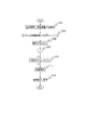
図4は、全体フローチャートである。
まず、測定部600は、露光時間t、測定回数Pを設定する。なお、露光時間t及び測定回数Pは、表示部700より適宜入力してもよいし、予めメモリ800に記憶しておき必要なときに読み出してもよい(ステップS101)。次に、測定部600は、第1受光部(CCD2)21−1及び第2受光部(CCD3)21−2を待機状態にする(ステップS103)。例えば、測定部600は、Grab可能信号をF2=1、F3=1にセットし、制御部610により第1受光部(CCD2)21−1、第2受光部(CCD3)21−2を待機状態にする。
2.2 Flowchart FIG. 4 is an overall flowchart.
First, the
次に、測定部600は、第3受光部(CCD1)41上で得られた前眼部像等により眼のアライメントを行う(ステップS105)。次に、測定部600は、測定済み回数を初期値(例えば、i=1)に設定する(ステップS107)。つぎに、測定部600は、第1受光部21−1が露光している間に第2受光部21−2からデータを読み出し、一方、第2受光部21−2が露光している間に第1受光部21−1からデータを読み出すことにより、ふたつのCCDを用いて被測定眼100の波面測定を実行する(<測定サブルーチン1>)(ステップS111)。測定サブルーチン1についての詳細は後述する。設定した測定回数終了後、測定部600は、測定データをメモリ800から読み出し、それを基に収差解析を行う(ステップS113)。測定部600は、求めた波面収差の解析結果をメモリ(記憶部)800から読み出し、その解析結果に基づいて、例えば、眼の収差データ・マップ、角膜収差データ・マップ、俯瞰図、数値データ、ゼルニケ係数・多項式等を適宜表示するための処理を実行し、その結果を表示部700に表示し、メモリ800に保存する(ステップS115)。
Next, the
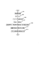
図5は、測定サブルーチン1のフローチャートである。
測定部600は、第1受光部(CCD2)21−1の露光を開始する(ステップS200)。そのために、測定部600は、例えば、Grab可能信号をF2=0にセットし、制御部610により第1受光部(CCD2)21−1の露光を開始する。測定部600は、第1受光部(CCD2)21−1の露光終了を待つ(ステップS201)。
FIG. 5 is a flowchart of the
The
ステップS201で露光が終了すると、測定部600は、第1受光部(CCD2)21−1のデータを読み出してメモリ800に測定回数iに対応したデータIMiとして保存する(ステップS203)。なお、このときCCD2の識別情報をデータIMiに対応して記憶してもよい。次に、測定部600は、P回以上測定したか否かの判断をする(ステップS205)。測定部600は、測定が終了していない場合iの値を加算(i=i+1)し(ステップS207)、制御部610により第1受光部(CCD2)21−1を待機状態(F2=1)にする(ステップS209)。また、ステップS201で露光が終了すると、第1受光部(CCD2)21−1のデータ読み出し処理中(ステップS201〜S209)に、さらに一方で、測定部600は、第2受光部(CCD3)21−2の状態が待機状態(F3=1)か否かの判断をし(ステップS211)、待機状態でなければ待機状態になるまで判断を繰り返す。
When the exposure ends in step S201, the
測定部600は、第2受光部(CCD3)21−2が待機状態であれば第2受光部(CCD3)21−2が露光を開始する(ステップS213)。そのために、測定部600は、例えば、Grab可能信号をF3=0にセットし、制御部610により第2受光部(CCD3)21−2の露光を開始する。測定部600は、第2受光部(CCD3)21−2の露光終了を待つ(ステップS215)。ステップS215で露光が終了すると、測定部600は、第2受光部(CCD3)21−2のデータを読み出してメモリ800に測定回数iに対応したデータIMiとして保存する(ステップS217)。なお、このときCCD3の識別情報をデータIMiに対応して記憶してもよい。次に、測定部600は、P回以上測定したか否かの判断をする(ステップS219)。測定部600は、測定が終了していない場合iの値を加算(i=i+1)し(ステップS221)、制御部610により第2受光部(CCD3)21−2を待機状態に(F3=1)する(ステップS223)。
In the
また、測定部600は、ステップS215で露光が終了すると、第2受光部(CCD3)21−2の処理(ステップS217〜S223)と平行して、第1受光部(CCD2)21−1の状態が待機状態(F2=1)か否かの判断をし(ステップS225)、待機状態でなければ待機状態になるまで判断を繰り返す。
When the exposure is completed in step S215, the measuring
測定部600は、第1受光部(CCD2)21−1が待機状態であれば第1受光部(CCD2)21−1の露光を開始する(ステップS227)。そのために、測定部600は、例えば、Grab可能信号をF2=0にセットし、制御部610より第2受光部(CCD2)21−1の露光を開始する。
以上のように、測定部600は、測定回数P回データ取得の処理を繰り返し行い、ステップS205又はS209で所定の測定回数Pの測定を終了すると測定サブルーチン1の処理を終了する(C2)。
If the first light receiving unit (CCD2) 21-1 is in a standby state, the
As described above, the
2.3 波面収差の解析(ゼルニケ解析とRMS)
以下に、シャックハルトマン波面センサーで波面収差を求める手法の詳細を説明する。
図8は、波面を求めるためのフローチャートである。
測定部600は、ハルトマンイメージから点像の位置を得る(ステップS91)。測定部600は、それぞれの点像(位置)をメモリ800から読み出し、参照位置の対応を得る(ステップS93)。つぎに、測定部600は、点像位置と参照位置の対応より点像位置のずれΔx、Δyを得る(ステップS95)。つぎに、測定部600は、参照点の位置(X、Y)とずれΔx、Δyから、次に説明するように波面W(X、Y)を求めることで、波面収差を解析する(ステップS97)。
2.3 Wavefront aberration analysis (Zernike analysis and RMS)
The details of the method for obtaining the wavefront aberration with the Shack-Hartmann wavefront sensor will be described below.
FIG. 8 is a flowchart for obtaining the wavefront.
The measuring
つぎに、波面収差の解析について説明する。そこで、一般に知られているゼルニケ多項式からゼルニケ係数ci 2j−iを算出する方法について説明する。ゼルニケ係数ci 2j−iは、例えば、各受光部(ハルトマンセンサー)により、ハルトマン板を介してCCDで得られた光束の傾き角に基づいて被測定眼100の光学特性を把握するための重要なパラメータである。
Next, wavefront aberration analysis will be described. Therefore, a method for calculating the Zernike coefficient c i 2j-i from a generally known Zernike polynomial will be described. The Zernike coefficient c i 2j-i is important for grasping the optical characteristics of the
被測定眼100の波面収差W(X,Y)は、ゼルニケ係数ci 2j−i、ゼルニケ多項式Zi 2j−iを用いて次式で表される。

また、波面収差W(X,Y)は、CCDの縦横の座標を(x、y)、ハルトマン板とCCDの距離(ハルトマン板のマイクロレンズの焦点距離)をf、CCDで受光される点像の移動距離を(Δx、Δy)とすると、次式の関係が成り立つ。
ここで、ゼルニケ多項式Zi 2j−iは、次式で表される。
具体的には、図9に、(r,t)座標のゼルニケ多項式の図、及び、図10に、(x,y)座標のゼルニケ多項式の図をそれぞれ示す。
Specifically, FIG. 9 shows a Zernike polynomial with (r, t) coordinates, and FIG. 10 shows a Zernike polynomial with (x, y) coordinates.
なお、ゼルニケ係数ci 2j−iは、次式で表される自乗誤差を最小にすることにより具体的な値を得ることができる。
演算部600は、ゼルニケ係数ci 2j−iを算出し、これを用いて球面収差、コマ収差、非点収差等の眼光学特性を求める。また、演算部600は、ゼルニケ係数ci 2j−iを用いて次式により収差量RMSi 2j−iを算出する。
3.変形例
3.1 半画素分ずらす構成
図6は、複数の受光部(CCD)を半画素分ずらす構成を示す説明図である。この図の例では、第1受光部(CCD2)21−1と第2受光部(CCD3)21−2の配置を示す。
3. Modified Example 3.1 Configuration for Shifting by Half Pixel FIG. 6 is an explanatory diagram showing a configuration for shifting a plurality of light receiving units (CCD) by half pixel. In the example of this figure, the arrangement of the first light receiving part (CCD2) 21-1 and the second light receiving part (CCD3) 21-2 is shown.
CCDの1画素の形状には、例えば、正方形と長方形がある。長方形の場合、長辺側の単位長さあたりの情報量は、短辺側のそれと比べて少なくなる。そこで、本変形例では、2台のCCDを、長辺側に半画素分ずれるようにして配置する。なお、短辺側に半画素分ずらしてもよい。これにより長辺側の情報量を増やすことができ、高精度な測定が可能となる。例えば、1台目の第1受光部(CCD2)21−1は、中心にある画素の中心と光軸が一致するように配置すると、2台目の第2受光部(CCD3)21−2は、中心にある画素とその隣の画素の境目に光軸が一致するように配置する。または、この逆に配置してもよい。 Examples of the shape of one pixel of the CCD include a square and a rectangle. In the case of a rectangle, the amount of information per unit length on the long side is smaller than that on the short side. Therefore, in this modification, the two CCDs are arranged so as to be shifted by half a pixel on the long side. In addition, you may shift by a half pixel to the short side. As a result, the amount of information on the long side can be increased, and highly accurate measurement is possible. For example, when the first first light receiving unit (CCD2) 21-1 is arranged so that the optical axis coincides with the center of the pixel at the center, the second second light receiving unit (CCD3) 21-2 is The optical axis is arranged at the boundary between the pixel in the center and the adjacent pixel. Or you may arrange | position reversely.
このように、第1受光部21−1及び第2受光部21−2は、互いに半画素分ずれて配置されており、測定部600は、第1受光部21−1及び第2受光部21−2からの出力に基づき、一つの受光部からの出力に基づくよりも高精度に収差測定を行うように構成することができる。
Thus, the 1st light-receiving part 21-1 and the 2nd light-receiving part 21-2 are mutually arrange | positioned by a half pixel shift, and the
3.2 装置の収差解析
測定部600は、被測定眼100の測定に先立ち、模型眼などの移動しない対象物を測定対象物として、その際の第1受光部21−1及び第2受光部21−2の出力から、アフィン変換などの変換処理を利用して、互いの位置関係を求める校正モードを実行するようにしてもよい。
3.2 Aberration Analysis of Device Prior to measurement of the
以下に、装置の収差を解析する手法を説明する。
まず、被測定眼100の位置に、収差が分かっている模型眼を配置する。この模型眼を測定すると、既知の収差の他に装置の光学系の収差が加算されている。観察される点像から、収差は式(前に使った式を流用)で算出される。そこから、模型眼の収差を差し引いた量が、装置の収差となる。この収差を点像のずれに直して、そのずれた点像を新たに、本当の参照点とし、測定の際に用いる。
A method for analyzing the aberration of the apparatus will be described below.
First, a model eye whose aberration is known is arranged at the position of the
図7は、装置の収差を求めるフローチャートである。
被検眼100の位置に、収差が予め分かっている模型眼を配置する(ステップS301)。測定部600は、第3受光部(CCD1)41上に形成される前眼部像等により眼のアライメントを行う(ステップS303)。測定部600は、上述の「2.2 フローチャート」で説明したように、又は、第1駆動部620を制御して通常のハルトマン板を利用した波面測定により、制御部610により第1受光部(CCD2)21−1及び第2受光部(CCD3)21−2により点像を取得する(ステップS305)。測定部600は、第1受光部(CCD2)21−1及び第2受光部(CCD3)21−2から読み出した点像から収差解析を行う(ステップS307)。測定部600は、ステップS307により得た解析結果から、模型眼の収差を差し引くことにより、CCD2及び3毎に装置の収差を得る(ステップS309)。測定部600は、ステップS309で求めた装置の収差を点像のずれに変換し(ステップS311)、CCD2及び3にそれぞれ対応してずれた点像を真の参照点とし、メモリ800に記憶する(ステップS313)。測定部600は、各CCD2及び3毎に参照点を基準として測定値Δx、Δyを求め、それに基づき、上述の「2.2 フローチャート」で説明したように波面収差を測定する。
FIG. 7 is a flowchart for determining the aberration of the apparatus.
A model eye whose aberration is known in advance is placed at the position of the
3.3 アフィン変換によるCCDの配置誤差の校正
図11に、各シャックハルトマン波面センサーのCCDの配置誤差の校正についての説明図を示す。
図11(a)に、CCDでの無収差の模型眼を測定したときに得られた点像、図11(b)に、第1受光部21−1又は第2受光部21−2のCCDで得られる点像をそれぞれ示す。図11(b)は、各CCDでアフィン変換のパラメータをもとめる必要がある。さきに計測的に得た、参照点の絶対位置から、決まる点像位置を示す。図示のように整然とならんでいるとは限らないが、ここでは図化が簡単のためにこのように示した。
3.3 Calibration of CCD placement error by affine transformation FIG. 11 is an explanatory diagram for calibration of CCD placement error of each Shack-Hartmann wavefront sensor.
FIG. 11 (a) shows a point image obtained when measuring a non-aberration model eye with a CCD, and FIG. 11 (b) shows the CCD of the first light receiving unit 21-1 or the second light receiving unit 21-2. The point images obtained in are shown respectively. In FIG. 11B, it is necessary to obtain affine transformation parameters for each CCD. The point image position determined from the absolute position of the reference point obtained previously is shown. Although it is not always in order as shown in the figure, it is shown in this way for simplicity of illustration.
一般にCCDは光学器械として、良い精度で組み立てられる。しかし、わずかながら光軸を軸に回転したり、いわゆるあおりがあったり、光軸と垂直の面内で位置ずれしていたりする場合がある。これは、わずかな量であるが、図示のように(図は誇張してある)、無収差模型眼を測定したときの、それぞれのCCDで観察できる点像は、移動したりゆがんだりしている場合がある。例えば、図11(a)は、レンズレットアレイに起因するゆがみや位置移動のみ、図11(b)のCCD上ではCCD起因のゆがみや位置ずれが加わる。 In general, a CCD is assembled with good accuracy as an optical instrument. However, there are cases where the optical axis is slightly rotated, so-called tilting occurs, or the position is displaced in a plane perpendicular to the optical axis. This is a small amount, but as shown in the figure (the figure is exaggerated), the point images that can be observed with each CCD when the non-aberration model eye is measured are moved or distorted. There may be. For example, in FIG. 11A, only distortion and position movement caused by the lenslet array are added, and distortion and position deviation caused by CCD are added on the CCD of FIG. 11B.
図11(a)に示すCCD上での点像と、図11(b)に示す、先立った計測によって得られたCCDの位置、回転誤差がないときの点像の配置(参照点)との間には1対1対応がある。測定部600は、この対応をつけ、2つの点像のアレイ間での関係を、次式に示すアフィン変換によって近似する。
x’=AC1x+BC1y+DC1
y’=AC2x+BC2y+DC2
次に示す各CCDに対する校正パラメータは、メモリ(記憶装置)800に記憶される。
AC1、BC1、DC1
AC2、BC2、DC2
The point image on the CCD shown in FIG. 11A and the CCD image position obtained by the previous measurement shown in FIG. 11B and the arrangement of the point image when there is no rotation error (reference point). There is a one-to-one correspondence between them. The
x '= A C1 x + B C1 y + D C1
y ′ = A C2 x + B C2 y + D C2
The following calibration parameters for each CCD are stored in a memory (storage device) 800.
A C1 , B C1 , D C1
A C2 , B C2 , D C2
3.4 バリエーション
対物レンズの前にλ/4板を挿入して、第1光源部11から第1偏光光学部材(偏光子1)12を通って来た直線偏光を一度円偏光にし、網膜の一部で反射して、位相が反転した円偏光を、このλ/4板で、先ほどと90度偏波面の回転した偏光光にして、第2偏光光学部材(偏光子2)23を透過して、波面測定部分に光が導かれる方法も考えられる。この場合も、第1偏光光学部材(偏光子1)12及び第2偏光光学部材(偏光子2)23の回転により、2つのCCDを使った、高速な波面測定が可能になる。
3.4 Variation A λ / 4 plate is inserted in front of the objective lens, and the linearly polarized light that has passed through the first polarizing optical member (polarizer 1) 12 from the first light source unit 11 is converted into circularly polarized light once. Circularly polarized light that has been partially reflected and inverted in phase is converted to polarized light having a 90-degree polarization plane rotated by this λ / 4 plate and transmitted through the second polarizing optical member (polarizer 2) 23. Thus, a method in which light is guided to the wavefront measurement part can also be considered. Also in this case, the rotation of the first polarizing optical member (polarizer 1) 12 and the second polarizing optical member (polarizer 2) 23 enables high-speed wavefront measurement using two CCDs.
3.5 照明光学系と受光光学系との変形例
上述の説明において、照明光学系と受光光学系において、偏光を利用して光束切り替えを行う例を説明した。しかし、これに限定されるものでなく他の方法も採用可能である。他の例としては、第1照明光学系10において、第1偏光光学部材12また、第1受光光学系20に第1偏光光学部材23を設けず、第1受光光学系20の偏光ビームスプリッタ24を、通常の反射ミラーに交換し、光路から挿脱自在に構成する。反射ミラーは、制御部610からの信号によって、第1受光部と第2受光部との露光タイミングに応じて光路から挿脱自在に制御される。その結果、その反射ミラーが光路から離脱した際には、眼底からの反射光が第1受光部21−1に導かれ、光路に挿入された際には、第2変換部材22−2に導かれるようになる。
3.5 Modified Examples of Illumination Optical System and Light-Receiving Optical System In the above description, an example in which light beams are switched using polarized light in the illumination optical system and the light-receiving optical system has been described. However, the present invention is not limited to this, and other methods can be adopted. As another example, in the first illumination
この発明は、眼科用の測定装置や手術装置等に、幅広く適用することができる。 The present invention can be widely applied to ophthalmic measuring devices, surgical devices, and the like.
10 第1照明光学系11 第1光源部
12 第1偏光光学部材
13 プリズム
14 ビームスプリッタ
20 第1受光光学系
21−1 第1受光部
21−2 第2受光部
22−1 第1変換部材
22−2 第2変換部材
23 第2偏光光学部材
24 偏光ビームスプリッタ
25−1 シャックハルトマン波面センサー1
25−2 シャックハルトマン波面センサー2
40 前眼部観察部
41 第3受光部
50 第1調整光学部
60 前眼部照明部
600 演算部
610 制御部
620 第1駆動部
700 表示部
800 メモリ
DESCRIPTION OF
25-2 Shack-
40 anterior ocular segment observation unit 41 third
Claims (9)
上記光源部からの光束を被測定眼の眼底に照明する照明光学系と、
照明された被測定眼の眼底からの反射光束を選択的に、少なくとも17本の光束に分割する第1及び第2変換部材を介してそれぞれ交互に第1及び第2の受光部に導く受光光学系と、
上記第1及び第2の受光部からの出力に基づき、被測定眼の波面収差を短い間隔で測定する測定部とを有する眼科測定装置。 A light source unit that emits a high-luminance luminous flux at a predetermined timing;
An illumination optical system that illuminates the fundus of the eye to be measured with the light beam from the light source unit;
Light receiving optics for selectively guiding the reflected light beam from the fundus of the illuminated eye to be measured to the first and second light receiving portions alternately via the first and second conversion members that divide the light beam into at least 17 light beams. The system,
An ophthalmologic measurement apparatus comprising: a measurement unit that measures the wavefront aberration of the eye to be measured at short intervals based on outputs from the first and second light receiving units.
上記受光光学系は、上記第1偏光光学部材の偏光条件に応じて照明された被測定眼からの反射光の各偏光成分を選択する第2偏光光学部材と、選択された各偏光成分の反射光をそれぞれ交互に少なくとも17本の光束に分割する光学素子を介して受光する第1及び第2の受光部とを含むように構成されていることを特徴とする眼科測定装置。 The illumination optical system includes a first polarization optical member that alternately changes a polarization condition between the first polarization and the second polarization, and measures a light flux from the light source unit via the first polarization optical member. Illuminate the fundus of the eye,
The light receiving optical system includes a second polarization optical member that selects each polarization component of reflected light from the eye to be measured illuminated according to the polarization condition of the first polarization optical member, and reflection of each selected polarization component. An ophthalmologic measurement apparatus configured to include first and second light receiving units that receive light through optical elements that alternately divide light into at least 17 light beams.
上記測定部は、上記第1及び第2の受光部からの出力に基づき、一つの受光部からの出力に基づくよりも高精度に波面収差測定を行うように構成されていることを特徴とする請求項1記載の眼科測定装置。 The first and second light receiving portions are arranged so as to be shifted from each other by half a pixel,
The measuring unit is configured to perform wavefront aberration measurement with higher accuracy based on outputs from the first and second light receiving units than based on output from one light receiving unit. The ophthalmologic measurement apparatus according to claim 1.
2. The ophthalmologic measurement apparatus according to claim 1, wherein the first and second polarized lights are respectively P-polarized light and S-polarized light or vice versa.
Priority Applications (2)
| Application Number | Priority Date | Filing Date | Title |
|---|---|---|---|
| JP2006076712A JP2007252402A (en) | 2006-03-20 | 2006-03-20 | Ophthalmic apparatus |
| US11/681,420 US7635186B2 (en) | 2006-03-20 | 2007-03-02 | Ophthalmologic measuring apparatus |
Applications Claiming Priority (1)
| Application Number | Priority Date | Filing Date | Title |
|---|---|---|---|
| JP2006076712A JP2007252402A (en) | 2006-03-20 | 2006-03-20 | Ophthalmic apparatus |
Publications (1)
| Publication Number | Publication Date |
|---|---|
| JP2007252402A true JP2007252402A (en) | 2007-10-04 |
Family
ID=38517411
Family Applications (1)
| Application Number | Title | Priority Date | Filing Date |
|---|---|---|---|
| JP2006076712A Pending JP2007252402A (en) | 2006-03-20 | 2006-03-20 | Ophthalmic apparatus |
Country Status (2)
| Country | Link |
|---|---|
| US (1) | US7635186B2 (en) |
| JP (1) | JP2007252402A (en) |
Cited By (4)
| Publication number | Priority date | Publication date | Assignee | Title |
|---|---|---|---|---|
| JP2007275323A (en) * | 2006-04-07 | 2007-10-25 | Topcon Corp | Ophthalmic imaging equipment |
| JP2012034724A (en) * | 2010-08-03 | 2012-02-23 | Topcon Corp | Fundus photographing apparatus |
| JP2020049154A (en) * | 2018-09-28 | 2020-04-02 | スカラ株式会社 | Eyeball imaging apparatus |
| WO2023189793A1 (en) * | 2022-03-29 | 2023-10-05 | ソニーグループ株式会社 | Medical observation device and information processing device |
Families Citing this family (17)
| Publication number | Priority date | Publication date | Assignee | Title |
|---|---|---|---|---|
| US7832864B2 (en) * | 2007-06-15 | 2010-11-16 | The Arizona Board Of Regents On Behalf Of The University Of Arizona | Inverse optical design |
| US7976163B2 (en) * | 2007-06-27 | 2011-07-12 | Amo Wavefront Sciences Llc | System and method for measuring corneal topography |
| US7988290B2 (en) | 2007-06-27 | 2011-08-02 | AMO Wavefront Sciences LLC. | Systems and methods for measuring the shape and location of an object |
| US10398599B2 (en) * | 2007-10-05 | 2019-09-03 | Topcon Medical Laser Systems Inc. | Semi-automated ophthalmic photocoagulation method and apparatus |
| US20100324542A1 (en) * | 2007-11-02 | 2010-12-23 | Kurtz Ronald M | Method to Guide a Cataract Procedure by Corneal Imaging |
| JP4906708B2 (en) * | 2007-12-26 | 2012-03-28 | Hoya株式会社 | Lens imaging device |
| DE102010024606B4 (en) * | 2010-06-22 | 2019-11-14 | Carl Zeiss Meditec Ag | Aberrometric measuring system |
| US8960909B2 (en) * | 2012-01-20 | 2015-02-24 | Canon Kabushiki Kaisha | Control apparatus and control method |
| JP6049310B2 (en) | 2012-06-01 | 2016-12-21 | キヤノン株式会社 | Imaging apparatus, control method, and program |
| JP6049309B2 (en) | 2012-06-01 | 2016-12-21 | キヤノン株式会社 | Measuring device, ophthalmic imaging device, control method, and program |
| JP2013248254A (en) | 2012-06-01 | 2013-12-12 | Canon Inc | Ophthalmic device |
| JP6041539B2 (en) * | 2012-06-01 | 2016-12-07 | キヤノン株式会社 | Ophthalmic equipment |
| JP6041538B2 (en) | 2012-06-01 | 2016-12-07 | キヤノン株式会社 | Ophthalmic equipment |
| JP6041540B2 (en) | 2012-06-01 | 2016-12-07 | キヤノン株式会社 | Ophthalmic equipment |
| US9122926B2 (en) | 2012-07-19 | 2015-09-01 | Honeywell International Inc. | Iris recognition using localized Zernike moments |
| CN104783755A (en) | 2015-04-29 | 2015-07-22 | 中国科学院光电技术研究所 | Adaptive optical retinal imaging apparatus and method |
| CN114777933B (en) * | 2022-06-20 | 2022-09-20 | 中国工程物理研究院应用电子学研究所 | Mesh-free large dynamic range Hartmann wavefront measuring device and measuring method |
Citations (7)
| Publication number | Priority date | Publication date | Assignee | Title |
|---|---|---|---|---|
| JPH05137696A (en) * | 1991-11-19 | 1993-06-01 | Canon Inc | Eyeground image processing method |
| JPH06292653A (en) * | 1993-04-08 | 1994-10-21 | Canon Inc | Optometry device |
| JP2001321340A (en) * | 2000-05-12 | 2001-11-20 | Topcon Corp | Eye characteristics measurement device |
| JP2004081725A (en) * | 2002-08-29 | 2004-03-18 | Topcon Corp | Eye characteristics measurement device |
| JP2004508869A (en) * | 2000-09-21 | 2004-03-25 | カール・ツアイス・スティフツング・トレーディング・アズ・カール・ツアイス | Wavefront reflector for recording two Hartmann-Shack images simultaneously |
| JP2005275305A (en) * | 2004-03-26 | 2005-10-06 | Tokyo Electric Power Co Inc:The | High-speed continuous photographing system, high-speed continuous photographing method, photographed image deviation calibration system, photographed image deviation calibration method, computer program, movement vector calculation system, and movement vector calculation method |
| JP2005333336A (en) * | 2004-05-19 | 2005-12-02 | Olympus Corp | Imaging device |
Family Cites Families (8)
| Publication number | Priority date | Publication date | Assignee | Title |
|---|---|---|---|---|
| US5777719A (en) * | 1996-12-23 | 1998-07-07 | University Of Rochester | Method and apparatus for improving vision and the resolution of retinal images |
| US6027216A (en) * | 1997-10-21 | 2000-02-22 | The Johns University School Of Medicine | Eye fixation monitor and tracker |
| JP3740546B2 (en) | 1997-11-11 | 2006-02-01 | 株式会社トプコン | Ophthalmic measuring device |
| US6050687A (en) * | 1999-06-11 | 2000-04-18 | 20/10 Perfect Vision Optische Geraete Gmbh | Method and apparatus for measurement of the refractive properties of the human eye |
| US6550917B1 (en) | 2000-02-11 | 2003-04-22 | Wavefront Sciences, Inc. | Dynamic range extension techniques for a wavefront sensor including use in ophthalmic measurement |
| DE60228940D1 (en) | 2001-03-15 | 2008-10-30 | Amo Wavefront Sciences Llc | FIGURES FOR ILLUSTRATING AN OPTICAL SYSTEM |
| US6827442B2 (en) * | 2001-09-12 | 2004-12-07 | Denwood F. Ross | Ophthalmic wavefront measuring devices |
| AU2003245458A1 (en) * | 2002-06-12 | 2003-12-31 | Advanced Research And Technology Institute, Inc. | Method and apparatus for improving both lateral and axial resolution in ophthalmoscopy |
-
2006
- 2006-03-20 JP JP2006076712A patent/JP2007252402A/en active Pending
-
2007
- 2007-03-02 US US11/681,420 patent/US7635186B2/en not_active Expired - Fee Related
Patent Citations (7)
| Publication number | Priority date | Publication date | Assignee | Title |
|---|---|---|---|---|
| JPH05137696A (en) * | 1991-11-19 | 1993-06-01 | Canon Inc | Eyeground image processing method |
| JPH06292653A (en) * | 1993-04-08 | 1994-10-21 | Canon Inc | Optometry device |
| JP2001321340A (en) * | 2000-05-12 | 2001-11-20 | Topcon Corp | Eye characteristics measurement device |
| JP2004508869A (en) * | 2000-09-21 | 2004-03-25 | カール・ツアイス・スティフツング・トレーディング・アズ・カール・ツアイス | Wavefront reflector for recording two Hartmann-Shack images simultaneously |
| JP2004081725A (en) * | 2002-08-29 | 2004-03-18 | Topcon Corp | Eye characteristics measurement device |
| JP2005275305A (en) * | 2004-03-26 | 2005-10-06 | Tokyo Electric Power Co Inc:The | High-speed continuous photographing system, high-speed continuous photographing method, photographed image deviation calibration system, photographed image deviation calibration method, computer program, movement vector calculation system, and movement vector calculation method |
| JP2005333336A (en) * | 2004-05-19 | 2005-12-02 | Olympus Corp | Imaging device |
Cited By (4)
| Publication number | Priority date | Publication date | Assignee | Title |
|---|---|---|---|---|
| JP2007275323A (en) * | 2006-04-07 | 2007-10-25 | Topcon Corp | Ophthalmic imaging equipment |
| JP2012034724A (en) * | 2010-08-03 | 2012-02-23 | Topcon Corp | Fundus photographing apparatus |
| JP2020049154A (en) * | 2018-09-28 | 2020-04-02 | スカラ株式会社 | Eyeball imaging apparatus |
| WO2023189793A1 (en) * | 2022-03-29 | 2023-10-05 | ソニーグループ株式会社 | Medical observation device and information processing device |
Also Published As
| Publication number | Publication date |
|---|---|
| US7635186B2 (en) | 2009-12-22 |
| US20070216866A1 (en) | 2007-09-20 |
Similar Documents
| Publication | Publication Date | Title |
|---|---|---|
| US7635186B2 (en) | Ophthalmologic measuring apparatus | |
| KR100888867B1 (en) | Synchronous mapping method and apparatus | |
| JP4776450B2 (en) | Ophthalmic imaging equipment | |
| US7500754B2 (en) | Ophthalmologic imaging apparatus | |
| JP2007518505A (en) | Tomography eye inspection device with aiming device | |
| JP5654271B2 (en) | Ophthalmic equipment | |
| US7490939B2 (en) | Eye characteristics measuring system | |
| JP4684700B2 (en) | Ophthalmic optical characteristic measuring device | |
| JP4252288B2 (en) | Eye characteristic measuring device | |
| EP0663179A1 (en) | Spatial refractometer | |
| JP4231273B2 (en) | Eye characteristics measuring device | |
| JP4630126B2 (en) | Ophthalmic optical characteristic measuring device | |
| JP3898108B2 (en) | Eye characteristics measuring device | |
| US11246484B2 (en) | Methods and systems for eye measurement with in-focus iris and scleral imaging | |
| JP4606560B2 (en) | Ophthalmic optical characteristic measuring device | |
| JP6430770B2 (en) | Ophthalmic equipment | |
| JP4630107B2 (en) | Ophthalmic optical characteristic measuring device | |
| JPH05317255A (en) | Measuring instrument for eye to be examined | |
| JP2007252413A (en) | Ophthalmic measuring device | |
| JP5562621B2 (en) | Ophthalmic equipment | |
| JP5915034B2 (en) | Fundus imaging device with wavefront compensation | |
| JP6567750B2 (en) | Ophthalmic equipment | |
| WO2023145638A1 (en) | Ophthalmic device and ophthalmic program | |
| JP6600198B2 (en) | Optical interference measurement device | |
| WO2025028223A1 (en) | Ophthalmologic measurement apparatus |
Legal Events
| Date | Code | Title | Description |
|---|---|---|---|
| A621 | Written request for application examination |
Free format text: JAPANESE INTERMEDIATE CODE: A621 Effective date: 20081027 |
|
| A977 | Report on retrieval |
Free format text: JAPANESE INTERMEDIATE CODE: A971007 Effective date: 20110415 |
|
| A131 | Notification of reasons for refusal |
Free format text: JAPANESE INTERMEDIATE CODE: A131 Effective date: 20110426 |
|
| A02 | Decision of refusal |
Free format text: JAPANESE INTERMEDIATE CODE: A02 Effective date: 20110830 |