JP2007261202A - Manufacturing method and apparatus for resin sheet - Google Patents
Manufacturing method and apparatus for resin sheet Download PDFInfo
- Publication number
- JP2007261202A JP2007261202A JP2006092301A JP2006092301A JP2007261202A JP 2007261202 A JP2007261202 A JP 2007261202A JP 2006092301 A JP2006092301 A JP 2006092301A JP 2006092301 A JP2006092301 A JP 2006092301A JP 2007261202 A JP2007261202 A JP 2007261202A
- Authority
- JP
- Japan
- Prior art keywords
- roller
- sheet
- resin material
- resin
- mold
- Prior art date
- Legal status (The legal status is an assumption and is not a legal conclusion. Google has not performed a legal analysis and makes no representation as to the accuracy of the status listed.)
- Pending
Links
Images


Landscapes
- Shaping Of Tube Ends By Bending Or Straightening (AREA)
Abstract
【課題】成形時の幅方向の厚さ分布が大きい樹脂シートを製造した際に、欠陥なく所望の断面形状を得ることができ、特に、各種表示装置の背面に配される導光板や各種光学素子に使用するのに好適な樹脂シートの製造方法及び装置を提供する。
【解決手段】ダイ12より押し出したシート状の樹脂材料14とこの樹脂材料の片面側に供給されるバックアップシート20とを樹脂材料が型ローラ16側に、バックアップシートがニップローラ18側になるようにして、型ローラと型ローラに対向配置されるニップローラとで挟圧し、 型ローラ表面の凹凸形状を樹脂材料に転写し、転写後の樹脂材料とバックアップシートとの積層体を型ローラに対向配置される剥離ローラ24に巻き掛けることにより型ローラより剥離する樹脂シートの製造方法である。型ローラの温度を剥離ローラの温度よりも高く制御することにより欠陥を低減できる。
【選択図】 図1
When a resin sheet having a large thickness distribution in the width direction at the time of molding is produced, a desired cross-sectional shape can be obtained without defects, and in particular, a light guide plate and various optical elements arranged on the back surface of various display devices A resin sheet manufacturing method and apparatus suitable for use in an element are provided.
A sheet-like resin material 14 extruded from a die 12 and a backup sheet 20 supplied to one side of the resin material are arranged such that the resin material is on the mold roller 16 side and the backup sheet is on the nip roller 18 side. The mold roller and the nip roller disposed opposite to the mold roller are pressed to transfer the uneven shape on the surface of the mold roller to the resin material, and the laminate of the transferred resin material and the backup sheet is disposed opposite to the mold roller. It is a manufacturing method of the resin sheet which peels from the type | mold roller by winding on the peeling roller 24 to be. Defects can be reduced by controlling the temperature of the mold roller higher than the temperature of the peeling roller.
[Selection] Figure 1
Description
本発明は樹脂シートの製造方法及び装置に係り、特に、各種表示装置の背面に配される導光板や各種光学素子に使用するのに好適な樹脂シートの製造方法及び装置に関する。 The present invention relates to a resin sheet manufacturing method and apparatus, and more particularly to a resin sheet manufacturing method and apparatus suitable for use in a light guide plate and various optical elements disposed on the back surface of various display devices.
各種光学素子に使用される樹脂シートとして、フレネルレンズやレンチキュラーレンズ等が様々な分野で使用されている。このような樹脂シートの表面には、規則的な凹凸形状が形成されており、この凹凸形状により、フレネルレンズやレンチキュラーレンズとしての光学的性能を発揮している。 As resin sheets used for various optical elements, Fresnel lenses, lenticular lenses, and the like are used in various fields. A regular uneven shape is formed on the surface of such a resin sheet, and this uneven shape exhibits optical performance as a Fresnel lens or a lenticular lens.
このような樹脂シートを製造する方法として、これまでに各種の提案がなされている(特許文献1〜4参照)。これらの提案においては、いずれも、生産性向上の観点よりローラ成形方式が採用されている。 As a method for producing such a resin sheet, various proposals have been made so far (see Patent Documents 1 to 4). In these proposals, the roller molding method is adopted from the viewpoint of improving productivity.
たとえば、特許文献1は、樹脂シートをローラから剥離するまでの間の冷却手段に工夫を施すことにより、転写性の向上を図っている。特許文献2は、ローラに金型を巻き付けてフレネルレンズを製造する方法を開示している。 For example, Patent Document 1 attempts to improve transferability by devising the cooling means until the resin sheet is peeled from the roller. Patent Document 2 discloses a method of manufacturing a Fresnel lens by winding a die around a roller.
特許文献3は、成形ローラの内部に熱緩衝部材を配して、生産性及び転写性の向上を図っている。特許文献4は、コロナ放電処理を採用することにより、転写性の向上、欠陥の低減を図っている。 In Patent Document 3, a heat buffer member is arranged inside the forming roller to improve productivity and transferability. Patent Document 4 uses a corona discharge treatment to improve transferability and reduce defects.
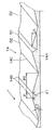
これら従来技術の代表的なローラ成形方式は、図6に示される構成のようになっている。この装置構成は、押出し機(図示略)によって溶融された樹脂材料1をシート状に賦形するためのシート用のダイ2と、表面に凹凸形状が形成されたスタンパーローラ3と、スタンパーローラ3に対向配置される鏡面ローラ4と、スタンパーローラ3に対向するとともに、鏡面ローラ4の反対側に配置される剥離用鏡面ローラ5よりなる。 A typical roller forming method of these prior arts is configured as shown in FIG. This apparatus configuration includes a sheet die 2 for shaping a resin material 1 melted by an extruder (not shown) into a sheet shape, a stamper roller 3 having an uneven surface formed thereon, and a stamper roller 3. And a mirror roller 4 for peeling, which is disposed opposite to the mirror roller 4 while facing the stamper roller 3.
そして、ダイ2より押し出したシート状の樹脂材料1を、スタンパーローラ3と鏡面ローラ4とで挟圧し、スタンパーローラ3表面の凹凸形状を樹脂材料1に転写し、樹脂材料1を剥離用鏡面ローラ5に巻き掛けることによりスタンパーローラ3より剥離する。
しかしながら、上記従来の提案は、いずれも、比較的薄肉の樹脂シートを製造する方法に関するものであり、比較的厚肉の樹脂シートの製造には適していない。特に、成形時の幅方向の厚さ分布が大きい樹脂シートを製造した場合には、所望の断面形状を得るのが非常に困難である。 However, any of the above conventional proposals relates to a method for producing a relatively thin resin sheet, and is not suitable for producing a relatively thick resin sheet. In particular, when a resin sheet having a large thickness distribution in the width direction during molding is produced, it is very difficult to obtain a desired cross-sectional shape.
たとえば、PMMA(ポリメチルメタクリレート樹脂)を押し出し後にローラ成形する際に、幅方向に厚さ分布を付け、最厚肉部と最薄肉部との厚さの差を1mm以上とした場合、表面又は裏面に凹凸(樹脂の硬化時の収縮による引け、弾性回復量分布)を生じたり、全体的に表面形状転写率が低下したり、シャープエッジ形状が転写できなかったり、各種の問題がある。 For example, when PMMA (polymethylmethacrylate resin) is extruded and then subjected to roller molding, when the thickness distribution is given in the width direction and the difference in thickness between the thickest part and the thinnest part is 1 mm or more, the surface or There are various problems such as unevenness on the back surface (shrinkage due to shrinkage when the resin is cured, distribution of elastic recovery amount), overall surface shape transfer rate is reduced, and sharp edge shape cannot be transferred.
また、上記従来の提案では、既述の図6に示される構成において、スタンパーローラ3、鏡面ローラ4、剥離用鏡面ローラ5の順で設定温度が高くなるように温度を制御するのが一般的である。すなわち、下流側のローラ温度を上流側のローラ温度よりも高くして、下流側のローラと樹脂との接着力を高め、これにより、下流側のローラに樹脂が移るようにしている。 In the conventional proposal, in the configuration shown in FIG. 6, the temperature is generally controlled so that the set temperature becomes higher in the order of the stamper roller 3, the mirror roller 4, and the peeling mirror roller 5. It is. In other words, the downstream roller temperature is set higher than the upstream roller temperature to increase the adhesive force between the downstream roller and the resin, so that the resin is transferred to the downstream roller.
ところが、このようなローラ温度の設定を行うと、剥離させる段階で樹脂の温度が高くなり過ぎ、剥離用鏡面ローラ5から樹脂が剥離しにくいという問題がある。そして、これにより成形後の樹脂シートの凹凸形状の欠陥となることが多い。 However, when such a roller temperature is set, the temperature of the resin becomes too high at the stage of peeling, and there is a problem that the resin is difficult to peel from the peeling mirror roller 5. And it becomes a defect of the uneven | corrugated shape of the resin sheet after shaping | molding by this in many cases.
本発明はこのような事情に鑑みてなされたもので、成形時の幅方向の厚さ分布が大きい樹脂シートを製造した際に、欠陥なく所望の断面形状を得ることができ、特に、各種表示装置の背面に配される導光板や各種光学素子に使用するのに好適な樹脂シートの製造方法及び装置を提供することを目的とする。 The present invention has been made in view of such circumstances, and when a resin sheet having a large thickness distribution in the width direction at the time of molding can be produced, a desired cross-sectional shape can be obtained without defects, in particular, various displays. It aims at providing the manufacturing method and apparatus of a resin sheet suitable for using for the light-guide plate and various optical elements which are distribute | arranged to the back surface of an apparatus.
本発明は、前記目的を達成するために、ダイより押し出したシート状の樹脂材料と該樹脂材料の片面側に供給されるバックアップシートとを前記樹脂材料が型ローラ側に、前記バックアップシートがニップローラ側になるようにして、前記型ローラと該型ローラに対向配置される前記ニップローラとで挟圧し、該型ローラ表面の凹凸形状を前記樹脂材料に転写し、転写後の前記樹脂材料と前記バックアップシートとの積層体を該型ローラに対向配置される剥離ローラに巻き掛けることにより該型ローラより剥離する樹脂シートの製造方法であって、前記型ローラの温度を前記剥離ローラの温度よりも高く制御することを特徴とする樹脂シートの製造方法を提供する。 In order to achieve the above object, the present invention provides a sheet-like resin material extruded from a die and a backup sheet supplied to one side of the resin material on the mold roller side, and the backup sheet is a nip roller. The mold roller and the nip roller disposed opposite to the mold roller are pressed so as to transfer the uneven shape on the mold roller surface to the resin material, and the resin material after the transfer and the backup A method of manufacturing a resin sheet that is peeled off from a mold roller by winding a laminate with a sheet on a peeling roller disposed opposite to the mold roller, wherein the temperature of the mold roller is higher than the temperature of the peeling roller Provided is a method for producing a resin sheet characterized by controlling.
また、このために、本発明は、周面に凹凸形状が形成された型ローラと、該型ローラの一方側に対向配置されるニップローラと、該型ローラの他方側に対向配置される剥離ローラとよりなり、前記型ローラ、ニップローラ、剥離ローラの順で設定温度が下がるように温度制御されるローラ列と、シート状の樹脂材料を吐出口より押し出すダイと、帯状可撓性のバックアップシートを供給するバックアップシート供給手段と、を備え、前記ダイより押し出された樹脂材料が型ローラ側に、前記バックアップシートが前記ニップローラ側になるようにして、前記型ローラと前記ニップローラとで挟圧され、該型ローラ表面の凹凸形状が前記樹脂材料に転写され、転写後の前記樹脂材料と前記バックアップシートとの積層体が前記剥離ローラに巻き掛けられて該型ローラより剥離されることを特徴とする樹脂シートの製造装置を提供する。 To this end, the present invention provides a mold roller having a concavo-convex shape formed on the peripheral surface, a nip roller disposed opposite to one side of the mold roller, and a peeling roller disposed opposite to the other side of the mold roller. A roller array whose temperature is controlled so as to lower the set temperature in the order of the mold roller, the nip roller, and the peeling roller, a die for extruding the sheet-like resin material from the discharge port, and a belt-like flexible backup sheet. Backup sheet supply means for supplying, the resin material extruded from the die is sandwiched between the mold roller and the nip roller, with the backup sheet on the nip roller side and the backup sheet on the nip roller side, The uneven shape on the surface of the mold roller is transferred to the resin material, and the laminate of the resin material and the backup sheet after the transfer is wound around the peeling roller. Vignetting to provide an apparatus for manufacturing a resin sheet, characterized in that it is separated from the mold roller.
本発明によれば、ダイより押し出した樹脂材料と、この樹脂材料の片面側に供給されるバックアップシートとを樹脂材料が型ローラ側に、バックアップシートがニップローラ側になるようにして、型ローラとニップローラとで挟圧し、型ローラ表面の凹凸形状を樹脂材料に転写する。すなわち、樹脂材料の裏面はバックアップシートを介して各ローラと接する。したがって、下流側のローラ温度を上流側のローラ温度よりも高くしなくても、下流側のローラに樹脂が容易に移る。したがって、剥離ローラから樹脂が剥離しにくいという問題が解消できる。 According to the present invention, the resin material extruded from the die and the backup sheet supplied to one side of the resin material are placed on the mold roller side so that the resin material is on the mold roller side and the backup sheet is on the nip roller side. Clamping is performed with a nip roller to transfer the uneven shape on the surface of the mold roller to the resin material. That is, the back surface of the resin material is in contact with each roller through the backup sheet. Therefore, the resin easily transfers to the downstream roller without setting the downstream roller temperature higher than the upstream roller temperature. Therefore, the problem that the resin is difficult to peel from the peeling roller can be solved.
また、本発明によれば、型ローラの温度を剥離ローラの温度よりも高く制御するので、言い換えれば、剥離ローラの温度を型ローラの温度よりも低く制御するので、樹脂とバックアップシートとの接触面の冷却が促進され、樹脂とバックアップシートとの剥離性も良好となる。 According to the present invention, the temperature of the mold roller is controlled to be higher than the temperature of the peeling roller. In other words, the temperature of the peeling roller is controlled to be lower than the temperature of the mold roller, so Cooling of the surface is promoted, and the peelability between the resin and the backup sheet is improved.
本発明において、前記ニップローラの温度を前記剥離ローラの温度よりも高く、かつ、前記型ローラの温度を前記ニップローラの温度よりも高く制御することが好ましい。このように、下流側のローラ温度を上流側のローラ温度よりも低く制御するので、各ローラから樹脂が剥離しにくいという問題が一層解消できる。 In the present invention, it is preferable to control the temperature of the nip roller higher than the temperature of the peeling roller and the temperature of the mold roller higher than the temperature of the nip roller. Thus, since the downstream roller temperature is controlled to be lower than the upstream roller temperature, the problem that the resin is difficult to peel off from each roller can be further solved.
また、本発明において、前記樹脂材料に転写される凹凸形状により、該樹脂材料の幅方向における最厚肉部と最薄肉部との厚さの差が1mm以上となることが好ましい。また、本発明において、前記樹脂材料の最薄肉部の厚さが5mm以下であることが好ましい。このように、従来、成形が困難であった、断面形状の樹脂材料の成形において、本発明の効果が発揮できる。 In the present invention, it is preferable that the difference in thickness between the thickest portion and the thinnest portion in the width direction of the resin material is 1 mm or more due to the uneven shape transferred to the resin material. Moreover, in this invention, it is preferable that the thickness of the thinnest part of the said resin material is 5 mm or less. Thus, the effect of the present invention can be exhibited in the molding of a resin material having a cross-sectional shape that has been difficult to mold.
また、本発明において、転写後の前記樹脂材料と前記バックアップシートとの積層体を前記型ローラより剥離した後に又は前記型ローラ上で、該樹脂材料より前記バックアップシートを剥離することが好ましい。このように、転写後に樹脂材料よりバックアップシートを剥離すれば、製品としての樹脂材料の扱いが容易となる。 In the present invention, it is preferable that the backup sheet is peeled off from the resin material after the laminated body of the resin material and the backup sheet after transfer is peeled off from the mold roller or on the mold roller. As described above, if the backup sheet is peeled off from the resin material after the transfer, it becomes easy to handle the resin material as a product.
また、本発明において、前記樹脂材料より剥離後の前記バックアップシートにクリーニングを施すことが好ましい。このように、剥離後のバックアップシートにクリーニングを施せば、バックアップシートを再利用する際に便宜である。 Moreover, in this invention, it is preferable to clean the said backup sheet after peeling from the said resin material. In this way, if the backup sheet after peeling is cleaned, it is convenient when the backup sheet is reused.
また、本発明において、前記バックアップシートを無端環状の帯状体とすることが好ましい。このように、バックアップシートをエンドレスベルト状とすれば、バックアップシートの搬送が容易となり、また、バックアップシートの長さを短縮できる。 In the present invention, it is preferable that the backup sheet is an endless annular band. As described above, when the backup sheet has an endless belt shape, the backup sheet can be easily conveyed and the length of the backup sheet can be shortened.
また、本発明において、前記バックアップシートを連続的に供給するシート繰り出し手段、及び前記バックアップシートを収納するシート巻回手段を設けることが好ましい。このように、シート繰り出し手段とシート巻回手段を設けることにより、バックアップシートの取り扱いが極めて容易になる。 In the present invention, it is preferable to provide sheet feeding means for continuously supplying the backup sheet and sheet winding means for storing the backup sheet. Thus, by providing the sheet feeding means and the sheet winding means, the backup sheet can be handled very easily.
以上説明したように、本発明によれば、成形時の幅方向の厚さ分布が大きい樹脂シートであっても、欠陥なく所望の断面形状を得ることができる。 As described above, according to the present invention, a desired cross-sectional shape can be obtained without defects even in a resin sheet having a large thickness distribution in the width direction during molding.
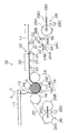
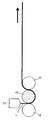
以下、添付図面に従って、本発明に係る樹脂シートの製造方法及び装置の好ましい実施の形態(第1実施形態)について詳説する。図1は、本発明に係る樹脂シートの製造方法が適用される、樹脂シートの製造ラインの例を示す構成図である。 Hereinafter, a preferred embodiment (first embodiment) of a resin sheet manufacturing method and apparatus according to the present invention will be described in detail with reference to the accompanying drawings. FIG. 1 is a configuration diagram showing an example of a resin sheet production line to which a resin sheet production method according to the present invention is applied.
この樹脂シートの製造ライン10は、押出し機11によって溶融された樹脂材料14をシート状に賦形するためのシート用のダイ12と、表面に凹凸形状が形成された型ローラ16と、型ローラ16に対向配置されるニップローラ18と、型ローラ16に対向配置される剥離ローラ24と、バックアップシート20を連続的に供給するシート繰り出し手段26と、バックアップシート20を収納するシート巻回手段28と、樹脂材料14及びバックアップシート20の搬送を支持する複数のガイドローラ22、22…等とより構成されている。
The resin sheet production line 10 includes a
ダイ12のスリットサイズは、成形された溶融樹脂材料14の幅が型ローラ16の型の幅よりも広くなるように形成され、また、このダイ12から押し出される溶融樹脂材料14が型ローラ16とニップローラ18との間に押し出されるように配置されている。特に重要なことは、ダイ12の吐出口(中心線が符号Cで示される)を、型ローラ16とニップローラ18との共通接線Sに対し型ローラ16側に設けることである。このような配置とすることにより、樹脂材料14とバックアップシート20との間に空気を混入することが大幅に低減し、成形後の樹脂シートの裏面欠陥が大幅に低減する。
The slit size of the
型ローラ16の表面には、規則的な凹凸形状が形成されている。この規則的な凹凸形状は、たとえば、図2に示される成形後の樹脂材料14の反転形状とすることができる。この図2は、成形後の樹脂材料14の端面14Aを直線状に切り取った状態の斜視図である。
A regular uneven shape is formed on the surface of the
すなわち、樹脂材料14の裏面は平面であり、樹脂材料14の表面に矢印に平行な直線状の凹凸パターンが形成されている。この矢印は、樹脂材料14の走行方向を示す。したがって、型ローラ16の表面には、端面14Aの反転形状のエンドレス溝を形成すればよい。なお、樹脂材料14表面の凹凸パターン形状の詳細については後述する。
That is, the back surface of the
型ローラ16の材質としては、各種鉄鋼部材、ステンレス鋼、銅、亜鉛、真鍮、これらの金属材料を芯金として、表面にゴムライニングしたもの、これらの金属材料にHCrメッキ、Cuメッキ、Niメッキ等のメッキを施したもの、セラミックス、及び各種の複合材料が採用できる。
The material of the
型ローラ16表面の凹凸パターン形成方法としては、凹凸パターン(ピッチ、深さ、等)や型ローラ16表面の材質にもよるが、一般的にはNC旋盤による切削加工と仕上げバフ加工との組み合わせが好ましく採用できる。また、他の公知の加工方法(研削加工、超音波加工、放電加工、等)も採用できる。
The method for forming the concavo-convex pattern on the surface of the
型ローラ16表面の表面粗さは、Raで0.5μm以下とするのが好ましく、0.2μm以下とするのがより好ましい。
The surface roughness of the surface of the
型ローラ16は、図示しない駆動手段により、所定の周速度で図1の矢印方向に回転駆動されるようになっている。また、型ローラ16には、温度調節手段が施されている。このような温度調節手段が設けられることにより、高温状態の樹脂材料14による型ローラ16の温度上昇や急激な温度低下を抑制すべく制御できる。
The
このような温度調節手段としては、ローラ内部に温度調節したオイルを循環させる構成が好ましく採用できる。このオイルの供給と排出は、ローラの端部にロータリージョイントを設ける構成により実現できる。図1の樹脂シートの製造ライン10においては、この温度調節手段が採用されている。 As such temperature adjusting means, a configuration in which oil whose temperature is adjusted is circulated inside the roller can be preferably employed. This supply and discharge of oil can be realized by a configuration in which a rotary joint is provided at the end of the roller. In the resin sheet production line 10 of FIG. 1, this temperature adjusting means is employed.
ニップローラ18は、型ローラ16に対向配置され、型ローラ16とにより樹脂材料14とこの背面に積層されたバックアップシート20を挟圧するためのローラで、走行方向上流側において型ローラ16と同一高さに配置されている。
The
ニップローラ18の表面は鏡面状に加工されていることが好ましい。このような表面とすることにより、成形後の樹脂材料14の裏面を良好な状態にできる。そして、ニップローラ18表面の表面粗さは、Raで0.5μm以下とするのが好ましく、0.2μm以下とするのがより好ましい。
The surface of the
ニップローラ18の材質としては、各種鉄鋼部材、ステンレス鋼、銅、亜鉛、真鍮、これらの金属材料を芯金として、表面にゴムライニングしたもの、これらの金属材料にHCrメッキ、Cuメッキ、Niメッキ等のメッキを施したもの、セラミックス、及び各種の複合材料が採用できる。
The material of the
ニップローラ18は、図示しない駆動手段により、所定の周速度で図1の矢印方向に回転駆動されるようになっている。なお、ニップローラ18に駆動手段を設けない構成も可能であるが、樹脂材料14の裏面を良好な状態にできる点より、駆動手段を設けることが好ましい。
The
ニップローラ18には、図示しない加圧手段が設けられており、型ローラ16との間の樹脂材料14を所定の圧力で挟圧できるようになっている。この加圧手段は、ニップローラ18と型ローラ16との接触点における法線方向に圧力を印加する構成のもので、モータ駆動手段、エアシリンダ、油圧シリンダ等の公知の各種手段が採用できる。
The
ニップローラ18には、挟圧力の反力による撓みが生じにくくなるような構成を採用することもできる。このような構成としては、ニップローラ18の背面側(型ローラ16の反対側)にバックアップローラを設ける構成、クラウン形状(中高形状とする)を採用する構成、ローラの軸方向中央部の剛性が大きくなるような強度分布を付けたローラの構成、及びこれらを組み合わせた構成等が採用できる。
The
ニップローラ18には、温度調節手段が施されている。ニップローラ18のローラ設定温度は、樹脂材料14の材質、樹脂材料14の溶融時(たとえば、ダイ12のスリット出口)の温度、樹脂材料14の搬送速度、型ローラ16の外径、型ローラ16の凹凸パターン形状等によって最適な値を選択すべきである。
The
ニップローラ18のローラ温度調節手段としては、ローラ内部に温度調節したオイルを循環させる構成が好ましく採用できる。このオイルの供給と排出は、ローラの端部にロータリージョイントを設ける構成により実現できる。図1の樹脂シートの製造ライン10においては、この温度調節手段が採用されている。
As the roller temperature adjusting means of the
他の温度調節手段としては、たとえば、ローラの内部にシースヒータを埋め込む構成、ローラの近傍に誘電加熱手段を配する構成等、公知の各種手段が採用できる。 As other temperature adjusting means, for example, various known means such as a structure in which a sheath heater is embedded in the roller and a structure in which a dielectric heating means is disposed in the vicinity of the roller can be adopted.
バックアップシート20としては、樹脂フィルム、金属箔(アルミニウムウェブ、鉄、ステンレス鋼、銅、真鍮、亜鉛等)等を使用できる。樹脂フィルムの材質としては、ポリエチレン、ポリプロピレン、ポリ塩化ビニル、ポリ塩化ビニリデン、ポリ酢酸ビニル、ポリスチレン、ポリカーボネート、ポリアミド、PET(ポリエチレンテレフタレート)、二軸延伸を行ったポリエチレンテレフタレート、ポリエチレンナフタレート、ポリアミドイミド、ポリイミド、芳香族ポリアミド、セルローストリアセテート、セルロースアセテートプロピオネート、セルロースダイアセテート等の公知のものが使用できる。これらのうち、特にポリエチレンテレフタレート、ポリエチレンナフタレート、ポリアミドが好ましく使用できる。
As the
バックアップシート20のガラス転移温度Tg20は、樹脂材料14のガラス転移温度Tg14より大であることが好ましい。このように、バックアップシート20の熱変形が樹脂材料14より小であれば、バックアップシート20の変形が防止できる。
Glass transition temperature Tg 20 of the
また、バックアップシート20の縦弾性係数が使用環境下で1×10⁹N/mm2以上であることが好ましい。このように、バックアップシート20の縦弾性係数(いわゆるヤング率)が適正範囲にあれば、バックアップシート20の剛性により樹脂材料14の過度の変形が防止できる。
Moreover, it is preferable that the longitudinal elastic modulus of the
また、バックアップシート20の厚さが0. 5〜100μmであることが好ましい。このような厚さのバックアップシート20であれば、適度な可撓性と適度な剛性が得られる。
Moreover, it is preferable that the thickness of the
バックアップシート20の幅としては、樹脂材料14の幅と略同一サイズが好ましく、バックアップシート20の長さとしては、1000〜100000mが一般的に採用される。ただし、これ以外のサイズの適用も妨げられるものではない。
The width of the
これらのバックアップシート20は、あらかじめコロナ放電、プラズマ処理、易接着処理、熱処理、除塵処理などを行っておいてもよい。バックアップシート20の表面粗さRaはカットオフ値0.25mmにおいて3〜10nmが好ましい。
These
なお、バックアップシート20の樹脂材料14と接する面の略全面に凹凸形状、たとえば、エンボス加工形状、ブラッシング形状、ブラスト形状、ピーニング形状、プリズム形状等を施すこともできる。このようにすれば、樹脂材料14の裏面もこの反転形状にできる。
In addition, an uneven shape, for example, an embossed shape, a brushing shape, a blasting shape, a peening shape, a prism shape, or the like, can be applied to substantially the entire surface of the
シート繰り出し手段26は、バックアップシート20を連続的に供給するものであり、支持腕26Dの両端部に、バックアップシート20が巻回され繰り出し中の原反ロール26Aと、新規の(予備の)原反ロール26Bが設けられており、支点26Cを回動中心とした支持腕26Dの回動により、バックアップシート20を連続走行させながら、繰り出し中の原反ロール26Aと、新規の(予備の)原反ロール26Bとを交換できるようになっている。
The sheet feeding means 26 continuously supplies the
シート繰り出し手段26より繰り出されたバックアップシート20は、ガイドローラ22を経て樹脂材料14の背面に供給され、型ローラ16とニップローラ18との間に送り込まれるようになっている。
The
型ローラ16の下側には、ニップローラ18から剥離ローラ24に向って3個の補助ローラ19(上流から順に、第1の補助ローラ19A、第2の補助ローラ19B、第3の補助ローラ19C)が配されている。この補助ローラ19は、ニップローラ18の押圧の補助、及び樹脂材料14の冷却を目的として設けられている。
Below the
したがって、補助ローラ19には、温度調節手段が施されている。補助ローラ19のローラ設定温度は、樹脂材料14の材質、樹脂材料14の溶融時(たとえば、ダイ12のスリット出口)の温度、樹脂材料14の搬送速度、型ローラ16の外径、型ローラ16の凹凸パターン形状等によって最適な値を選択すべきである。
Therefore, the
剥離ローラ24は、型ローラ16に対向配置され、樹脂材料14とバックアップシート20の積層体を巻き掛けることにより樹脂材料14を型ローラ16より剥離するためのローラで、型ローラ16を挟んでニップローラ18の180度下流側に配置されている。なお、剥離ローラ24の配置は、これ以外の態様も可能である。
The peeling
剥離ローラ24の表面は鏡面状に加工されていることが好ましい。このような表面とすることにより、成形後の樹脂材料14の裏面を良好な状態にできる。そして、剥離ローラ24表面の表面粗さは、Raで0.5μm以下とするのが好ましく、0.2μm以下とするのがより好ましい。
The surface of the peeling
剥離ローラ24の材質としては、各種鉄鋼部材、ステンレス鋼、銅、亜鉛、真鍮、これらの金属材料を芯金として、表面にゴムライニングしたもの、これらの金属材料にHCrメッキ、Cuメッキ、Niメッキ等のメッキを施したもの、セラミックス、及び各種の複合材料が採用できる。
As the material of the peeling
剥離ローラ24は、図示しない駆動手段により、所定の周速度で図1の矢印方向に回転駆動されるようになっている。なお、剥離ローラ24に駆動手段を設けない構成も可能であるが、樹脂材料14の裏面を良好な状態にできる点より、駆動手段を設けることが好ましい。
The peeling
剥離ローラ24には、温度調節手段が施されている。そして、適正な設定温度にすることにより、樹脂材料14の表面の凹凸パターン形状を良好にできる。
The peeling
以上に説明した各ローラ、及び、樹脂材料14の各箇所の表面温度がモニターできるように、表面温度測定手段(図示略)を設けることが好ましい。このような表面温度測定手段としては、赤外線温度計、放射式温度計等の公知の各種測定手段が採用できる。
It is preferable to provide surface temperature measuring means (not shown) so that the surface temperatures of the respective rollers and the
このような表面温度測定手段による測定箇所としては、たとえば、ダイ12と型ローラ16との間の樹脂材料14の幅方向の複数点、剥離ローラ24の直後の樹脂材料14の幅方向の複数点、型ローラ16や剥離ローラ24に巻き掛けられている樹脂材料14の幅方向の複数点の表面(ローラの反対面側)、等が考えられる。
Examples of measurement points by such surface temperature measuring means include a plurality of points in the width direction of the
また、このような表面温度測定手段のモニター結果を各ローラの温度調節手段やダイ12等にフィードバックして各ローラ等の温度制御に反映させることもできる。なお、表面温度測定手段を設けずに、フィードフォワード制御により運転することも可能である。
In addition, the monitoring result of the surface temperature measuring means can be fed back to the temperature adjusting means of each roller, the
図1の樹脂シートの製造ライン10又はその下流に、樹脂材料14の張力を検出するテンション検出手段を設けたり、樹脂材料14の板厚を検出する板厚検出手段(厚さセンサ)を設けたりすることも、好ましく採用できる。また、このような検出手段による検出結果を設定値と比較し、後述するドロー制御(第2実施形態)にフィードバックすることもできる。
A tension detecting means for detecting the tension of the
徐冷ゾーン30(又はアニーリングゾーン)は、剥離ローラ24の下流における樹脂材料14の急激な温度変化を防止するために設けられたものである。樹脂材料14に急激な温度変化を生じた場合、たとえば、樹脂材料14の表面近傍が弾性状態になっているのに、樹脂材料14の内部が塑性状態であり、この部分の硬化による収縮で樹脂材料14の表面形状が悪化する。また、樹脂材料14の表裏面に温度差を生じ、樹脂材料14に反りを生じる不具合もある。
The slow cooling zone 30 (or annealing zone) is provided to prevent a rapid temperature change of the
徐冷ゾーン30としては、水平方向のトンネル形状とし、トンネル内部に温度調節手段を設け、樹脂材料14の冷却温度プロファイルを制御できる構成が採用できる。温度調節手段としては、複数のノズルより温度制御されたエア(温風又は冷風)を樹脂材料14に向けて噴出させる構成、加熱手段(ニクロム線ヒータ、赤外線ヒータ、誘電加熱手段等)により、樹脂材料14の表裏面をそれぞれ加熱する構成等、公知の各種手段が採用できる。
As the
徐冷ゾーン30(又はアニーリングゾーン)の下流には、剥離部32が形成されている。この剥離部32において、樹脂材料14はガイドローラ22、22…で支持されて、直線状に右方に搬送され、バックアップシート20はガイドローラ22、22…で支持されて、右下方に搬送される。
A peeling
このように、剥離部32において樹脂材料14よりバックアップシート20を剥離すれば、製品としての樹脂材料14の扱いが容易となる。
Thus, if the
剥離部32の下流には、樹脂材料14に対して、洗浄装置(洗浄ゾーン)、欠陥検査装置(検査ゾーン)、ラミネート装置、サイドカッター、クロスカッター、集積部が順に設けられる(いずれも図示を略す)。
A cleaning device (cleaning zone), a defect inspection device (inspection zone), a laminating device, a side cutter, a cross cutter, and an accumulating portion are sequentially provided downstream of the peeling
このうち、ラミネート装置は、樹脂材料14の表裏面に保護フィルム(ポリエチレン等のフィルム)を貼り付ける装置であり、サイドカッターは、樹脂材料14の幅方向両端部分(捨て部分)を切除する装置であり、クロスカッターは、樹脂材料14を所定長さに切り揃える装置である。
Among these, the laminating apparatus is an apparatus that attaches a protective film (a film such as polyethylene) to the front and back surfaces of the
上記装置のうち、用途に応じて、いくつかを省略することもできる。 Some of the above devices may be omitted depending on the application.
剥離部32の下流には、バックアップシート20に対して、ダンサーローラ34、クリーニング手段(図示略)、駆動ローラ36、シート巻回手段28が順に設けられている。
A
このうち、ダンサーローラ34は、バックアップシート20のテンション(張力)を調整するためのもので、回動支点34Aと、一端が回動支点34Aで支持される回動腕34Bと、回動腕34Bの他端に支持されるローラ34Cとより構成される。そして、回動腕34Bが図の矢印方向に付勢されることにより、バックアップシート20のテンションが調整できるようになっている。
Among them, the
クリーニング手段は、バックアップシート20の表面に付着した塵埃等の汚染(コンタミネーション)を除去するためのもので、クリーニングテープ又はクリーニングローラをバックアップシート20に押し付けるタイプのものや、除電したクリーンエア(窒素ガス等でも可)をバックアップシート20に吹き付けるタイプのもの等、公知の各種手段が採用できる。
The cleaning means is for removing contamination (contamination) such as dust adhering to the surface of the
駆動ローラ36は、ローラ36Aとローラ36Bとでバックアップシート20を挟み(ニップし)バックアップシート20を搬送させるための機構であり、ローラ36Aとローラ36Bの少なくとも1方が回転駆動されるようになっている。
The
シート巻回手段28は、バックアップシート20を収納するものであり、支持腕28Dの両端部に、バックアップシート20が巻回され収納中の巻き芯28Aと、新規の(予備の)巻き芯28Bが設けられており、支点28Cを回動中心とした支持腕28Dの回動により、バックアップシート20を連続走行させながら、収納中の巻き芯28Aと、新規の(予備の)巻き芯28Bとを交換できるようになっている。
The sheet winding means 28 stores the
次に、図1に示される樹脂シートの製造ライン10による樹脂シートの製造方法について説明する。 Next, a method for producing a resin sheet by the resin sheet production line 10 shown in FIG. 1 will be described.
本発明に適用される樹脂材料14としては、熱可塑性樹脂を用いることができ、たとえば、ポリメチルメタクリレート樹脂(PMMA)、ポリカーボネート樹脂、ポリスチレン樹脂、MS樹脂、AS樹脂、ポリプロピレン樹脂、ポリエチレン樹脂、ポリエチレンテレフタレート樹脂、ポリ塩化ビニル樹脂(PVC)、熱可塑性エラストマー、又はこれらの共重合体、シクロオレフィンポリマー等が挙げられる。
As the
ダイ12より押し出したシート状の樹脂材料14と、シート繰り出し手段26より繰り出され、樹脂材料14の裏面に供給されたバックアップシート20との積層体を、型ローラ16と型ローラ16に対向配置されるニップローラ18とで挟圧し、型ローラ16表面の凹凸形状を樹脂材料14に転写し、樹脂材料14とバックアップシート20との積層体を型ローラ16に対向配置される剥離ローラ24に巻き掛けることにより型ローラ16より剥離する。
A laminated body of the sheet-
この際、型ローラ16とニップローラ18と剥離ローラ24の表面温度を、型ローラ16、ニップローラ18、剥離ローラ24の順で低くなるように制御する。これにより、バックアップシート20の使用による効果と相俟って、各ローラからの樹脂材料14の剥離性が向上する。
At this time, the surface temperatures of the
また、ダイ12の吐出口(中心線が符号Cで示される)が、型ローラ16とニップローラ18との共通接線Sに対し型ローラ16側に設けられているので、樹脂材料14とバックアップシート20との間に空気を混入することが大幅に低減され、成形後の樹脂シートの裏面欠陥が大幅に低減する。
In addition, since the discharge port of the die 12 (the center line is indicated by the symbol C) is provided on the
型ローラ16より剥離した樹脂材料14(バックアップシート20との積層体)を、水平方向に搬送し、徐冷ゾーン30を通過することにより徐冷し、歪みが除去された状態で、剥離部32においてバックアップシート20を分離し、下流の製品取り部において所定長さに切断し、樹脂シートの製品として収容する。
The resin material 14 (laminated body with the backup sheet 20) peeled off from the
一方、剥離部32において樹脂材料14より分離されたバックアップシート20は、クリーニング手段において汚染が除去され、シート巻回手段28において巻き芯28Aに巻回され収納される。この巻き芯28Aに巻回されたバックアップシート20は、再度使用が可能である。
On the other hand, the
この樹脂シート14の製造において、ダイ12よりの樹脂材料14の押し出し速度は、0.1〜50m/分、好ましくは0.3〜30m/分の値が採用できる。したがって、型ローラ16の周速、ニップローラ18の周速、及びバックアップシート20の搬送速度も略これに一致させる。
In the production of the
なお、各ローラの速度ムラは、設定値に対して1%以内になるように制御することが好ましい。 It should be noted that the speed unevenness of each roller is preferably controlled to be within 1% of the set value.
ニップローラ18の型ローラ16への押し付け圧は、線圧換算(各ニップローラの弾性変形による面接触を線接触と仮定して換算した値)で、0〜200kN/m(0〜200kgf/cm)とするのが好ましく、0〜100kN/m(0〜100kgf/cm)とするのがより好ましい。
The pressing pressure of the
ニップローラ18及び剥離ローラ24の温度制御は、既述のようにし、個々のローラ毎に行うことが好ましい。そして、剥離ローラ24の箇所における樹脂材料14が樹脂の軟化点Ta以下の温度になっていることが好ましい。この際、樹脂材料14にポリメチルメタクリレート樹脂を採用した場合、剥離ローラ24の設定温度は、50〜110°Cとできる。
The temperature control of the
次に、樹脂材料14表面の凹凸パターン形状の詳細について説明する。図2は、既述したように、成形後の樹脂材料14の端面14Aを直線状に切り取った状態の斜視図である。樹脂材料14の裏面は平面である。
Next, details of the uneven pattern shape on the surface of the
樹脂材料14の表面の凹凸パターン形状は、長手方向(図の矢印方向)の直線状の凹凸パターンである。このパターンは、樹脂材料14の最厚肉部14Bに形成されるV溝50と、このV溝50の両縁より樹脂材料14の最薄肉部14Cに向かって直線状に板厚が減少していくテーパ部52、52が繰り返される形状である。すなわち、V溝50の中心線に対して線対象となる、V溝50及び両側のテーパ部52、52を1単位(1ピッチ)とした連続形状である。
The uneven pattern shape on the surface of the
図2において、樹脂材料14の最薄肉部14Cの厚さは、5mm以下であることが好ましく、2mm以下であることがより好ましい。樹脂材料14の最厚肉部14Bと最薄肉部14Cとの厚さの差は、1mm以上であることが好ましく、2.5mm以上であることがより好ましい。このような寸法とすることにより、各種表示装置の背面に配される導光板や各種光学素子に好適に使用できる。
In FIG. 2, the thickness of the
成形後の樹脂材料14を導光板に使用する場合には、V溝50の内部に円柱状の冷陰極管が配され、この冷陰極管より照射される光線が、V溝50の表面より樹脂材料14の内部に入射し、テーパ部52、52で反射し、樹脂材料14の裏面より面状に照射されることとなる。
When the molded
このように成形後の樹脂材料14を導光板に使用する場合には、V溝50の幅Pを2mm以上にすることが好ましく、V溝50の頂角θ1を40〜80度にするのが好ましい。また、V溝50の深さΔtは1mm以上にすることが好ましく、2.5mm以上にするのがより好ましい。テーパ部52、52の傾斜角度θ2は3〜20度にするのが好ましい。また、テーパ部52、52の幅P2は5mm以上にすることが好ましく、10mm以上にするのがより好ましい。
Thus, when the
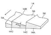
次に、樹脂材料14表面の他の凹凸パターン形状について説明する。図3は、成形後の樹脂材料14の端面14Aを直線状に切り取った状態の斜視図である。樹脂材料14の裏面は平面である。
Next, another uneven pattern shape on the surface of the
樹脂材料14の表面の凹凸パターン形状は、長手方向(図の矢印方向)の直線状の凹凸パターンである。この断面が鋸刃状パターンは、樹脂材料14の最厚肉部14Bと最薄肉部14Cとを繋ぐ鉛直壁54と、この鉛直壁54の上縁(最厚肉部14B)より樹脂材料14の最薄肉部14Cに向かって直線状に板厚が減少していくテーパ部56が繰り返される形状である。
The uneven pattern shape on the surface of the
図3において、樹脂材料14の最薄肉部14Cの厚さは、5mm以下であることが好ましく、2mm以上であることがより好ましい。樹脂材料14の最厚肉部14Bと最薄肉部14Cとの厚さの差は、1mm以上であることが好ましく、2.5mm以上であることがより好ましい。このような寸法とすることにより、各種表示装置の背面に配される導光板や各種光学素子に好適に使用できる。
In FIG. 3, the thickness of the
成形後の樹脂材料14を導光板に使用する場合には、鉛直壁54の側面に円柱状の冷陰極管が配され、この冷陰極管より照射される光線が、鉛直壁54の表面(側面)より樹脂材料14の内部に入射し、テーパ部56で反射し、樹脂材料14の裏面より面状に照射されることとなる。
When the molded
このように成形後の樹脂材料14を導光板に使用する場合には、テーパ部56傾斜角度θ3を3〜20度とするのが好ましい。
Thus, when using the
なお、成形後の樹脂材料14を導光板に使用する場合、これら以外の形状を採用することもできる。たとえば、図2の樹脂材料14のV溝50の断面形状はV字状となっているが、これ以外の形状、たとえば、矩形状、台形状、円弧状、放物線状等の断面形状も、光学的特性、成形性等を満足できれば採用できる。
In addition, when using the
また、型ローラ16表面の凹凸形状も、図2又は図3の樹脂材料14表面の反転形状である必要はなく、樹脂材料14の収縮代等を考慮して、樹脂材料14の製品形状が図2又は図3の形状となるように、この形状よりオフセットした形状とすることもできる。
Further, the uneven shape on the surface of the
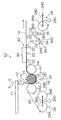
次に、本発明に係る樹脂シートの製造方法及び装置の他の実施の形態(第2実施形態)について詳説する。図4は、本発明に係る樹脂シートの製造方法が適用される、樹脂シートの製造ライン10’を示す構成図である。なお、図1に示される第1実施形態と同一、類似の部材については、同様の符号を附し、その説明を省略する。 Next, another embodiment (second embodiment) of the method and apparatus for producing a resin sheet according to the present invention will be described in detail. FIG. 4 is a configuration diagram showing a resin sheet production line 10 ′ to which the resin sheet production method according to the present invention is applied. In addition, the same code | symbol is attached | subjected about the member similar to 1st Embodiment shown by FIG. 1, and the description is abbreviate | omitted.
本実施形態においては、第1実施形態のニップローラ18の1ローラに代えて複数のニップローラ18(ニップローラ18A、ニップローラ18B、及びニップローラ18C)の3のローラが使用されている。
In the present embodiment, three rollers of a plurality of nip rollers 18 (nip
樹脂シートの製造ライン10’において、ニップローラ18Aは時計方向で9時の位置に、ニップローラ18Bは時計方向で7時の位置に、ニップローラ18Cは時計方向で5時の位置にそれぞれ配されており、それぞれ第1実施形態のニップローラ18と略同様の機能を果している。
In the resin sheet production line 10 ', the
ただし、3ローラであるので、挟圧する距離を大きくでき、所望の断面形状を容易に得ることができる構成となっている。また、ニップローラ18A、ニップローラ18B、及びニップローラ18Cを個別に駆動することにより、いわゆるドロー制御の運転方法が可能となる。
However, since there are three rollers, it is possible to increase the pinching distance and easily obtain a desired cross-sectional shape. In addition, by driving the
ニップローラ18(18A、18B、及び18C)に駆動手段を設ける場合に、それぞれの駆動速度を可変とする構成が好ましく採用できる。これにより、たとえば、ニップローラ18A、18B、18Cの順に、型ローラ16の周速より徐々に増速(せいぜい数%以内の範囲で)させる運転方法が採用できる。
When the driving means is provided in the nip roller 18 (18A, 18B, and 18C), a configuration in which each driving speed is variable can be preferably employed. Accordingly, for example, an operation method in which the
ニップローラ18A、18B、18Cには、いずれも、図示しない加圧手段が設けられており、型ローラ16との間の樹脂材料14を所定の圧力で挟圧できるようになっている。この加圧手段は、いずれも、ニップローラ18A、18B、18Cと型ローラ16との接触点における法線方向に圧力を印加する構成のもので、モータ駆動手段、エアシリンダ、油圧シリンダ等の公知の各種手段が採用できる。
Each of the
更に、図4の樹脂シートの製造ライン10’において、冷却装置38、40が設けられており、ニップローラ18A、18B、及び18Cの温度調節手段を補助する構成となっている。
Further, in the resin sheet production line 10 ′ of FIG. 4,
冷却装置38、40は、いずれもエアノズルであり、冷却装置38のエアノズルは、ニップローラ18Bとニップローラ18Cとの隙間より、搬送中の樹脂材料14とバックアップシート20との積層体にエアが吹き付けられるように配されており、冷却装置40のエアノズルは、ニップローラ18Cにエアが吹き付けられるように配されている。このようにして、直接樹脂材料14(積層体)の温度を制御するとともに、ニップローラ18Cを介して樹脂材料14(積層体)の温度を制御できるようになっている。
Each of the
冷却装置38、40のエア温度及びエア供給量(吹き付け流量)は、樹脂材料14の材質、樹脂材料14の溶融時(たとえば、ダイ12のスリット出口)の温度、樹脂材料14の搬送速度、型ローラ16の外径、型ローラ16の凹凸パターン形状、ニップローラ(ニップローラ18A、ニップローラ18B、及びニップローラ18C)の設定温度等によって最適な値を選択すべきである。
The air temperature and air supply amount (spraying flow rate) of the
一方、ニップローラ(ニップローラ18A、ニップローラ18B、及びニップローラ18C)の駆動は、ニップローラ18A、18B、18Cの順に、型ローラ16の周速より徐々に増速させる、いわゆるドロー制御の運転方法とする。ニップローラ18A、18B、18Cの各ローラ間のドロー値は、0〜3%とするのが好ましく、0〜1%とするのがより好ましい。
On the other hand, the driving of the nip rollers (nip
次に、図4に示される樹脂シートの製造ライン10’による樹脂シートの製造方法について説明する。 Next, a method for producing a resin sheet using the resin sheet production line 10 'shown in FIG. 4 will be described.
ダイ12より押し出したシート状の樹脂材料14と、シート繰り出し手段26より繰り出され、樹脂材料14の裏面に供給されたバックアップシート20との積層体を、型ローラ16と型ローラ16に対向配置されるニップローラ18A、18B、18Cとで順次挟圧し、型ローラ16表面の凹凸形状を樹脂材料14に転写し、樹脂材料14とバックアップシート20との積層体を型ローラ16に対向配置される剥離ローラ24に巻き掛けることにより型ローラ16より剥離する。
A laminated body of the sheet-
この際、型ローラ16とニップローラ18(18A、18B、18C)と剥離ローラ24の表面温度を、型ローラ16、ニップローラ18A、ニップローラ18B、ニップローラ18C、剥離ローラ24の順で低くなるように制御する。これにより、バックアップシート20の使用による効果と相俟って、各ローラからの樹脂材料14の剥離性が向上する。
At this time, the surface temperatures of the
この樹脂シートの製造において、ダイ12よりの樹脂材料14の押し出し速度は、0.1〜50m/分、好ましくは0.3〜30m/分の値が採用できる。したがって、型ローラ16の周速も略これに一致させる。
In the production of this resin sheet, the extrusion speed of the
一方、ニップローラ(ニップローラ18A、ニップローラ18B、及びニップローラ18C)の駆動は、ニップローラ18A、18B、18Cの順に、型ローラ16の周速より徐々に増速させる、いわゆるドロー制御の運転方法とする。ニップローラ18A、18B、18Cの各ローラ間のドロー値は、0〜3%とするのが好ましく、0〜1%とするのがより好ましい。
On the other hand, the driving of the nip rollers (nip
なお、各ローラの速度ムラは、設定値に対して1%以内になるように制御することが好ましい。 It should be noted that the speed unevenness of each roller is preferably controlled to be within 1% of the set value.
各ニップローラ(ニップローラ18A、ニップローラ18B、及びニップローラ18C)の型ローラ16への押し付け圧は、線圧換算(各ニップローラの弾性変形による面接触を線接触と仮定して換算した値)で、0〜200kN/m(0〜200kgf/cm)とするのが好ましく、0〜100kN/m(0〜100kgf/cm)とするのがより好ましい。
The pressing pressure of each nip roller (nip
ニップローラ18A、18B、18C、及び剥離ローラ24の温度制御は、既述したように、個々のローラ毎に行うことが好ましい。そして、剥離ローラ24の箇所における樹脂材料14が樹脂の軟化点Ta以下の温度になっていることが好ましい。この際、樹脂材料14にポリメチルメタクリレート樹脂を採用した場合、剥離ローラ24の設定温度は、50〜110°Cとできる。
As described above, the temperature control of the
型ローラ16より剥離した樹脂材料14を、水平方向に搬送し、徐冷ゾーン30を通過することにより徐冷し、歪みが除去された状態で、下流の製品取り部において所定長さに切断し、樹脂シートの製品として収容する。
The
次に、本発明に係る樹脂シートの製造方法及び装置の更に他の実施の形態(第3実施形態)について詳説する。図5は、本発明に係る樹脂シートの製造方法が適用される、樹脂シートの製造ライン10’’を示す構成図である。なお、図1に示される第1実施形態及び図4に示される第2実施形態と同一、類似の部材については、同様の符号を附し、その説明を省略する。 Next, still another embodiment (third embodiment) of the resin sheet manufacturing method and apparatus according to the present invention will be described in detail. FIG. 5 is a configuration diagram showing a resin sheet production line 10 ″ to which the resin sheet production method according to the present invention is applied. In addition, the same code | symbol is attached | subjected about the same and similar member as 1st Embodiment shown in FIG. 1, and 2nd Embodiment shown in FIG. 4, and the description is abbreviate | omitted.
本実施形態においては、第1、第2実施形態のシート繰り出し手段26及びシート巻回手段28等に代えて、シート循環手段26’が設けられている。このシート循環手段26’は、バックアップシート20をエンドレスベルトとし、循環使用させる手段である。
In the present embodiment, instead of the sheet feeding means 26 and the sheet winding means 28 of the first and second embodiments, a sheet circulation means 26 'is provided. The sheet circulation means 26 'is a means for circulating the
このシート循環手段26’は、シート駆動手段27とガイドローラ22とより構成される。シート駆動手段27は、ローラ27Aとローラ27Bとでバックアップシート20を挟み(ニップし)バックアップシート20を搬送させるための機構であり、ローラ27Aとローラ27Bの少なくとも1方が回転駆動されるようになっている。
The sheet circulation means 26 ′ is composed of a sheet driving means 27 and a
このシート循環手段26’において、バックアップシート20がエンドレスベルトとなっているので、バックアップシート20の搬送が容易となり、また、バックアップシート20の長さを短縮できる。また、シート繰り出し手段26及びシート巻回手段28等の組み合わせの構成よりもシート循環手段26’の構成が簡易となる。
In this sheet circulating means 26 ', the
このような樹脂シートの製造ライン10’’によっても、ライン条件や樹脂材料14の材質によっては良好な製品が製造できる。
Also with such a resin sheet production line 10 ″, a good product can be produced depending on the line conditions and the material of the
以上に説明した本発明に係る樹脂シートの製造方法及び装置(第1〜第3実施形態)によれば、成形時の幅方向の厚さ分布が大きい樹脂シートであっても、欠陥なく所望の断面形状を得ることができる。 According to the manufacturing method and apparatus (first to third embodiments) of the resin sheet according to the present invention described above, even if the resin sheet has a large thickness distribution in the width direction at the time of molding, it is desired without any defects. A cross-sectional shape can be obtained.
以上、本発明に係る樹脂シートの製造方法及び装置の実施形態について説明したが、本発明は上記実施形態に限定されるものではなく、各種の態様が採り得る。 As mentioned above, although embodiment of the manufacturing method and apparatus of the resin sheet which concern on this invention was described, this invention is not limited to the said embodiment, Various aspects can be taken.
たとえば、ニップローラの本数及び配置は、同様の機能が得られるのであれば、本実施形態以外の各種の態様が採り得る。 For example, the number and arrangement of the nip rollers may take various aspects other than the present embodiment as long as the same function can be obtained.
また、温度調節手段や、冷却装置(38等)、徐冷ゾーン30等についても、同様の機能が得られるのであれば、本実施形態以外の各種の態様が採り得る。
Further, the temperature adjusting means, the cooling device (38 and the like), the
以下、本発明の実施例及び比較例について説明する。 Examples of the present invention and comparative examples will be described below.
図1に示される樹脂シートの製造ライン10を使用して実施例及び比較例の樹脂シートを製造した。樹脂シートの断面形状は、図7に示される形状とした。Pは28mm、Wは4.2mm、Dは3.5mm、t1は1mm、t2は1.64mmとした。また、繰り返し単位の両端は斜面と接する円弧であり、その曲率Rは15mmとした。 The resin sheet of the Example and the comparative example was manufactured using the manufacturing line 10 of the resin sheet shown by FIG. The cross-sectional shape of the resin sheet was the shape shown in FIG. P was 28 mm, W was 4.2 mm, D was 3.5 mm, t1 was 1 mm, and t2 was 1.64 mm. Further, both ends of the repeating unit are arcs in contact with the slope, and the curvature R thereof is 15 mm.
型ローラ16とニップローラ18と剥離ローラ24の表面温度を以下のように設定し、実施例と比較例の樹脂シートを製造した。
The surface temperatures of the
実施例:型ローラ16とニップローラ18と剥離ローラ24の表面温度を、型ローラ16、ニップローラ18、剥離ローラ24の順で低くなるように制御した。実際のローラ温度(実測値)は、型ローラ16が90°Cであり、ニップローラ18が85°Cであり、剥離ローラ24が80°Cであった。
Example: The surface temperatures of the
比較例:型ローラ16とニップローラ18と剥離ローラ24の表面温度を、型ローラ16、ニップローラ18、剥離ローラ24の順で高くなるように制御した。実際のローラ温度(実測値)は、型ローラ16が85°Cであり、ニップローラ18が90°Cであり、剥離ローラ24が95°Cであった。
Comparative Example: The surface temperatures of the
実施例及び比較例に共通する製造条件は、以下のようにした。 Manufacturing conditions common to the examples and the comparative examples were as follows.
型ローラ16の周速度:1.3m/分
樹脂材料14の組成:PMMA(三菱レイヨン製VH001)
ダイ12の吐出口における樹脂材料14の温度:255°C
成形後の樹脂シートの評価は、500mm×500mmの大きさの板の反り量を評価した。
Peripheral speed of mold roller 16: 1.3 m / min Composition of resin material 14: PMMA (Mitsubishi Rayon VH001)
Temperature of the
Evaluation of the resin sheet after molding evaluated the amount of warpage of a plate having a size of 500 mm × 500 mm.
成形後の樹脂シートの評価結果は以下のようになった。 The evaluation results of the resin sheet after molding were as follows.
実施例:0.3mm/500mm
比較例:20mm/500mm
以上の比較結果より本発明の効果が確認できた。
Example: 0.3 mm / 500 mm
Comparative example: 20 mm / 500 mm
From the above comparison results, the effect of the present invention was confirmed.
10、10’、10’ ’…樹脂シートの製造ライン、12…ダイ、14…樹脂材料、16…型ローラ、18…ニップローラ、18A、18B、18C…ニップローラ、20…バックアップシート、22…ガイドローラ、24…剥離ローラ、26…シート繰り出し手段、28…シート巻回手段、30…徐冷ゾーン、38…冷却装置
10, 10 ', 10''... resin sheet production line, 12 ... die, 14 ... resin material, 16 ... mold roller, 18 ... nip roller, 18A, 18B, 18C ... nip roller, 20 ... backup sheet, 22 ... guide roller , 24 ... peeling roller, 26 ... sheet feeding means, 28 ... sheet winding means, 30 ... slow cooling zone, 38 ... cooling device
Claims (9)
該型ローラ表面の凹凸形状を前記樹脂材料に転写し、
転写後の前記樹脂材料と前記バックアップシートとの積層体を該型ローラに対向配置される剥離ローラに巻き掛けることにより該型ローラより剥離する樹脂シートの製造方法であって、
前記型ローラの温度を前記剥離ローラの温度よりも高く制御することを特徴とする樹脂シートの製造方法。 A sheet-shaped resin material extruded from a die and a backup sheet supplied to one side of the resin material are arranged such that the resin material is on the mold roller side and the backup sheet is on the nip roller side. Clamping with the nip roller disposed opposite the mold roller,
The uneven shape on the surface of the mold roller is transferred to the resin material,
A method for producing a resin sheet that is peeled off from a mold roller by winding a laminate of the resin material after transfer and the backup sheet on a peeling roller disposed to face the mold roller,
A method for producing a resin sheet, wherein the temperature of the mold roller is controlled to be higher than the temperature of the peeling roller.
シート状の樹脂材料を吐出口より押し出すダイと、
帯状可撓性のバックアップシートを供給するバックアップシート供給手段と、を備え、
前記ダイより押し出された樹脂材料が型ローラ側に、前記バックアップシートが前記ニップローラ側になるようにして、前記型ローラと前記ニップローラとで挟圧され、
該型ローラ表面の凹凸形状が前記樹脂材料に転写され、
転写後の前記樹脂材料と前記バックアップシートとの積層体が前記剥離ローラに巻き掛けられて該型ローラより剥離されることを特徴とする樹脂シートの製造装置。
A mold roller having a concavo-convex shape formed on a peripheral surface, a nip roller disposed opposite to one side of the mold roller, and a peeling roller disposed opposite to the other side of the mold roller, the mold roller, the nip roller, A roller array whose temperature is controlled so that the set temperature decreases in the order of the peeling roller;
A die for extruding a sheet-shaped resin material from the discharge port;
Backup sheet supply means for supplying a belt-like flexible backup sheet,
The resin material extruded from the die is sandwiched between the mold roller and the nip roller so that the backup sheet is on the nip roller side on the mold roller side,
The uneven shape on the surface of the mold roller is transferred to the resin material,
An apparatus for manufacturing a resin sheet, wherein a laminate of the resin material after transfer and the backup sheet is wound around the peeling roller and peeled off from the mold roller.
Priority Applications (1)
| Application Number | Priority Date | Filing Date | Title |
|---|---|---|---|
| JP2006092301A JP2007261202A (en) | 2006-03-29 | 2006-03-29 | Manufacturing method and apparatus for resin sheet |
Applications Claiming Priority (1)
| Application Number | Priority Date | Filing Date | Title |
|---|---|---|---|
| JP2006092301A JP2007261202A (en) | 2006-03-29 | 2006-03-29 | Manufacturing method and apparatus for resin sheet |
Publications (1)
| Publication Number | Publication Date |
|---|---|
| JP2007261202A true JP2007261202A (en) | 2007-10-11 |
Family
ID=38634655
Family Applications (1)
| Application Number | Title | Priority Date | Filing Date |
|---|---|---|---|
| JP2006092301A Pending JP2007261202A (en) | 2006-03-29 | 2006-03-29 | Manufacturing method and apparatus for resin sheet |
Country Status (1)
| Country | Link |
|---|---|
| JP (1) | JP2007261202A (en) |
Cited By (2)
| Publication number | Priority date | Publication date | Assignee | Title |
|---|---|---|---|---|
| JP2011102039A (en) * | 2008-12-17 | 2011-05-26 | Sharp Corp | Roller imprint device and method for producing imprint sheet |
| WO2019031159A1 (en) * | 2017-08-09 | 2019-02-14 | セーレン株式会社 | Embossing device and embossing method |
-
2006
- 2006-03-29 JP JP2006092301A patent/JP2007261202A/en active Pending
Cited By (7)
| Publication number | Priority date | Publication date | Assignee | Title |
|---|---|---|---|---|
| JP2011102039A (en) * | 2008-12-17 | 2011-05-26 | Sharp Corp | Roller imprint device and method for producing imprint sheet |
| WO2019031159A1 (en) * | 2017-08-09 | 2019-02-14 | セーレン株式会社 | Embossing device and embossing method |
| CN110914037A (en) * | 2017-08-09 | 2020-03-24 | 世联株式会社 | Embossing device and embossing method |
| JPWO2019031159A1 (en) * | 2017-08-09 | 2020-07-02 | セーレン株式会社 | Embossing device and embossing method |
| CN110914037B (en) * | 2017-08-09 | 2021-10-08 | 世联株式会社 | Embossing device and embossing method |
| JP7107941B2 (en) | 2017-08-09 | 2022-07-27 | セーレン株式会社 | Embossing device and embossing method |
| US11491699B2 (en) | 2017-08-09 | 2022-11-08 | Seiren Co., Ltd. | Emboss fabrication apparatus and emboss fabrication method |
Similar Documents
| Publication | Publication Date | Title |
|---|---|---|
| US20090014116A1 (en) | Method of producing resin sheet | |
| TWI379760B (en) | Apparatus for forming film with intermittent interval and method for forming film with intermittent interval | |
| US20100109185A1 (en) | Method and apparatus for manufacturing uneven thickness resin sheet | |
| JP2006056214A (en) | Manufacturing method of resin sheet | |
| JP2007216505A (en) | Manufacturing method and apparatus for resin sheet | |
| JP2008246866A (en) | Method and apparatus for producing particle-containing resin sheet | |
| US20080088052A1 (en) | Method Of Producing A Resin Sheet | |
| US20090071598A1 (en) | Method of producing resin sheet | |
| CN101646546A (en) | Method and apparatus for producing uneven thickness resin sheet | |
| JP2008080727A (en) | Manufacturing method of resin sheet | |
| JP2007216481A (en) | Manufacturing method and apparatus for resin sheet | |
| JP2006289968A (en) | Manufacturing method of resin sheet | |
| JP2006056220A (en) | Manufacturing method and apparatus for resin sheet | |
| JP2006256054A (en) | Manufacturing method of resin sheet | |
| JP4552716B2 (en) | Manufacturing method of resin sheet | |
| JP2008246867A (en) | Manufacturing method and apparatus for uneven thickness resin sheet | |
| JP2006256055A (en) | Manufacturing method of resin sheet | |
| JP2007210200A (en) | Manufacturing method of resin sheet | |
| JP2007210161A (en) | Manufacturing method and apparatus for resin sheet | |
| JP2006056215A (en) | Manufacturing method of resin sheet | |
| JP2006056219A (en) | Manufacturing method of resin sheet | |
| JP2006297910A (en) | Manufacturing method of resin sheet | |
| JP2006056217A (en) | Manufacturing method of resin sheet | |
| JP2007210160A (en) | Manufacturing method of resin sheet | |
| JP2006056216A (en) | Manufacturing method of resin sheet |