JP2007263360A - 軸受ユニット製造方法及び軸受ユニット - Google Patents
軸受ユニット製造方法及び軸受ユニット Download PDFInfo
- Publication number
- JP2007263360A JP2007263360A JP2006332794A JP2006332794A JP2007263360A JP 2007263360 A JP2007263360 A JP 2007263360A JP 2006332794 A JP2006332794 A JP 2006332794A JP 2006332794 A JP2006332794 A JP 2006332794A JP 2007263360 A JP2007263360 A JP 2007263360A
- Authority
- JP
- Japan
- Prior art keywords
- inner ring
- caulking
- pressing force
- bearing unit
- force acting
- Prior art date
- Legal status (The legal status is an assumption and is not a legal conclusion. Google has not performed a legal analysis and makes no representation as to the accuracy of the status listed.)
- Granted
Links
Images


Classifications
-
- F—MECHANICAL ENGINEERING; LIGHTING; HEATING; WEAPONS; BLASTING
- F16—ENGINEERING ELEMENTS AND UNITS; GENERAL MEASURES FOR PRODUCING AND MAINTAINING EFFECTIVE FUNCTIONING OF MACHINES OR INSTALLATIONS; THERMAL INSULATION IN GENERAL
- F16C—SHAFTS; FLEXIBLE SHAFTS; ELEMENTS OR CRANKSHAFT MECHANISMS; ROTARY BODIES OTHER THAN GEARING ELEMENTS; BEARINGS
- F16C43/00—Assembling bearings
- F16C43/04—Assembling rolling-contact bearings
-
- B—PERFORMING OPERATIONS; TRANSPORTING
- B21—MECHANICAL METAL-WORKING WITHOUT ESSENTIALLY REMOVING MATERIAL; PUNCHING METAL
- B21J—FORGING; HAMMERING; PRESSING METAL; RIVETING; FORGE FURNACES
- B21J9/00—Forging presses
- B21J9/02—Special design or construction
- B21J9/025—Special design or construction with rolling or wobbling dies
-
- B—PERFORMING OPERATIONS; TRANSPORTING
- B21—MECHANICAL METAL-WORKING WITHOUT ESSENTIALLY REMOVING MATERIAL; PUNCHING METAL
- B21K—MAKING FORGED OR PRESSED METAL PRODUCTS, e.g. HORSE-SHOES, RIVETS, BOLTS OR WHEELS
- B21K25/00—Uniting components to form integral members, e.g. turbine wheels and shafts, caulks with inserts, with or without shaping of the components
-
- F—MECHANICAL ENGINEERING; LIGHTING; HEATING; WEAPONS; BLASTING
- F16—ENGINEERING ELEMENTS AND UNITS; GENERAL MEASURES FOR PRODUCING AND MAINTAINING EFFECTIVE FUNCTIONING OF MACHINES OR INSTALLATIONS; THERMAL INSULATION IN GENERAL
- F16C—SHAFTS; FLEXIBLE SHAFTS; ELEMENTS OR CRANKSHAFT MECHANISMS; ROTARY BODIES OTHER THAN GEARING ELEMENTS; BEARINGS
- F16C19/00—Bearings with rolling contact, for exclusively rotary movement
- F16C19/02—Bearings with rolling contact, for exclusively rotary movement with bearing balls essentially of the same size in one or more circular rows
- F16C19/14—Bearings with rolling contact, for exclusively rotary movement with bearing balls essentially of the same size in one or more circular rows for both radial and axial load
- F16C19/18—Bearings with rolling contact, for exclusively rotary movement with bearing balls essentially of the same size in one or more circular rows for both radial and axial load with two or more rows of balls
- F16C19/181—Bearings with rolling contact, for exclusively rotary movement with bearing balls essentially of the same size in one or more circular rows for both radial and axial load with two or more rows of balls with angular contact
- F16C19/183—Bearings with rolling contact, for exclusively rotary movement with bearing balls essentially of the same size in one or more circular rows for both radial and axial load with two or more rows of balls with angular contact with two rows at opposite angles
- F16C19/184—Bearings with rolling contact, for exclusively rotary movement with bearing balls essentially of the same size in one or more circular rows for both radial and axial load with two or more rows of balls with angular contact with two rows at opposite angles in O-arrangement
- F16C19/186—Bearings with rolling contact, for exclusively rotary movement with bearing balls essentially of the same size in one or more circular rows for both radial and axial load with two or more rows of balls with angular contact with two rows at opposite angles in O-arrangement with three raceways provided integrally on parts other than race rings, e.g. third generation hubs
-
- F—MECHANICAL ENGINEERING; LIGHTING; HEATING; WEAPONS; BLASTING
- F16—ENGINEERING ELEMENTS AND UNITS; GENERAL MEASURES FOR PRODUCING AND MAINTAINING EFFECTIVE FUNCTIONING OF MACHINES OR INSTALLATIONS; THERMAL INSULATION IN GENERAL
- F16C—SHAFTS; FLEXIBLE SHAFTS; ELEMENTS OR CRANKSHAFT MECHANISMS; ROTARY BODIES OTHER THAN GEARING ELEMENTS; BEARINGS
- F16C2326/00—Articles relating to transporting
- F16C2326/01—Parts of vehicles in general
- F16C2326/02—Wheel hubs or castors
Landscapes
- Engineering & Computer Science (AREA)
- Mechanical Engineering (AREA)
- General Engineering & Computer Science (AREA)
- Mounting Of Bearings Or Others (AREA)
- Rolling Contact Bearings (AREA)
Abstract
【解決手段】外内輪間に複数の転動体を介挿した状態で、内輪構成体16を内輪4の軸方向端部側(車体側端部側)から嵌合させた後、加締め用治具の押圧力作用面22sを内輪の軸方向端部(車体側端部)4tに押し当てて押圧力を作用させ、当該軸方向端部の加締め領域12cを内輪構成体の周端面16sに沿って塑性変形させて加締めることで、内輪構成体を内輪に固定する加締め工程を有しており、当該加締め工程の開始に際し、内輪の軸方向端部には、少なくとも押圧力作用面に押し当てられる部位に、所定の曲率で凸状に連続した曲面形状を成す面取り部4Rが予め形成されている。
【選択図】図1
Description
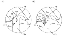
4 内輪
4R 面取り部
4t 軸方向端部(車体側端部)
6,8 転動体
12c 加締め領域
16 内輪構成体
16s 内輪構成体の周端面
22 加締め用治具(加締め金型)
22s 押圧力作用面
Claims (4)
- 相対回転可能に対向配置された外輪及び内輪と、内輪に固定可能な内輪構成体と、内輪構成体を内輪に固定することで所定の予圧が付与された状態で外内輪間に転動自在に組み込まれた複数の転動体とを備え、外輪及び内輪のいずれか一方が車体側に固定されて常時非回転状態に維持され、他方が車輪側に接続されて車輪と共に回転する軸受ユニットの製造方法であって、
外内輪間に複数の転動体を介挿した状態で、内輪構成体を内輪の軸方向端部側から嵌合させた後、加締め用治具の押圧力作用面を内輪の軸方向端部に押し当てて押圧力を作用させ、当該軸方向端部の加締め領域を内輪構成体の周端面に沿って塑性変形させて加締めることで、内輪構成体を内輪に固定する加締め工程を有しており、
当該加締め工程の開始に際し、内輪の軸方向端部には、少なくとも押圧力作用面に押し当てられる部位に、所定の曲率で凸状に連続した曲面形状を成す面取り部が予め形成されていることを特徴とする軸受ユニット製造方法。 - 面取り部は、軸方向端部の端面と当該端面の内周に沿って延出した側周面との間に連続して形成されており、少なくとも端面に連続する部分及び側周面に連続する部分が所定の曲率の凸状の曲面形状を成して形成されていることを特徴とする請求項1に記載の軸受ユニット製造方法。
- 面取り部は、その軸方向に沿った寸法をα、当該軸方向に直交した径方向に沿った寸法をβとすると、α>βなる関係を満足するように形成されていることを特徴とする請求項1又は2に記載の軸受ユニット製造方法。
- 請求項1〜3のいずれか1に記載の軸受ユニット製造方法により製造された軸受ユニット。
Priority Applications (1)
| Application Number | Priority Date | Filing Date | Title |
|---|---|---|---|
| JP2006332794A JP4779953B2 (ja) | 2006-03-02 | 2006-12-11 | 軸受ユニット製造方法及び軸受ユニット |
Applications Claiming Priority (3)
| Application Number | Priority Date | Filing Date | Title |
|---|---|---|---|
| JP2006056758 | 2006-03-02 | ||
| JP2006056758 | 2006-03-02 | ||
| JP2006332794A JP4779953B2 (ja) | 2006-03-02 | 2006-12-11 | 軸受ユニット製造方法及び軸受ユニット |
Publications (2)
| Publication Number | Publication Date |
|---|---|
| JP2007263360A true JP2007263360A (ja) | 2007-10-11 |
| JP4779953B2 JP4779953B2 (ja) | 2011-09-28 |
Family
ID=38636536
Family Applications (1)
| Application Number | Title | Priority Date | Filing Date |
|---|---|---|---|
| JP2006332794A Expired - Fee Related JP4779953B2 (ja) | 2006-03-02 | 2006-12-11 | 軸受ユニット製造方法及び軸受ユニット |
Country Status (1)
| Country | Link |
|---|---|
| JP (1) | JP4779953B2 (ja) |
Cited By (4)
| Publication number | Priority date | Publication date | Assignee | Title |
|---|---|---|---|---|
| WO2015190580A1 (ja) * | 2014-06-13 | 2015-12-17 | 日本精工株式会社 | 軸受装置及び軸受装置の製造方法 |
| US9481770B2 (en) | 2012-05-29 | 2016-11-01 | Toray Industries, Inc. | Carbon fiber composite material |
| JP7031802B1 (ja) * | 2020-09-24 | 2022-03-08 | 日本精工株式会社 | 軸受ユニット用のかしめ装置及びかしめ方法、ハブユニット軸受の製造方法及び製造装置、車両の製造方法 |
| CN115041918A (zh) * | 2021-03-09 | 2022-09-13 | 中央精机株式会社 | 用于制造车轮的方法 |
Citations (2)
| Publication number | Priority date | Publication date | Assignee | Title |
|---|---|---|---|---|
| JP2000087980A (ja) * | 1998-09-11 | 2000-03-28 | Koyo Seiko Co Ltd | 軸受装置 |
| JP2002139060A (ja) * | 2000-08-24 | 2002-05-17 | Ntn Corp | 車輪軸受装置 |
-
2006
- 2006-12-11 JP JP2006332794A patent/JP4779953B2/ja not_active Expired - Fee Related
Patent Citations (2)
| Publication number | Priority date | Publication date | Assignee | Title |
|---|---|---|---|---|
| JP2000087980A (ja) * | 1998-09-11 | 2000-03-28 | Koyo Seiko Co Ltd | 軸受装置 |
| JP2002139060A (ja) * | 2000-08-24 | 2002-05-17 | Ntn Corp | 車輪軸受装置 |
Cited By (9)
| Publication number | Priority date | Publication date | Assignee | Title |
|---|---|---|---|---|
| US9481770B2 (en) | 2012-05-29 | 2016-11-01 | Toray Industries, Inc. | Carbon fiber composite material |
| WO2015190580A1 (ja) * | 2014-06-13 | 2015-12-17 | 日本精工株式会社 | 軸受装置及び軸受装置の製造方法 |
| JPWO2015190580A1 (ja) * | 2014-06-13 | 2017-04-20 | 日本精工株式会社 | 軸受装置及び軸受装置の製造方法 |
| US10060472B2 (en) | 2014-06-13 | 2018-08-28 | Nsk Ltd. | Bearing device and method for manufacturing bearing device |
| JP7031802B1 (ja) * | 2020-09-24 | 2022-03-08 | 日本精工株式会社 | 軸受ユニット用のかしめ装置及びかしめ方法、ハブユニット軸受の製造方法及び製造装置、車両の製造方法 |
| WO2022064770A1 (ja) * | 2020-09-24 | 2022-03-31 | 日本精工株式会社 | 軸受ユニット用のかしめ装置及びかしめ方法、ハブユニット軸受の製造方法及び製造装置、車両の製造方法 |
| US12123466B2 (en) | 2020-09-24 | 2024-10-22 | Nsk Ltd. | Staking apparatus and staking method for bearing unit, manufacturing method and manufacturing apparatus of hub unit bearing, and manufacturing method of vehicle |
| CN115041918A (zh) * | 2021-03-09 | 2022-09-13 | 中央精机株式会社 | 用于制造车轮的方法 |
| CN115041918B (zh) * | 2021-03-09 | 2023-09-01 | 中央精机株式会社 | 用于制造车轮的方法 |
Also Published As
| Publication number | Publication date |
|---|---|
| JP4779953B2 (ja) | 2011-09-28 |
Similar Documents
| Publication | Publication Date | Title |
|---|---|---|
| JP5143455B2 (ja) | 駆動車輪用軸受装置 | |
| JP2007276780A (ja) | 車両用軸受装置 | |
| JP2008247316A (ja) | 車輪用転がり軸受装置及びその製造方法 | |
| JP6555426B2 (ja) | ハブユニット軸受およびその製造方法、並びに、自動車およびその製造方法 | |
| JP2011226576A (ja) | 密封シール付き転がり軸受ユニット | |
| JP4779953B2 (ja) | 軸受ユニット製造方法及び軸受ユニット | |
| US20050018937A1 (en) | Method of producing a holding collar with progressive transition | |
| JP4706242B2 (ja) | 転がり軸受装置の製造方法および転がり軸受装置 | |
| EP3327300A1 (en) | Bearing unit | |
| JP2007290681A (ja) | 駆動輪支持用ハブユニットとその製造方法 | |
| US20090268998A1 (en) | Wheel support bearing assembly | |
| JP2009058077A (ja) | 車輪用軸受装置 | |
| JP2009002480A (ja) | 車輪支持用転がり軸受ユニットの製造方法 | |
| JP2005024019A (ja) | 車輪用円すいころ軸受装置、およびその組立方法 | |
| JP4042528B2 (ja) | 転がり軸受装置 | |
| JP4543705B2 (ja) | 車輪用ハブユニット | |
| JP2002114004A (ja) | 車両用軸受装置 | |
| JP4538844B2 (ja) | 車輪用軸受装置 | |
| JP4899921B2 (ja) | 軸受組立方法 | |
| JP2003028150A (ja) | 軸受装置 | |
| JP2001315502A (ja) | 車両用ハブユニットおよびその製造方法 | |
| JP4798051B2 (ja) | 車輪用転がり軸受装置の組み付け方法 | |
| JP2008221337A (ja) | 車両用ハブユニットのかしめ方法 | |
| JP2005083496A (ja) | 車輪用の円すいころ軸受装置およびその組立方法 | |
| JP5283315B2 (ja) | 車輪用軸受装置 |
Legal Events
| Date | Code | Title | Description |
|---|---|---|---|
| A621 | Written request for application examination |
Free format text: JAPANESE INTERMEDIATE CODE: A621 Effective date: 20091207 |
|
| A131 | Notification of reasons for refusal |
Free format text: JAPANESE INTERMEDIATE CODE: A131 Effective date: 20110301 |
|
| A977 | Report on retrieval |
Free format text: JAPANESE INTERMEDIATE CODE: A971007 Effective date: 20110228 |
|
| A521 | Request for written amendment filed |
Free format text: JAPANESE INTERMEDIATE CODE: A523 Effective date: 20110406 |
|
| TRDD | Decision of grant or rejection written | ||
| A01 | Written decision to grant a patent or to grant a registration (utility model) |
Free format text: JAPANESE INTERMEDIATE CODE: A01 Effective date: 20110607 |
|
| A01 | Written decision to grant a patent or to grant a registration (utility model) |
Free format text: JAPANESE INTERMEDIATE CODE: A01 |
|
| A61 | First payment of annual fees (during grant procedure) |
Free format text: JAPANESE INTERMEDIATE CODE: A61 Effective date: 20110620 |
|
| FPAY | Renewal fee payment (event date is renewal date of database) |
Free format text: PAYMENT UNTIL: 20140715 Year of fee payment: 3 |
|
| R150 | Certificate of patent or registration of utility model |
Ref document number: 4779953 Country of ref document: JP Free format text: JAPANESE INTERMEDIATE CODE: R150 Free format text: JAPANESE INTERMEDIATE CODE: R150 |
|
| LAPS | Cancellation because of no payment of annual fees |