JP2007282920A - Portable surgical light - Google Patents
Portable surgical light Download PDFInfo
- Publication number
- JP2007282920A JP2007282920A JP2006114901A JP2006114901A JP2007282920A JP 2007282920 A JP2007282920 A JP 2007282920A JP 2006114901 A JP2006114901 A JP 2006114901A JP 2006114901 A JP2006114901 A JP 2006114901A JP 2007282920 A JP2007282920 A JP 2007282920A
- Authority
- JP
- Japan
- Prior art keywords
- light
- portable surgical
- portable
- bendable
- installation means
- Prior art date
- Legal status (The legal status is an assumption and is not a legal conclusion. Google has not performed a legal analysis and makes no representation as to the accuracy of the status listed.)
- Pending
Links
Images


Landscapes
- Non-Portable Lighting Devices Or Systems Thereof (AREA)
Abstract
Description
本発明は、持ち運び可能な携帯用無影灯に関する。 The present invention relates to a portable surgical light.
従来、持ち運び可能な携帯用無影灯としては術者の頭部に装着可能なものが知られている(例えば、特許文献1参照。)。 2. Description of the Related Art Conventionally, portable portable operating lamps that can be mounted on an operator's head are known (see, for example, Patent Document 1).
しかし、従来の携帯用無影灯は歯科治療用であって一つの光源を術者の頭部の前面に保持するのみであるから、術野を広く照明することができないという問題がある。また、術者の頭部以外の箇所には設置し得ないという問題がある。 However, since the conventional portable surgical lamp is used for dental treatment and only holds one light source on the front surface of the operator's head, there is a problem that the surgical field cannot be widely illuminated. In addition, there is a problem that it cannot be installed anywhere other than the operator's head.
したがって、本発明は上記不具合を解消することができる携帯用無影灯を提供することを目的とする。 Accordingly, an object of the present invention is to provide a portable surgical light that can eliminate the above-mentioned problems.
上記課題を解決するため、本発明は次のような構成を採用する。 In order to solve the above problems, the present invention employs the following configuration.
すなわち、請求項1に係る発明は、複数本の屈曲自在アーム(1a,1b,1c,1d)と、各屈曲自在アーム(1a,1b,1c,1d)の先端に取り付けられた光源(2a,2b,2c,2d)と、光源用の電源(3)と、全屈曲自在アーム(1a,1b,1c,1d)の末端が連結された基部(4,16)を所望箇所に設置する設置手段(9,14,15)とを具備した携帯用無影灯であることを特徴とする。 That is, the invention according to claim 1 includes a plurality of bendable arms (1a, 1b, 1c, 1d) and a light source (2a, 1b, 1d) attached to the tip of each bendable arm (1a, 1b, 1c, 1d). 2b, 2c, 2d), power source for light source (3), and base means (4, 16) to which the ends of all bendable arms (1a, 1b, 1c, 1d) are connected are installed at desired locations. (9, 14, 15) is a portable surgical light.
また、請求項2に係る発明は、請求項1に記載の携帯用無影灯において、上記設置手段が所望箇所を把持するクランプ具(9,15)であることを特徴とする。 The invention according to claim 2 is characterized in that, in the portable surgical light according to claim 1, the installation means is a clamp tool (9, 15) for gripping a desired location.
また、請求項3に係る発明は、請求項1又は請求項2に記載の携帯用無影灯において、上記設置手段が台車(14)であることを特徴とする。 According to a third aspect of the present invention, in the portable surgical light of the first or second aspect, the installation means is a carriage (14).
また、請求項4に係る発明は、請求項1乃至請求項3のいずれかに記載の携帯用無影灯において、上記基部が屈曲自在脚(4)であることを特徴とする。 According to a fourth aspect of the present invention, in the portable surgical light according to any one of the first to third aspects, the base is a bendable leg (4).
また、請求項5に係る発明は、請求項1乃至請求項4のいずれかに記載の携帯用無影灯において、上記電源(3)が基部(4,16)又は上記設置手段(9,14,15)に一体的に設けられたことを特徴とする。 According to a fifth aspect of the present invention, in the portable surgical light according to any one of the first to fourth aspects, the power source (3) is a base (4, 16) or the installation means (9, 14). , 15) are integrally provided.
また、請求項6に係る発明は、請求項1乃至請求項5のいずれかに記載の携帯用無影灯において、上記光源(2a,2b,2c,2d)に光拡散板(7)が取り付けられたことを特徴とする。
The invention according to
また、請求項7に係る発明は、請求項1乃至請求項6のいずれかに記載の携帯用無影灯において、上記基部が屈伸自在脚(16)で形成されたことを特徴とする。 According to a seventh aspect of the present invention, in the portable surgical lamp according to any one of the first to sixth aspects, the base portion is formed by a bendable / extendable leg (16).
また、請求項8に係る発明は、請求項1乃至請求項7のいずれかに記載の携帯用無影灯において、上記電源(3)がバッテリであることを特徴とする。
The invention according to
本発明によれば、複数本の屈曲自在アーム(1a,1b,1c,1d)と、各屈曲自在アーム(1a,1b,1c,1d)の先端に取り付けられた光源(2a,2b,2c,2d)と、光源用の電源(3)と、全屈曲自在アーム(1a,1b,1c,1d)の末端が連結された基部(4,16)を所望箇所に設置する設置手段(9,14,15)とを具備した携帯用無影灯であるから、屋内外の暗所において無影灯を簡易かつ迅速に設置し、無影灯が照明する領域を拡大し、術野を広く確保することができる。また、ベッド、床等所望の位置に設置することができる。また、屋外でカバン等を土台としその上に設置することも可能である。 According to the present invention, a plurality of bendable arms (1a, 1b, 1c, 1d) and a light source (2a, 2b, 2c, 1c) attached to the tip of each bendable arm (1a, 1b, 1c, 1d). 2d), a power source (3) for the light source, and an installation means (9, 14) for installing the bases (4, 16) to which the ends of all the bendable arms (1a, 1b, 1c, 1d) are connected at desired locations. , 15), it can be easily and quickly installed in indoor and outdoor dark places, expanding the area illuminated by the surgical light and ensuring a wide surgical field be able to. Moreover, it can install in desired positions, such as a bed and a floor. It is also possible to install a bag or the like on the base outdoors.
以下、図面を参照して発明を実施するための最良の形態について説明する。 The best mode for carrying out the invention will be described below with reference to the drawings.
<実施の形態1>
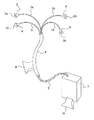
図1に示すように、この携帯用無影灯は、複数本の屈曲自在アーム1a,1b,1c,1dと、各屈曲自在アーム1a,1b,1c,1dの先端に取り付けられた光源2a,2b,2c,2dと、光源用の電源3と、全屈曲自在アーム1a,1b,1c,1dの末端が連結された基部を所望箇所に設置する設置手段とを具備する。
<Embodiment 1>
As shown in FIG. 1, this portable surgical lamp has a plurality of
屈曲自在アーム1a,1b,1c,1dは、自在に折り曲げることができるもので、所望の折り曲げ状態に折り曲げた後その状態に保持することができるようになっている。屈曲自在アーム1a,1b,1c,1dは望ましくはパイプ状であり、その中空内に電線5が通される。
The
光源2a,2b,2c,2dは、LED、電球等で構成される。この実施の形態1ではLEDが用いられる。各光源2a,2b,2c,2dの周りは望ましくは笠6で覆われる。笠6は略円錐形に形成され、上記各屈曲自在アーム1a,1b,1c,1dの先端に固定される。
The
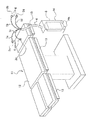
図2に示すように、各光源2a,2b,2c,2dには必要に応じて光拡散板7が設けられる。光拡散板7はポリカーボネート板等で作られ、笠6の前縁に連結具8で連結され固定される。各光源2a,2b,2c,2dからの光はこの光拡散板7により拡散された状態で患者の患部等に向って照射される。これにより、影が生じ難くなる。
As shown in FIG. 2, each
基部は、複数本の屈曲自在アーム1a,1b,1c,1dを束ねたものを保持するもので、この実施の形態1では屈曲自在脚4とされる。屈曲自在脚4は、例えば上記屈曲自在アーム1a,1b,1c,1dをより太くした構成であり、その先端に屈曲自在アーム1a,1b,1c,1dを束ねたものが連結される。また、各屈曲自在アーム1a,1b,1c,1d内に通された電線5が束になって通され、この電線5の束が基部4である屈曲自在脚4の末端から外部に引き出される。
The base holds a bundle of a plurality of
電源3としては、建屋等の定置式電源であってもよいが、望ましくは携帯可能なバッテリが用いられる。このバッテリに上記電線5の束が図示しない制御部を介して電気的に接続される。
The
設置手段は、具体的には固定手段であるクランプ具9である。クランプ具9としては公知の各種のものを使用することができるので、その詳しい説明は省略する。このクランプ具9が基部4である屈曲自在脚に取り付けられる。また、同様なクランプ具10が電源3であるバッテリにも取り付けられる。
The installation means is specifically a
図3に示すように、この携帯用無影灯は、例えば手術台11に取り付けられる。手術台11の患者が乗るテーブル12の周囲にはレール13が取り付けられているが、このレール13にクランプ具9,10によって基部である屈曲自在脚4と電源3であるバッテリがそれぞれ固定される。術者等が屈曲自在アーム1a,1b,1c,1dや屈曲自在脚4を所望の姿勢に屈曲させ、光源2a,2b,2c,2dの各々を望ましい向き及び位置にセットし、テーブル12上の図示しない患者の患部に複数条の光源光を照射する。これにより、病院等で停電が生じた場合であっても、迅速かつ簡易に無影灯を用意し、手術、治療等を適正に行うことができる。
As shown in FIG. 3, this portable surgical light is attached to an operating table 11, for example. A
<実施の形態2>
図4に示すように、この実施の形態2では、携帯用無影灯の設置手段が台車14とされる。この台車14の車輪14aにより携帯用無影灯は手術台11の近傍等所望の位置まで簡易に移動可能である。
<Embodiment 2>
As shown in FIG. 4, in this second embodiment, the portable operating light installation means is a
また、台車14には電源3であるバッテリが一体的に設けられる。
Further, a battery as a
なお、この実施の形態2において実施の形態1に示す部分と同じ部分には同一符号を用いて示すこととし、重複した説明を省略する。 In the second embodiment, the same parts as those shown in the first embodiment are denoted by the same reference numerals, and redundant description is omitted.
<実施の形態3>
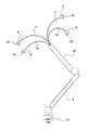
図5に示すように、この実施の形態3では、携帯用無影灯の基部が屈伸自在脚16とされる。この屈伸自在脚16の先端から光源2a,2b,2c,2dを保持する屈伸自在アーム1a,1b,1c,1dが突出し、屈伸自在脚16の末端にはクランプ具15が取り付けられる。屈伸自在脚16はクランプ具15により図4に示した手術台11のレール13その他所望の部位に固定される。
<
As shown in FIG. 5, in the third embodiment, the base portion of the portable surgical lamp is a
また、基部である屈伸自在脚16の所望位置には電源3であるバッテリが一体的に設けられる。
Further, a battery as the
なお、この実施の形態3において実施の形態1に示す部分と同じ部分には同一符号を用いて示すこととし、重複した説明を省略する。 In the third embodiment, the same parts as those shown in the first embodiment are denoted by the same reference numerals, and redundant description is omitted.
本発明は以上のように構成されるが、上記実施の形態に限定されるものではなく、その趣旨の範囲内において種々変更可能である。たとえば、上記実施の形態では光源、屈曲自在アームはそれぞれ4個ずつ設けているが、それ以上であってもよいし、2個ずつ又は3個ずつ設けてもよい。 Although the present invention is configured as described above, the present invention is not limited to the above-described embodiment, and various modifications can be made within the scope of the gist thereof. For example, in the above embodiment, four light sources and four bendable arms are provided, but the number may be more than that, or two or three may be provided.
1a,1b,1c,1d…屈曲自在アーム
2a,2b,2c,2d…光源
3…電源
4…屈曲自在脚
7…光拡散板
9,15…クランプ具
14…台車
16…屈伸自在脚
DESCRIPTION OF
Claims (8)
Priority Applications (1)
| Application Number | Priority Date | Filing Date | Title |
|---|---|---|---|
| JP2006114901A JP2007282920A (en) | 2006-04-18 | 2006-04-18 | Portable surgical light |
Applications Claiming Priority (1)
| Application Number | Priority Date | Filing Date | Title |
|---|---|---|---|
| JP2006114901A JP2007282920A (en) | 2006-04-18 | 2006-04-18 | Portable surgical light |
Publications (1)
| Publication Number | Publication Date |
|---|---|
| JP2007282920A true JP2007282920A (en) | 2007-11-01 |
Family
ID=38755217
Family Applications (1)
| Application Number | Title | Priority Date | Filing Date |
|---|---|---|---|
| JP2006114901A Pending JP2007282920A (en) | 2006-04-18 | 2006-04-18 | Portable surgical light |
Country Status (1)
| Country | Link |
|---|---|
| JP (1) | JP2007282920A (en) |
Cited By (7)
| Publication number | Priority date | Publication date | Assignee | Title |
|---|---|---|---|---|
| JP2011056225A (en) * | 2009-09-10 | 2011-03-24 | Sakamoto Kk | Lighting system for surgical operation |
| JP2012164612A (en) * | 2011-02-09 | 2012-08-30 | Motoki Terui | Portable medical lighting fixture |
| WO2013005186A1 (en) | 2011-07-06 | 2013-01-10 | Cabaud Francois | Surgical lighting assembly |
| JP2016217070A (en) * | 2015-05-25 | 2016-12-22 | 株式会社住軽日軽エンジニアリング | Ballast, fence, repair unit and repair method |
| KR101763513B1 (en) | 2016-01-20 | 2017-07-31 | 광주대학교산학협력단 | Field Emergency LED Surgical Light assembly of Easy Portable Type |
| US20180325617A1 (en) * | 2017-05-12 | 2018-11-15 | MezLight, LLC | Surgical light and uses thereof |
| US11478326B2 (en) | 2017-05-12 | 2022-10-25 | MezLight, LLC | Surgical light and uses thereof |
-
2006
- 2006-04-18 JP JP2006114901A patent/JP2007282920A/en active Pending
Cited By (7)
| Publication number | Priority date | Publication date | Assignee | Title |
|---|---|---|---|---|
| JP2011056225A (en) * | 2009-09-10 | 2011-03-24 | Sakamoto Kk | Lighting system for surgical operation |
| JP2012164612A (en) * | 2011-02-09 | 2012-08-30 | Motoki Terui | Portable medical lighting fixture |
| WO2013005186A1 (en) | 2011-07-06 | 2013-01-10 | Cabaud Francois | Surgical lighting assembly |
| JP2016217070A (en) * | 2015-05-25 | 2016-12-22 | 株式会社住軽日軽エンジニアリング | Ballast, fence, repair unit and repair method |
| KR101763513B1 (en) | 2016-01-20 | 2017-07-31 | 광주대학교산학협력단 | Field Emergency LED Surgical Light assembly of Easy Portable Type |
| US20180325617A1 (en) * | 2017-05-12 | 2018-11-15 | MezLight, LLC | Surgical light and uses thereof |
| US11478326B2 (en) | 2017-05-12 | 2022-10-25 | MezLight, LLC | Surgical light and uses thereof |
Similar Documents
| Publication | Publication Date | Title |
|---|---|---|
| JP4133834B2 (en) | Ambient lighting system for surgical light | |
| JP5911862B2 (en) | lamp | |
| JP4758660B2 (en) | Surgical lighting | |
| JP2017094126A (en) | Illumination attaching device for electrosurgical pencil and electrosurgical pencil fitting | |
| US20160022130A1 (en) | Track lighting system | |
| EP2916711B1 (en) | Intracavity illumination device | |
| JP2006236877A (en) | Illumination device | |
| JP6592242B2 (en) | Desktop lighting device for nail care | |
| JP2008034209A (en) | Local illumination device | |
| EP1757858A3 (en) | Illumination device with modular and movable lamp holder for display cabinets and/or display spaces | |
| JP2012164612A (en) | Portable medical lighting fixture | |
| JP5733808B2 (en) | Lighting device and desk lamp | |
| CN1287602A (en) | Lighting device | |
| JP5996866B2 (en) | Oral lighting | |
| JP3074919U (en) | Lighting equipment for power tools | |
| JP4402155B1 (en) | Ring light fixture | |
| JP2006337993A (en) | Magnifier and tools | |
| CN206608828U (en) | A kind of bent operation illuminating lamp | |
| ES1138861U (en) | Multipositional and multifunctional interactive table for cable placement and assembly of driver's beams. (Machine-translation by Google Translate, not legally binding) | |
| JP4359408B2 (en) | Lighting | |
| JP2011056225A (en) | Lighting system for surgical operation | |
| JP2008038306A (en) | Working glove improved in visibility | |
| CN211952500U (en) | Easy folding obstetrical department uses operating lamp | |
| JP2000207925A (en) | Desk lamp | |
| JP3062877U (en) | Flexible light-guiding tube structure |