JP2007282929A - Electric vacuum cleaner - Google Patents
Electric vacuum cleaner Download PDFInfo
- Publication number
- JP2007282929A JP2007282929A JP2006115084A JP2006115084A JP2007282929A JP 2007282929 A JP2007282929 A JP 2007282929A JP 2006115084 A JP2006115084 A JP 2006115084A JP 2006115084 A JP2006115084 A JP 2006115084A JP 2007282929 A JP2007282929 A JP 2007282929A
- Authority
- JP
- Japan
- Prior art keywords
- suction
- collection chamber
- cyclone dust
- dust collection
- vacuum cleaner
- Prior art date
- Legal status (The legal status is an assumption and is not a legal conclusion. Google has not performed a legal analysis and makes no representation as to the accuracy of the status listed.)
- Pending
Links
Images
Classifications
-
- A—HUMAN NECESSITIES
- A47—FURNITURE; DOMESTIC ARTICLES OR APPLIANCES; COFFEE MILLS; SPICE MILLS; SUCTION CLEANERS IN GENERAL
- A47L—DOMESTIC WASHING OR CLEANING; SUCTION CLEANERS IN GENERAL
- A47L9/00—Details or accessories of suction cleaners, e.g. mechanical means for controlling the suction or for effecting pulsating action; Storing devices specially adapted to suction cleaners or parts thereof; Carrying-vehicles specially adapted for suction cleaners
- A47L9/10—Filters; Dust separators; Dust removal; Automatic exchange of filters
- A47L9/106—Dust removal
- A47L9/108—Dust compression means
-
- A—HUMAN NECESSITIES
- A47—FURNITURE; DOMESTIC ARTICLES OR APPLIANCES; COFFEE MILLS; SPICE MILLS; SUCTION CLEANERS IN GENERAL
- A47L—DOMESTIC WASHING OR CLEANING; SUCTION CLEANERS IN GENERAL
- A47L9/00—Details or accessories of suction cleaners, e.g. mechanical means for controlling the suction or for effecting pulsating action; Storing devices specially adapted to suction cleaners or parts thereof; Carrying-vehicles specially adapted for suction cleaners
- A47L9/10—Filters; Dust separators; Dust removal; Automatic exchange of filters
- A47L9/16—Arrangement or disposition of cyclones or other devices with centrifugal action
- A47L9/1658—Construction of outlets
- A47L9/1666—Construction of outlets with filtering means
Landscapes
- Engineering & Computer Science (AREA)
- Mechanical Engineering (AREA)
- Filters For Electric Vacuum Cleaners (AREA)
Abstract
【課題】塵埃の圧縮を高めサイクロン集塵室を小型化することが可能な電気掃除機を提供する。
【解決手段】電気掃除機は、吸気口を有する吸込口体1と、吸気を発生させる電動送風機7と、吸込口体1と電動送風機7との間を連通する吸気通路と、吸気通路に配置され、流入する吸気を旋回させて塵埃を分離するサイクロン集塵室6とを備える。サイクロン集塵室6は、サイクロン集塵室内の上部に配置された第一の吸引部62と、サイクロン集塵室内の下部に配置された第二の吸引部64とを備える。
【選択図】図2A vacuum cleaner capable of increasing dust compression and reducing a cyclone dust collection chamber.
An electric vacuum cleaner is arranged in an intake port body having an intake port, an electric blower for generating intake air, an intake passage communicating between the intake port body and the electric blower, and an intake passage. And a cyclone dust collection chamber 6 for separating the dust by turning the inflowing intake air. The cyclone dust collection chamber 6 includes a first suction unit 62 disposed in the upper part of the cyclone dust collection chamber, and a second suction unit 64 disposed in the lower part of the cyclone dust collection chamber.
[Selection] Figure 2
Description
この発明は、一般的には電気掃除機に関し、特定的にはサイクロン集塵装置を備えた電気掃除機に関するものである。 The present invention generally relates to a vacuum cleaner, and more particularly to a vacuum cleaner equipped with a cyclone dust collector.
従来、サイクロン集塵装置を備えた電気掃除機においては、塵埃をダストカップ容器の中で高速に旋回させ、遠心力により分離している。 Conventionally, in a vacuum cleaner provided with a cyclone dust collector, dust is swirled at high speed in a dust cup container and separated by centrifugal force.
特開2002−51948号公報(特許文献1)には、フィルター下部に十字状のリブを設けた電気掃除機が記載されている。この掃除機では、旋回力で塵埃がフィルター下部の十字リブに衝突し、衝突の力で塵埃を圧縮している。 Japanese Patent Laying-Open No. 2002-51948 (Patent Document 1) describes a vacuum cleaner in which a cross-shaped rib is provided at the bottom of a filter. In this vacuum cleaner, dust collides with the cross rib at the bottom of the filter by the turning force, and the dust is compressed by the collision force.
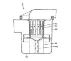
一例として、従来のサイクロン集塵室の概略的な全体の構成を図9に示す。 As an example, FIG. 9 shows a schematic overall configuration of a conventional cyclone dust collection chamber.
図9に示すように、大部分の塵埃はサイクロン集塵室6の吸引部62を覆うメッシュ状フィルター63からの吸引により遠心分離される。遠心分離された塵埃は、旋回力によって吸引部62下部のリブ構造体68の十字リブ68aに衝突し、衝突の力によって圧縮される。圧縮された塵埃は、サイクロン集塵室の一部としてのダストカップ60の底面61上に堆積する構造になっている。
しかしながら、旋回力だけでは圧縮力が弱いため、堆積された塵埃はダストカップ60の底面61上に十分に圧縮され得ない。このため、所定量の塵埃をダストカップ60内に堆積するためには、ある程度大きめのサイクロン集塵室が必要になる。
However, since the compression force is weak only by the turning force, the accumulated dust cannot be sufficiently compressed on the
そこで、この発明の目的は、塵埃の圧縮を高めサイクロン集塵室を小型化することが可能な電気掃除機を提供することである。 SUMMARY OF THE INVENTION An object of the present invention is to provide a vacuum cleaner capable of increasing dust compression and reducing the size of a cyclone dust collection chamber.
この発明に従った電気掃除機は、吸気口を有する吸込口体と、吸気を発生させる電動送風機と、吸込口体と電動送風機との間を連通する吸気通路と、吸気通路に配置され、流入する吸気を旋回させて塵埃を分離するサイクロン集塵室とを備える。サイクロン集塵室は、サイクロン集塵室内の上部に配置された第一の吸引部と、サイクロン集塵室内の下部に配置された第二の吸引部とを備える。 The vacuum cleaner according to the present invention is arranged in the intake passage, the suction port body having the intake port, the electric blower for generating intake air, the intake passage communicating between the suction port body and the electric blower, and the intake passage. And a cyclone dust collecting chamber for rotating the intake air to separate the dust. The cyclone dust collection chamber includes a first suction unit disposed at an upper portion in the cyclone dust collection chamber, and a second suction unit disposed at a lower portion in the cyclone dust collection chamber.
この発明の電気掃除機においては、吸気口体より取り込まれた吸気はサイクロン集塵室内に入ると、サイクロン集塵室内の上部にある第一の吸引部からの吸引によって旋回する。吸気の一部は、第一の吸引部を通って電動送風機側へと進む。吸気と共にサイクロン集塵室内に取り込まれた塵埃は旋回しながら遠心力によって分離され、下向きの旋回を与えられ、サイクロン集塵室内を下降する。下降した塵埃はサイクロン集塵室内の下部に堆積する。この時、サイクロン集塵室内の下部には第二の吸引部があり、この第二の吸引部の吸引によって、下降して堆積する塵埃を圧縮する。 In the vacuum cleaner according to the present invention, when the intake air taken in from the intake port body enters the cyclone dust collection chamber, the intake air swirls by suction from the first suction section at the top of the cyclone dust collection chamber. Part of the intake air proceeds to the electric blower side through the first suction part. The dust taken into the cyclone dust collection chamber together with the intake air is separated by centrifugal force while swirling, is given a downward swirling, and descends in the cyclone dust collecting chamber. The descending dust accumulates in the lower part of the cyclone dust chamber. At this time, there is a second suction part in the lower part of the cyclone dust collection chamber, and the dust that descends and accumulates is compressed by the suction of the second suction part.
このように、サイクロン集塵室内の上部と下部にふたつの吸引部を設けることにより、上部の第一の吸引部で塵埃を遠心分離し、下部の第二の吸引部で塵埃の圧縮を行うことができる。吸引による圧縮を行うことで、塵埃を旋回力で十字リブに衝突させて落下させて堆積させた場合よりも塵埃の体積を減少させることができる。 Thus, by providing two suction parts at the upper and lower parts in the cyclone dust collection chamber, the dust is centrifuged at the upper first suction part, and the dust is compressed at the lower second suction part. Can do. By performing the compression by suction, the volume of the dust can be reduced as compared with the case where the dust collides with the cross rib by a turning force and is dropped and accumulated.
この発明の電気掃除機においては、第一と第二の吸引部は、円筒面にメッシュ状のフィルターを含むことが好ましい。 In the electric vacuum cleaner of this invention, it is preferable that the 1st and 2nd attraction | suction part contains a mesh-like filter in a cylindrical surface.
この発明の電気掃除機においては、第二の吸引部の下面を吸引面とし、この吸引面とサイクロン集塵室の底面との間に空間を設けることが好ましい。 In the vacuum cleaner of this invention, it is preferable that the lower surface of the second suction portion is a suction surface, and a space is provided between the suction surface and the bottom surface of the cyclone dust collecting chamber.
このようにすることにより、塵埃の中で重めの砂ごみ系の堆積物がメッシュ状フィルターに触れるのを防止し、目詰まりを遅延させることができる。 By doing so, it is possible to prevent heavy sand dust deposits in the dust from touching the mesh filter and delay clogging.
この場合、さらにこの吸引面のサイクロン集塵室の底面側にリブを突出するように設けることが好ましい。 In this case, it is preferable to further provide a rib protruding from the bottom surface side of the cyclone dust collecting chamber on the suction surface.
このようにすることにより、紙ごみ等が第二の吸引部のメッシュ状フィルターに密着することを防ぎ、吸引力を保つことができる。 By doing in this way, it can prevent paper dust etc. sticking to the mesh filter of the 2nd suction part, and can maintain suction power.
またこの場合、第二の吸引部は、吸引面に配置されたメッシュ状のフィルターとスポンジ状のフィルターとを含むことが好ましい。 In this case, the second suction part preferably includes a mesh-like filter and a sponge-like filter arranged on the suction surface.
このようにすることにより、微細塵による目詰まりを遅延させることができる。 By doing so, clogging due to fine dust can be delayed.
さらにこの場合、このスポンジ状フィルターの下面と、さらに側面から吸引することが好ましい。 Further, in this case, it is preferable to suck from the lower surface and further the side surface of the sponge filter.
このようにすることにより、吸引面積を増大させ、微細塵による目詰まりをさらに遅延させることができる。 By doing so, the suction area can be increased, and clogging due to fine dust can be further delayed.
以上のように、この発明によれば、吸引によって塵埃の圧縮を高めることができ、サイクロン集塵室を小型化することができる。 As described above, according to the present invention, dust compression can be enhanced by suction, and the cyclone dust collection chamber can be downsized.
以下、この発明の実施の形態を図面に基づいて説明する。 Hereinafter, embodiments of the present invention will be described with reference to the drawings.
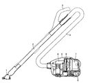
図1は、この発明の一つの実施の形態として、サイクロン集塵室を備えた電気掃除機全体の概略断面図である。 FIG. 1 is a schematic cross-sectional view of an entire electric vacuum cleaner provided with a cyclone dust collection chamber as one embodiment of the present invention.
図1に示すように、本発明の電気掃除機は、吸気口体1と、延長管2と、ハンドル3と、ホース4と、掃除機本体5と、サイクロン集塵室6と、電動送風機7と、コードリール8と、電動送風機前フィルター9とを備える。延長管2とホース4は、吸気口体1から吸引された空気を掃除機本体5に供給するための供給路(吸気通路)を構成する。吸気口体1は電動送風機7の運転により、空気吸込口(図示しない)を介して空気を吸引する。吸気口体1から吸引された塵埃は延長管2、ホース4からサイクロン集塵室6に入る。
As shown in FIG. 1, the vacuum cleaner of the present invention includes an air inlet body 1, an extension pipe 2, a handle 3, a hose 4, a cleaner body 5, a cyclone
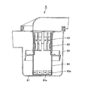
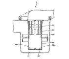
図2は、本発明の一つの実施の形態として図1の電気掃除機に組み込まれるサイクロン集塵室の概略的な全体の構成を示す図である。 FIG. 2 is a diagram showing a schematic overall configuration of a cyclone dust collection chamber incorporated in the electric vacuum cleaner of FIG. 1 as one embodiment of the present invention.
図2に示すように、サイクロン集塵室6の上部に第一の吸引部62と、第一の吸引部62より下方に第二の吸引部64を設けている。第一の吸引部62は円筒形で、円筒面にはメッシュ状フィルター63が一定の間隔をおいて配置されている。第二の吸引部64も円筒形であり、円筒面にはメッシュ状フィルター65aが一定の間隔をおいて配置されている。第二の吸引部64の底部64aは、ダストカップ60の底面61に接している。
As shown in FIG. 2, a
主として第一の吸引部62で遠心分離を行うための吸引を行い、第二の吸引部64でごみを圧縮するための吸引を行う。すなわち、サイクロン集塵室内6に取り込まれた吸気は、第一の吸引部62の吸引により旋回し、塵埃が遠心分離される。遠心分離された塵埃は、下向きの旋回を与えられ、ダストカップ60中を下降する。ダストカップ60の下部には第二の吸引部64が配置されており、第二の吸引部64の吸引によって塵埃が圧縮され、ダストカップ60内に堆積する。塵埃の中で特に綿ごみは、約1/3程度圧縮することができる。
The
なお、第二の吸引部は第一の吸引部の延長上に設けることで、従来のサイクロン集塵装置を備えた電気掃除機にごみ圧縮機能を付加することができる。 In addition, a dust suction function can be added to the electric vacuum cleaner provided with the conventional cyclone dust collector by providing the 2nd suction part on extension of the 1st suction part.
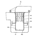
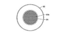
図3は本発明のもう一つの実施の形態として、サイクロン集塵室の概略的な全体の構成を示す図、図4は図3に示される第二の吸引部の吸引面を下から見た図である。 FIG. 3 is a diagram showing a schematic overall configuration of a cyclone dust collection chamber as another embodiment of the present invention, and FIG. 4 is a view of the suction surface of the second suction unit shown in FIG. FIG.
図3と図4に示すように、円筒形をした第二の吸引部64の底面には開口64bが形成されている。開口64bはメッシュ状フィルター65bで覆われている。メッシュ状フィルター65bとダストカップ60の底面61との間には空間を設けている。このため、ごみの中でも重い砂ごみ系がダストカップ60の底面上に堆積したときに、この堆積物がメッシュ状フィルター65bに触れるのを遅らせ、メッシュ状フィルター65bの目詰まり防ぐことができる。このようにすることにより、吸引力を保ち、塵埃の圧縮を持続できる。
As shown in FIGS. 3 and 4, an
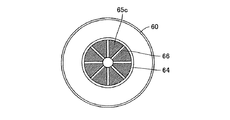
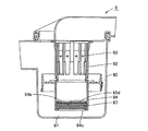
図5は、本発明のさらにもうひとつの実施の形態として、サイクロン集塵室の概略的な全体の構成を示す図、図6は、図5に示す第二の吸引部の吸引面を下から見た図である。 FIG. 5 is a diagram showing a schematic overall configuration of a cyclone dust collection chamber as still another embodiment of the present invention, and FIG. 6 is a view of the suction surface of the second suction unit shown in FIG. FIG.
図5と図6に示すように、円筒形をした第二の吸引部の底面には開口64bが形成されている。開口64bはメッシュ状フィルター65cで覆われている。ダストカップ60の底面61とメッシュ状フィルター65cとの間に空間を設けるとともに、リブ66はサイクロン集塵室6の底面側に突出するように、第二の吸引部64の吸引面に設けられている。このように構成されているので、紙ごみ等の密着による吸引力の低下を防ぐことができる。従って吸引力を保ち、塵埃の圧縮を持続できる。なお図6ではリブの配置の一例として、複数のリブ66は吸引面の中心から放射状に延びるように設けられている。
As shown in FIGS. 5 and 6, an opening 64b is formed on the bottom surface of the cylindrical second suction part. The opening 64b is covered with a
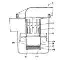
図7は、本発明のさらに別の実施の形態として、サイクロン集塵室の概略的な全体の構成を示す図である。 FIG. 7 is a diagram showing a schematic overall configuration of a cyclone dust collection chamber as still another embodiment of the present invention.
図7に示すように、円筒形の第二の吸引部64の底面には開口64bが形成されている。開口64bはメッシュ状フィルター65dで覆われ、さらにその下にスポンジ状フィルター67が設けられている。スポンジ状フィルター67とダストカップ60の底面61との間には空間を設ける。スポンジ状フィルター67の下面を露出するように、穴64cが第二の吸引部64に形成されている。吸引は穴64cを通じて行う。スポンジ状フィルター67を設けることにより、メッシュ状フィルター65dのみを設けた場合よりも微細塵の目詰まりを遅延させることができる。これにより吸引力を保つとともに、塵埃の圧縮を持続できる。なお、スポンジ状フィルター67は着脱可能である。したがってスポンジ状フィルター67をサイクロン集塵室6より取り外して清掃することができる。その結果スポンジ状フィルター67を清掃することで吸引力を保ち、塵埃の圧縮を持続させることができる。
As shown in FIG. 7, an
図8は、さらにまた別の実施の形態として、サイクロン集塵室の概略的な全体の構成を示す図である。 FIG. 8 is a diagram showing a schematic overall configuration of a cyclone dust collection chamber as still another embodiment.
図8に示すように、円筒形の第二の吸引部64の底面には開口64bが形成されている。開口64bはメッシュ状フィルター65dで覆われ、さらにその下にスポンジ状フィルター67が設けられている。スポンジ状フィルター67とダストカップ60の底面61との間には空間を設ける。スポンジ状フィルター67の下面を露出するように、穴64cが第二の吸引部64に形成されている。また、スポンジ状フィルターの側面を露出するように、第二の吸引部64の側面に穴64dが形成されている。第二の吸引部64による吸引は、スポンジ状フィルター67の一部を露出する穴64cと側面の一部を露出する穴64dとを通じて2方向で行う。このようにして吸引面積を増大させることで、塵埃の圧縮効率が向上する。なお、スポンジ状フィルター67は着脱可能である。したがってスポンジ状フィルター67をサイクロン集塵室6より取り外して清掃することができる。その結果スポンジ状フィルター67を清掃することで吸引力を保ち、塵埃の圧縮を持続させることができる。
As shown in FIG. 8, an
以上に開示された実施の形態はすべての点で例示であって制限的なものではないと考慮されるべきである。本発明の範囲は、以上の実施の形態ではなく、特許請求の範囲によって示され、特許請求の範囲と均等の意味および範囲内でのすべての修正や変形を含むものである。 The embodiment disclosed above should be considered as illustrative in all points and not restrictive. The scope of the present invention is shown not by the above embodiments but by the scope of claims, and includes all modifications and variations within the meaning and scope equivalent to the scope of claims.
1:吸気口体、2:延長管、4:ホース、6:サイクロン集塵室、7:電動送風機、60:ダストカップ、61:底面、62:第一の吸引部、63:メッシュ状フィルター、64:第二の吸引部、64c,64d:開口、65c、65d:メッシュ状フィルター、66:リブ、67:スポンジ状フィルター。 1: intake port body, 2: extension pipe, 4: hose, 6: cyclone dust collecting chamber, 7: electric blower, 60: dust cup, 61: bottom surface, 62: first suction part, 63: mesh filter, 64: second suction part, 64c, 64d: opening, 65c, 65d: mesh filter, 66: rib, 67: sponge filter.
Claims (6)
吸気を発生させる電動送風機と、
前記吸込口体と前記電動送風機との間を連通する吸気通路と、
前記吸気通路に配置され、流入する吸気を旋回させて塵埃を分離するサイクロン集塵室とを備え、
前記サイクロン集塵室は、前記サイクロン集塵室内の上部に配置された第一の吸引部と、前記サイクロン集塵室内の下部に配置された第二の吸引部とを含む、電気掃除機。 A suction port body having an intake port;
An electric blower that generates intake air;
An intake passage communicating between the suction port body and the electric blower;
A cyclone dust collection chamber disposed in the intake passage and configured to separate dust by swirling inflowing intake air;
The cyclone dust collection chamber is an electric vacuum cleaner including a first suction unit disposed at an upper part of the cyclone dust collection chamber and a second suction unit disposed at a lower part of the cyclone dust collection chamber.
Priority Applications (1)
| Application Number | Priority Date | Filing Date | Title |
|---|---|---|---|
| JP2006115084A JP2007282929A (en) | 2006-04-19 | 2006-04-19 | Electric vacuum cleaner |
Applications Claiming Priority (1)
| Application Number | Priority Date | Filing Date | Title |
|---|---|---|---|
| JP2006115084A JP2007282929A (en) | 2006-04-19 | 2006-04-19 | Electric vacuum cleaner |
Publications (1)
| Publication Number | Publication Date |
|---|---|
| JP2007282929A true JP2007282929A (en) | 2007-11-01 |
Family
ID=38755226
Family Applications (1)
| Application Number | Title | Priority Date | Filing Date |
|---|---|---|---|
| JP2006115084A Pending JP2007282929A (en) | 2006-04-19 | 2006-04-19 | Electric vacuum cleaner |
Country Status (1)
| Country | Link |
|---|---|
| JP (1) | JP2007282929A (en) |
Cited By (5)
| Publication number | Priority date | Publication date | Assignee | Title |
|---|---|---|---|---|
| JP2010268876A (en) * | 2009-05-20 | 2010-12-02 | Panasonic Corp | Dust collector and vacuum cleaner |
| JP2011255196A (en) * | 2011-08-15 | 2011-12-22 | Hitachi Appliances Inc | Vacuum cleaner |
| WO2012176349A1 (en) * | 2011-06-24 | 2012-12-27 | 株式会社東芝 | Electric vacuum cleaner |
| JP2016147187A (en) * | 2016-05-26 | 2016-08-18 | シャープ株式会社 | Cyclone separator, vacuum cleaner |
| JP2022139605A (en) * | 2021-03-12 | 2022-09-26 | パナソニックIpマネジメント株式会社 | Cyclone type cleaner |
-
2006
- 2006-04-19 JP JP2006115084A patent/JP2007282929A/en active Pending
Cited By (11)
| Publication number | Priority date | Publication date | Assignee | Title |
|---|---|---|---|---|
| JP2010268876A (en) * | 2009-05-20 | 2010-12-02 | Panasonic Corp | Dust collector and vacuum cleaner |
| WO2012176349A1 (en) * | 2011-06-24 | 2012-12-27 | 株式会社東芝 | Electric vacuum cleaner |
| JP2013005921A (en) * | 2011-06-24 | 2013-01-10 | Toshiba Corp | Electric vacuum cleaner |
| CN103648348A (en) * | 2011-06-24 | 2014-03-19 | 株式会社东芝 | Electric vacuum cleaner |
| KR101390549B1 (en) * | 2011-06-24 | 2014-04-30 | 가부시끼가이샤 도시바 | Vacuum cleaner |
| EP2724654A4 (en) * | 2011-06-24 | 2015-02-18 | Toshiba Kk | ELECTRICAL VACUUM |
| CN103648348B (en) * | 2011-06-24 | 2017-03-08 | 东芝生活电器株式会社 | Electric dust collector |
| JP2011255196A (en) * | 2011-08-15 | 2011-12-22 | Hitachi Appliances Inc | Vacuum cleaner |
| JP2016147187A (en) * | 2016-05-26 | 2016-08-18 | シャープ株式会社 | Cyclone separator, vacuum cleaner |
| JP2022139605A (en) * | 2021-03-12 | 2022-09-26 | パナソニックIpマネジメント株式会社 | Cyclone type cleaner |
| JP7607216B2 (en) | 2021-03-12 | 2024-12-27 | パナソニックIpマネジメント株式会社 | Cyclone vacuum cleaner |
Similar Documents
| Publication | Publication Date | Title |
|---|---|---|
| US9226631B2 (en) | Cyclone separator and vacuum cleaner | |
| JP3699679B2 (en) | Vacuum cleaner | |
| US7128770B2 (en) | Cyclone dust-collector | |
| CA2535388C (en) | Subsection dedusting device for a vacuum cleaner | |
| EP3537943B1 (en) | Vacuum cleaner | |
| JP2006175423A (en) | Grille member, and cyclone dust-collecting apparatus and vacuum cleaner provided with the same | |
| JP2007275591A (en) | Vacuum cleaner dust collector | |
| JP2004344642A (en) | Double cyclone dust collector for vacuum cleaner | |
| JP2004321777A (en) | Cyclone dust collector for vacuum cleaner | |
| GB2418162A (en) | Cyclonic dust collecting apparatus. | |
| JP2011041766A (en) | Vacuum cleaner | |
| JP4169735B2 (en) | Vacuum cleaner | |
| JP2003310502A (en) | Electric vacuum cleaner | |
| JP5905748B2 (en) | Cyclone separation device and vacuum cleaner | |
| US20050268428A1 (en) | Cyclone type dirt separator and electric vacuum cleaner | |
| JP2007282929A (en) | Electric vacuum cleaner | |
| CN202537412U (en) | Multi-cyclone dust removal device for vacuum dust collector | |
| JP2011142936A (en) | Cyclone dust collector and vacuum cleaner with the same | |
| JP2004215760A (en) | Electric vacuum cleaner | |
| JP4195982B2 (en) | Vacuum cleaner | |
| JP3821100B2 (en) | Vacuum cleaner | |
| JP4322257B2 (en) | Garbage separator | |
| JP2006255253A (en) | Electric vacuum cleaner | |
| JP3905046B2 (en) | Electric vacuum cleaner | |
| JP2011161003A (en) | Vacuum cleaner |