JP2007284902A - Steel pipe press-fit assisting device and steel pipe press-fitting method using the same - Google Patents
Steel pipe press-fit assisting device and steel pipe press-fitting method using the same Download PDFInfo
- Publication number
- JP2007284902A JP2007284902A JP2006110627A JP2006110627A JP2007284902A JP 2007284902 A JP2007284902 A JP 2007284902A JP 2006110627 A JP2006110627 A JP 2006110627A JP 2006110627 A JP2006110627 A JP 2006110627A JP 2007284902 A JP2007284902 A JP 2007284902A
- Authority
- JP
- Japan
- Prior art keywords
- steel pipe
- press
- casing
- auxiliary device
- fitting
- Prior art date
- Legal status (The legal status is an assumption and is not a legal conclusion. Google has not performed a legal analysis and makes no representation as to the accuracy of the status listed.)
- Pending
Links
- 229910000831 Steel Inorganic materials 0.000 title claims abstract description 171
- 239000010959 steel Substances 0.000 title claims abstract description 171
- 238000000034 method Methods 0.000 title claims abstract description 14
- 230000002093 peripheral effect Effects 0.000 claims abstract description 28
- 239000011435 rock Substances 0.000 claims abstract description 26
- 238000009412 basement excavation Methods 0.000 claims description 16
- 238000010276 construction Methods 0.000 description 8
- 239000007787 solid Substances 0.000 description 3
- 239000000725 suspension Substances 0.000 description 3
- 239000000470 constituent Substances 0.000 description 2
- 238000007796 conventional method Methods 0.000 description 2
- 230000000694 effects Effects 0.000 description 2
- 238000012986 modification Methods 0.000 description 2
- 230000004048 modification Effects 0.000 description 2
- 238000003466 welding Methods 0.000 description 2
Images



Landscapes
- Placing Or Removing Of Piles Or Sheet Piles, Or Accessories Thereof (AREA)
- Earth Drilling (AREA)
- Bulkheads Adapted To Foundation Construction (AREA)
Abstract
Description
本発明は、主に建設工事の基礎工事等を行う場合に鋼管矢板等の鋼管を杭圧入機を用いて地盤や岩盤に圧入する際に使用される鋼管圧入補助装置及びそれを使用した鋼管圧入工法に関する。 The present invention mainly relates to a steel pipe press auxiliary device used when pressing steel pipes such as steel pipe sheet piles into the ground or rock using a pile press machine when performing foundation work of construction work, and steel pipe press fitting using the same. Concerning construction method.
建設現場の基礎工事等においては鋼管としての鋼管矢板を油圧式杭圧入機で地盤や岩盤に圧入して埋設する場合がある。
この場合、鋼管矢板を圧入する地盤が固い地盤であったり岩盤であったりすると油圧式杭圧入機だけの圧入作業だけでは鋼管矢板を地盤や岩盤に圧入するのが極めて困難になる場合がある。
そこで、先端部にアースオーガを取り付けたクレーンを搭載してなる穴掘建柱車(特許文献1)を使用して、前記アースオーガーのオーガスクリューで固い地盤や岩盤を掘削してから油圧式杭圧入機を使用して鋼管矢板を圧入する工法が提案されている。
しかし、前記穴掘建柱車は搭載したクレーンの先端部にアースオーガを回動可能に取り付けた構造であるため掘削作業の作業半径が小さく、掘削場所の近くに穴掘建柱車を配置しないと垂直状態で地盤や岩盤を掘削することができない。
このため、掘削場所の近くに前記穴掘建柱車を配置するための堅固な作業構台を建設現場に設ける必要がある。また、掘削した後に鋼管矢板を圧入していくと掘削場所の近くに前記穴掘建柱車を配置するための堅固な作業構台を順次設ける必要がある。従って、前記作業構台の構築及び作業構台の取り壊し等の煩雑な作業が別途必要になるという不具合がある。
そこで、アースオーガをクレーンで垂直状に吊り下げ、吊り下げたアースオーガのオーガスクリューを鋼管矢板に挿通して鋼管矢板の内側を垂直状に掘削しながら油圧式杭圧入機を使用して鋼管矢板を圧入する工法が提案されている。
しかし、この場合、掘削する地盤や岩盤の固さ条件等によっては掘削時にオーガスクリューが受ける摩擦抵抗が大きくなり摩擦抵抗がクレーンに垂直状に吊り下げられているアースオーガに伝わり、これによりアースオーガのモータ自体が回ってしまってモータの駆動力がオーガスクリューに伝わり難くなってオーガスクリューによる円滑な掘削が困難になる場合がある。
In this case, if the ground into which the steel pipe sheet pile is pressed is a hard ground or a rock, it may be extremely difficult to press the steel pipe sheet pile into the ground or the bedrock only by a press-fitting operation using only a hydraulic pile press.
Therefore, a hydraulic pile is used after excavating a hard ground or rock mass with an auger screw of the earth auger using a digging pillar car (Patent Document 1) equipped with a crane having an earth auger attached to the tip. A construction method in which a steel pipe sheet pile is press-fitted using a press-fitting machine has been proposed.
However, since the digging column car has a structure in which an earth auger is rotatably attached to the tip of the mounted crane, the working radius of the digging work is small, and no digging column car is arranged near the excavation site It is impossible to excavate the ground or rock in a vertical state.
For this reason, it is necessary to provide a solid work gantry on the construction site for disposing the digging column car near the excavation site. In addition, when a steel pipe sheet pile is press-fitted after excavation, it is necessary to sequentially provide a solid work gantry for arranging the digging column car near the excavation site. Therefore, there is a problem that complicated work such as construction of the work gantry and demolition of the work gantry is required separately.
Therefore, the earth auger was suspended vertically with a crane, and the auger screw of the suspended earth auger was inserted into the steel pipe sheet pile to excavate the inside of the steel pipe sheet pile vertically, using a steel pile sheet pile using a hydraulic pile presser A method of press-fitting is proposed.
In this case, however, the frictional resistance that the auger screw receives during excavation increases depending on the hardness conditions of the ground and bedrock to be excavated, and the frictional resistance is transmitted to the earth auger that is suspended vertically from the crane. The motor itself rotates and the driving force of the motor becomes difficult to be transmitted to the auger screw, and smooth excavation by the auger screw may be difficult.
本発明は、上記事実に鑑みなされたものであり掘削場所近くに堅固な作業構台を構築しなくても固い地盤や岩盤をオーガスクリューで円滑に掘削できるようにすることにより杭圧入機で鋼管矢板等の鋼管を円滑に圧入することができる鋼管圧入補助装置及びそれを使用した鋼管圧入工法を提供するものである。 The present invention has been made in view of the above-mentioned facts, and it is possible to smoothly excavate hard ground or rock with an auger screw without constructing a solid work gantry near the excavation site. A steel pipe press-fitting auxiliary device capable of smoothly press-fitting a steel pipe such as a steel pipe and a steel pipe press-fitting method using the same.
請求項1の発明は、杭圧入機で鋼管を地盤や岩盤に圧入する場合に使用される鋼管圧入補助装置であって、吊り下げられた状態で前記鋼管に挿入可能に形成されたケーシングと、このケーシングに固定されたアースオーガのモータと、前記ケーシングに挿通されて先端部がケーシングの下端面より突出するように配設された前記アースオーガのオーガスクリューと、前記ケーシングの外周面に固定された第1係止体と、前記鋼管の内周面に設けられて前記第1係止体と協働して前記オーガスクリューの掘削作業時に前記モータ自体が回るのを阻止する第2係止体と、を有してなることを特徴としている。
請求項2の発明は、油圧式杭圧入機で鋼管を地盤や岩盤に圧入する場合に使用される鋼管圧入補助装置であって、クレーンによって吊り下げられると共に前記鋼管矢板に挿入可能に形成された円筒形状のケーシングと、このケーシングの上端面に固定されたアースオーガのモータと、前記ケーシングに挿通されて先端部がケーシングの下端面より突出するように配設された前記アースオーガのオーガスクリューと、前記ケーシングの外周面に固定された第1係止体と、前記鋼管矢板の内周面に設けられると共に前記第1係止体と係止することにより協働して前記オーガスクリューの掘削作業時に前記モータ自体が回るのを阻止する第2係止体と、を有してなることを特徴としている。
請求項3の発明は、杭圧入機で鋼管を地盤や岩盤に圧入する場合に前記請求項1又は請求項2に記載された鋼管圧入補助装置を使用して行われる鋼管圧入工法であって、杭圧入機に圧入する鋼管を挟持させた後にクレーンで前記鋼管圧入補助装置を吊り下げて鋼管圧入補助装置のケーシングの外周面に形成されている第1係止体を前記杭圧入機に挟持されている鋼管の内周面に形成されている第2係止体に対応させてケーシングを鋼管に挿入し、前記鋼管圧入補助装置のアースオーガを始動させてオーガスクリューで地盤や岩盤を掘削し、前記杭圧入機で前記鋼管を地盤や岩盤に圧入することにより鋼管を圧入することを特徴としている。
請求項4の発明は、油圧式杭圧入機で鋼管矢板を地盤や岩盤に圧入する場合に前記請求項1又は請求項2に記載された鋼管圧入補助装置を使用して行われる鋼管圧入工法であって、油圧式杭圧入機に圧入する鋼管矢板を挟持させた後にクレーンで前記鋼管圧入補助装置を吊り下げて鋼管圧入補助装置のケーシングの外周面に形成されている第1係止体を前記油圧式杭圧入機に挟持されている鋼管矢板の内周面に形成されている第2係止体に対応させてケーシングを鋼管矢板に挿入し、前記鋼管圧入補助装置のアースオーガを始動させてオーガスクリューで地盤や岩盤を掘削し、前記油圧式杭圧入機で前記鋼管矢板を地盤や岩盤に圧入することにより鋼管矢板を圧入することを特徴としている。
The invention of claim 1 is a steel pipe press-fitting auxiliary device used when press-fitting a steel pipe into the ground or rock with a pile press-in machine, and a casing formed to be insertable into the steel pipe in a suspended state; An earth auger motor fixed to the casing, an auger screw of the earth auger that is inserted in the casing and arranged so that a tip end portion protrudes from a lower end surface of the casing, and an outer peripheral surface of the casing. A first locking body and a second locking body which is provided on an inner peripheral surface of the steel pipe and prevents the motor itself from rotating during excavation work of the auger screw in cooperation with the first locking body. It is characterized by having.
The invention of
The invention of
The invention of claim 4 is a steel pipe press-in method that is performed using the steel pipe press-in auxiliary device described in claim 1 or claim 2 when a steel pipe sheet pile is press-fitted into the ground or rock with a hydraulic pile press-in machine. The steel pipe sheet pile to be press-fitted into the hydraulic pile press machine is clamped and the steel pipe press-in auxiliary device is suspended by a crane to form the first locking body formed on the outer peripheral surface of the casing of the steel pipe press-in auxiliary device. The casing is inserted into the steel pipe sheet pile corresponding to the second locking body formed on the inner peripheral surface of the steel pipe sheet pile sandwiched by the hydraulic pile press-in machine, and the earth auger of the steel pipe press-fitting auxiliary device is started. It is characterized in that a steel pipe sheet pile is press-fitted by excavating the ground or rock mass with an auger screw and press-fitting the steel pipe sheet pile into the ground or rock mass with the hydraulic pile press-fitting machine.
本発明の鋼管圧入補助装置は、杭圧入機が鋼管を固い地盤や岩盤に圧入する前にオーガスクリューが固い地盤や岩盤を円滑に掘削することができるので、前記杭圧入機は円滑に鋼管を圧入することができるという優れた効果を有する。
本発明の鋼管圧入補助装置を使用した鋼管圧入工法は、杭圧入機が鋼管を固い地盤や岩盤に圧入する前にオーガスクリューが固い地盤や岩盤を円滑に掘削することができるので、前記杭圧入機は円滑に鋼管を圧入することができるという優れた効果を有する。
また、本発明の鋼管圧入補助装置を使用した鋼管圧入工法は、鋼管圧入補助装置のケーシングに形成された第1係止体は杭圧入機に強固に挟持されている鋼管の内周面に形成された第2係止体にガイドされながら下降するので、従来工法に比べてオーガスクリューの掘削精度を高めることができるという優れた効果を有する。
The steel pipe press-fitting auxiliary device of the present invention can smoothly excavate a hard ground or rock with an auger screw before the pile presser presses the steel pipe into hard ground or rock. It has an excellent effect that it can be press-fitted.
The steel pipe press-fitting method using the steel pipe press-fitting auxiliary device according to the present invention is capable of smoothly excavating hard ground and rocks with auger screws before the pile presser presses the steel pipes into hard ground and rocks. The machine has an excellent effect that the steel pipe can be smoothly press-fitted.
Further, in the steel pipe press-fitting method using the steel pipe press-fitting auxiliary device of the present invention, the first locking body formed on the casing of the steel pipe press-fitting auxiliary device is formed on the inner peripheral surface of the steel pipe firmly held by the pile press-fitting machine. Since it descends while being guided by the second locking body, the excavation accuracy of the auger screw can be improved as compared with the conventional method.
発明を実施するために最良の形態の例として以下のような実施例を示す。 Examples of the best mode for carrying out the invention are shown below.
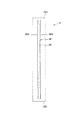
図1〜図4には本発明に係わる鋼管圧入補助装置及びそれを使用した鋼管圧入工法の一実施例が示されている。なお、この実施例では杭圧入機としての公知の油圧式杭圧入機1を使用して鋼管としての鋼管矢板2を地盤3に圧入する場合を例にして説明する。
図1及び図3には本発明の鋼管圧入補助装置10が油圧式杭圧入機1の後方に配設されたクレーン車4のクレーン4Aのフック4Bに吊り下げられた状態で示されている。なお、前記クレーン車4のクレーン4Aには前記フック4Bの他に前記鋼管矢板2を吊り下げる鋼管矢板用ワイヤー4Cが設けられている。
図4に示されるように、鋼管圧入補助装置10の構成部材である円筒形状のケーシング12の外径寸法は油圧式杭圧入機1で地盤3に圧入される鋼管矢板2の内径寸法より小径に形成されている。従って、前記ケーシング12は鋼管矢板2の上部2Aから挿入できるようになっている。なお、図1及び図4に示す前記ケーシング12は縦断面図で示されている。
図1及び図4に示されるように、前記鋼管圧入補助装置10のケーシング12の上端面12Aには鋼管圧入補助装置10の構成部材であるアースオーガ14のモータ16が載置された状態で固定されている。このアースオーガ14は公知のアースオーガでありモータ16の下部にはジョイント部材17を介して長尺状のオーガスクリュー18が着脱可能に取り付けられている。
図1に示されるように、前記アースオーガ14のオーガスクリュー18は前記ケーシング12を挿通すると共にオーガスクリュー18の先端部18Aは前記ケーシング12の下端面12Bより突出するように配設されている。従って、前記アースオーガ14のモータ16を始動させると前記オーガスクリュー18が回転して地盤3を掘削できるようになっている。
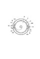
図1及び図3に示されるように、前記ケーシング12の外周面には上下方向に沿ってケーシング12と略同じ長さの第1係止体としての係止凹体20が180°の間隔をおいて2個固定されている。この係止凹体20はレール20A,20Aをケーシング12の外周面に縦方向に向って並行に固定することにより構成されている。
図2及び図3に示されるように、前記係止凹体20のレール20Aとレール20Aの間には係止体収容部22が形成されている。
図2及び図4に示されるように、前記鋼管矢板2の上部2Aの内周面には第2係止体としての係止凸体24が互いに対向して溶接等の適宜手段で2個突設されている。これら係止凸体24は前記ケーシング12の外周面に形成された前記係止凹体20の係止体収容部22にそれぞれ収容されるようになっている。また、前記鋼管矢板2の外周面には継手2B,2Bが溶接等の適宜手段で固定され、鋼管矢板2を連続状態に連結できるようになっている。従って、前記鋼管矢板2は上部2Aの内周面に係止凸体24を設けた点だけが公知の鋼管矢板と相違するだけであり、他の構成は公知の鋼管矢板と同じ構造である。
図1及び図4に示されるように、前記アースオーガ14には吊下用ワイヤー28が取り付けられている。この吊下用ワイヤー28は前記鋼管圧入補助装置10を吊り下げるクレーン車4のクレーン4Aのフック4Bに係止されるようになっている。
1 to 4 show an embodiment of a steel pipe press-fitting auxiliary device and a steel pipe press-fitting method using the same according to the present invention. In this embodiment, a case where a steel
1 and 3 show a steel pipe press-fitting
As shown in FIG. 4, the outer diameter dimension of the
As shown in FIGS. 1 and 4, the
As shown in FIG. 1, the
As shown in FIGS. 1 and 3, a locking recess 20 as a first locking body having a length substantially the same as that of the
As shown in FIGS. 2 and 3, a locking
As shown in FIG. 2 and FIG. 4, a
As shown in FIGS. 1 and 4, a
次に、前記鋼管圧入補助装置10を使用して行われる鋼管圧入工法の一実施例について説明する。
準備段階として前記鋼管矢板2を埋設する基礎工事現場に油圧式杭圧入機1を配設する。また、前記鋼管矢板2を吊り下げて油圧式杭圧入機1に提供すると共に鋼管圧入補助装置10を吊り下げるクレーン車4を配設する。なお、前記鋼管矢板2の上部2A(圧入される場合に上方に位置する方)の内周面には予め前記係止凸体24が互いに対向した状態で2個突設固定されている。
最初に、前記クレーン車4は用意されている前記鋼管矢板2をクレーン4Aに設けられた鋼管矢板用ワイヤー4Cで吊り上げてから前記油圧式杭圧入機1に提供する。図4に示されるように、この鋼管矢板2を提供された油圧式杭圧入機1は鋼管矢板2の上部2Aが上方になるように鋼管矢板2を垂直に立てた状態でチャック部1Aで強固に挟持する。
次に、前記クレーン車4はクレーン4Aのフック4Bを鋼管圧入補助装置10の吊下用ワイヤー28に係止して前記鋼管圧入補助装置10を垂直状に吊り上げてから、鋼管圧入補助装置10のケーシング12を前記油圧式杭圧入機1が挟持している前記鋼管矢板2の上部2Aから挿入する。この時、前記ケーシング12に突設されている係止凹体20の係止体収容部22と鋼管矢板2の上部2Aの内周面に突設されている係止凸体24が対応するように位置決めを行い、ケーシング12の係止体収容部22に鋼管矢板2の係止凸体24が収容されるようにケーシング12を吊り降ろす。
従って、図2に示されるように、前記ケーシング12に固定された係止凹体20の係止体収容部22に鋼管矢板2の係止凸体24が収容された状態になる。
そして、前記鋼管圧入補助装置10をさらに降下させて前記アースオーガ14のモータ16を始動させてオーガスクリュー18を回転させる。これによりケーシング12の下端面12Bよりも下に突出したオーガスクリュー18の先端部18Aが地盤3を掘削し始める。
前記オーガスクリュー18が掘削を開始して地盤3の固さ条件等によってオーガスクリュー18に大きな摩擦抵抗が生じる場合がある。この時、大きな摩擦抵抗がオーガスクリュー18を介してアースオーガ14のモータ16に伝わりモータ16自体が回ろうとしても図2に示されるようにモータ16が固定されているケーシング12の係止凹体20の係止体収容部22には油圧式杭圧入機1のチャック部1Aに強固に挟持されている鋼管矢板2の内周面に突設された係止凸体24が収容されている。このため、前記モータ16自体、ケーシング12自体が回ろうとしても前記係止凸体24によって阻止される。
従って、地盤3の掘削時に前記オーガスクリュー18に大きな摩擦抵抗が作用してもモータ16が固定されているケーシング12は油圧式杭圧入機1のチャック部1Aに強固に挟持されている鋼管矢板2によって回ることを阻止される。
このため、前記アースオーガ14のモータ16自体が回ることが無いので、モータ16の駆動力がスムーズにオーガスクリュー18に伝わり、地盤3が固くてもオーガスクリュー18は円滑に掘削を行うことができる。
この結果、油圧式杭圧入機1で鋼管矢板2を圧入する場合に先に鋼管圧入補助装置10のオーガスクリュー18によって固い地盤3は掘削されるため、前記油圧式杭圧入機1で前記鋼管矢板2を地盤3に円滑に圧入することができる。
また、オーガスクリュー18が地盤3を掘削する場合、前記鋼管圧入補助装置10のケーシング12は油圧式杭圧入機1に強固に挟持されている鋼管矢板2の係止凸体24にガイドされながら下降する状態になるので、従来工法に比べてオーガスクリュー18は高精度で地盤3を掘削することができ、これによりオーガスクリュー18による掘削精度を高めることができる。
Next, an embodiment of a steel pipe press fitting method performed using the steel pipe press fitting
As a preparatory stage, the hydraulic pile press-in machine 1 is disposed at the foundation construction site where the steel
First, the crane 4 lifts the prepared steel
Next, the crane 4 locks the hook 4 </ b> B of the crane 4 </ b> A to the
Therefore, as shown in FIG. 2, the locking
Then, the steel pipe press-fitting
When the
Therefore, even when a large frictional resistance acts on the
For this reason, since the
As a result, when the steel
Further, when the
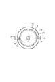
なお、実施例では第1係止体として係止凹体20を示し、第2係止体として係止凸体24を示したが、第1係止体と第2係止体は第1係止体と第2係止体が協働することにより掘削時に鋼管圧入補助装置10のモータ16自体が回ってしまうことを阻止できる構造であれば前記係止凹体20と前記係止凸体24の構成に限定されるものでないことは勿論である。
従って、例えば図5に示されるように、前記係止凹体20を小型に形成したり、あるいは図6に示されるように前記ケーシング12の外周面にレール20Aを1本ずつ設け、鋼管矢板2の係止凸体24と係止させるような構成にしてもよいことは勿論である。
In the embodiment, the locking
Therefore, for example, as shown in FIG. 5, the locking
なお、実施例では地盤3に圧入する鋼管として鋼管矢板2を例にして示したが、圧入する鋼管は鋼管であれば鋼管矢板2に限定されるものでないことは勿論である。
また、実施例では鋼管を圧入する杭圧入機として油圧式杭圧入機1を例にして示したが、鋼管を圧入する杭圧入機であれば油圧式杭圧入機1に限定されるものでないことは勿論である。
なお、実施例ではケーシング12に係止凹体20を2個設け、鋼管矢板2に係止凸体24を2個設けた例を示したが、ケーシング12及び鋼管矢板2に固定する前記係止凹体20及び係止凸体24は1個でも、3個以上でもよいことは勿論である。
In addition, in the Example, although the steel
Moreover, in the Example, although the hydraulic pile presser 1 was shown as an example as a pile presser which presses in a steel pipe, if it is a pile presser which presses in a steel pipe, it is not limited to the hydraulic pile presser 1 Of course.
In addition, in the Example, although the two latching recessed
1 油圧式圧入機
2 鋼管矢板
10 鋼管圧入補助装置
12 ケーシング
14 アースオーガ
16 モータ
18 オーガスクリュー
20 係止凹体
22 係止体収容部
24 係止凸体
DESCRIPTION OF SYMBOLS 1 Hydraulic press-
Claims (4)
A steel pipe press-in method using the steel pipe press-in auxiliary device according to claim 1 or 2 when a steel pipe sheet pile is press-fitted into the ground or rock by a hydraulic pile press-in machine, After the steel pipe sheet pile to be press-fitted into the machine is clamped, the steel pipe press-fitting auxiliary device is suspended by a crane and the first locking body formed on the outer peripheral surface of the casing of the steel pipe press-fitting auxiliary device is held by the hydraulic pile presser The casing is inserted into the steel pipe sheet pile so as to correspond to the second locking body formed on the inner peripheral surface of the steel pipe sheet pile, the earth auger of the steel pipe press-fitting auxiliary device is started, and the ground and bedrock are moved with the auger screw. A steel pipe press-fitting method using a steel pipe press-fitting auxiliary device, wherein the steel pipe sheet pile is press-fitted by excavating and press-fitting the steel pipe sheet pile into the ground or rock by the hydraulic pile press-fitting machine.
Priority Applications (1)
| Application Number | Priority Date | Filing Date | Title |
|---|---|---|---|
| JP2006110627A JP2007284902A (en) | 2006-04-13 | 2006-04-13 | Steel pipe press-fit assisting device and steel pipe press-fitting method using the same |
Applications Claiming Priority (1)
| Application Number | Priority Date | Filing Date | Title |
|---|---|---|---|
| JP2006110627A JP2007284902A (en) | 2006-04-13 | 2006-04-13 | Steel pipe press-fit assisting device and steel pipe press-fitting method using the same |
Publications (1)
| Publication Number | Publication Date |
|---|---|
| JP2007284902A true JP2007284902A (en) | 2007-11-01 |
Family
ID=38756942
Family Applications (1)
| Application Number | Title | Priority Date | Filing Date |
|---|---|---|---|
| JP2006110627A Pending JP2007284902A (en) | 2006-04-13 | 2006-04-13 | Steel pipe press-fit assisting device and steel pipe press-fitting method using the same |
Country Status (1)
| Country | Link |
|---|---|
| JP (1) | JP2007284902A (en) |
Cited By (1)
| Publication number | Priority date | Publication date | Assignee | Title |
|---|---|---|---|---|
| JP2009084822A (en) * | 2007-09-28 | 2009-04-23 | Shinei Kk | Steel pipe press-in auxiliary device and steel pipe press-in method using the same |
Citations (3)
| Publication number | Priority date | Publication date | Assignee | Title |
|---|---|---|---|---|
| JPS54105805A (en) * | 1978-02-07 | 1979-08-20 | Shimizu Construction Co Ltd | Method of noiseless and vibrationless presssin construction of steel pipe pile and steel pipe sheet pile and its device |
| JP2005023707A (en) * | 2003-07-04 | 2005-01-27 | Tosa Kikai Kogyo Kk | Steel pipe pile press-fitting and drawing out machine |
| JP2005256357A (en) * | 2004-03-10 | 2005-09-22 | Jfe Steel Kk | Ready-made pile construction method and holding leader |
-
2006
- 2006-04-13 JP JP2006110627A patent/JP2007284902A/en active Pending
Patent Citations (3)
| Publication number | Priority date | Publication date | Assignee | Title |
|---|---|---|---|---|
| JPS54105805A (en) * | 1978-02-07 | 1979-08-20 | Shimizu Construction Co Ltd | Method of noiseless and vibrationless presssin construction of steel pipe pile and steel pipe sheet pile and its device |
| JP2005023707A (en) * | 2003-07-04 | 2005-01-27 | Tosa Kikai Kogyo Kk | Steel pipe pile press-fitting and drawing out machine |
| JP2005256357A (en) * | 2004-03-10 | 2005-09-22 | Jfe Steel Kk | Ready-made pile construction method and holding leader |
Cited By (1)
| Publication number | Priority date | Publication date | Assignee | Title |
|---|---|---|---|---|
| JP2009084822A (en) * | 2007-09-28 | 2009-04-23 | Shinei Kk | Steel pipe press-in auxiliary device and steel pipe press-in method using the same |
Similar Documents
| Publication | Publication Date | Title |
|---|---|---|
| KR101560681B1 (en) | Vibration-free, noise-free, not soil exhaust S.C.P-PILE and that construction methods | |
| JP3733533B2 (en) | Foundation reinforcement method under pressure of existing structures | |
| JP6286097B1 (en) | U-type steel sheet pile press-fitting device | |
| JP2008196128A (en) | Press-in method of steel sheet pile concurrently using auger | |
| JP3834571B2 (en) | Construction method for underground structures | |
| JP2007284902A (en) | Steel pipe press-fit assisting device and steel pipe press-fitting method using the same | |
| JPH0424398A (en) | Construction of underground space with arched member | |
| JP2726241B2 (en) | Pile head treatment method of cast-in-place foundation pile and tool for performing this treatment | |
| JP4113305B2 (en) | Ground obstruction removal method | |
| JP4635725B2 (en) | Pile construction system | |
| JPH09302654A (en) | Construction method and equipment for steel pipe sheet pile | |
| JP3616898B2 (en) | Method for joining underground structures using propulsion device | |
| JP4543070B2 (en) | Steel pipe press-in auxiliary device and steel pipe press-in method using the same | |
| JP2005194798A (en) | Auger driving device, pile press-in device, and pile press-in method using auger | |
| JP6195376B2 (en) | Ruler for placing steel pipe sheet pile, method for placing steel pipe sheet pile, and swivel excavator used for the method for placing steel pipe sheet pile | |
| JP3681746B1 (en) | Iron sheet pile and its insertion method | |
| KR20090080393A (en) | Ground excavation and support method using cutting force of steel plate and rotating wire saw | |
| KR20150124728A (en) | Sheet Pile Construction Apparatus For Perforating and Pile Driver Work | |
| JP2006009468A (en) | Driving method of medium digging type steel pipe sheet pile and steel pipe sheet pile used therefor | |
| KR0123886B1 (en) | Basic construction pile construction method and device | |
| JP5961441B2 (en) | Steel sheet pile burial excavator and steel sheet pile burial method | |
| JP2000017658A (en) | Pitching-of-pile method of ready-made pile and its device | |
| JP2008013999A (en) | Construction method of cast-in-place concrete pile | |
| JP4719041B2 (en) | Pile press-in method and pile press-out machine | |
| JP2897870B2 (en) | Drilling equipment and medium digging method |
Legal Events
| Date | Code | Title | Description |
|---|---|---|---|
| A621 | Written request for application examination |
Effective date: 20081209 Free format text: JAPANESE INTERMEDIATE CODE: A621 |
|
| A977 | Report on retrieval |
Effective date: 20110107 Free format text: JAPANESE INTERMEDIATE CODE: A971007 |
|
| A131 | Notification of reasons for refusal |
Free format text: JAPANESE INTERMEDIATE CODE: A131 Effective date: 20110119 |
|
| A131 | Notification of reasons for refusal |
Effective date: 20111102 Free format text: JAPANESE INTERMEDIATE CODE: A131 |
|
| A02 | Decision of refusal |
Free format text: JAPANESE INTERMEDIATE CODE: A02 Effective date: 20120328 |