JP2007292012A - Exhaust gas recirculation device for internal combustion engine - Google Patents
Exhaust gas recirculation device for internal combustion engine Download PDFInfo
- Publication number
- JP2007292012A JP2007292012A JP2006123167A JP2006123167A JP2007292012A JP 2007292012 A JP2007292012 A JP 2007292012A JP 2006123167 A JP2006123167 A JP 2006123167A JP 2006123167 A JP2006123167 A JP 2006123167A JP 2007292012 A JP2007292012 A JP 2007292012A
- Authority
- JP
- Japan
- Prior art keywords
- water
- internal combustion
- combustion engine
- exhaust gas
- heat exchange
- Prior art date
- Legal status (The legal status is an assumption and is not a legal conclusion. Google has not performed a legal analysis and makes no representation as to the accuracy of the status listed.)
- Pending
Links
Images



Classifications
-
- F—MECHANICAL ENGINEERING; LIGHTING; HEATING; WEAPONS; BLASTING
- F02—COMBUSTION ENGINES; HOT-GAS OR COMBUSTION-PRODUCT ENGINE PLANTS
- F02M—SUPPLYING COMBUSTION ENGINES IN GENERAL WITH COMBUSTIBLE MIXTURES OR CONSTITUENTS THEREOF
- F02M26/00—Engine-pertinent apparatus for adding exhaust gases to combustion-air, main fuel or fuel-air mixture, e.g. by exhaust gas recirculation [EGR] systems
- F02M26/13—Arrangement or layout of EGR passages, e.g. in relation to specific engine parts or for incorporation of accessories
- F02M26/41—Arrangement or layout of EGR passages, e.g. in relation to specific engine parts or for incorporation of accessories characterised by the arrangement of the recirculation passage in relation to the engine, e.g. to cylinder heads, liners, spark plugs or manifolds; characterised by the arrangement of the recirculation passage in relation to specially adapted combustion chambers
-
- F—MECHANICAL ENGINEERING; LIGHTING; HEATING; WEAPONS; BLASTING
- F02—COMBUSTION ENGINES; HOT-GAS OR COMBUSTION-PRODUCT ENGINE PLANTS
- F02M—SUPPLYING COMBUSTION ENGINES IN GENERAL WITH COMBUSTIBLE MIXTURES OR CONSTITUENTS THEREOF
- F02M26/00—Engine-pertinent apparatus for adding exhaust gases to combustion-air, main fuel or fuel-air mixture, e.g. by exhaust gas recirculation [EGR] systems
- F02M26/13—Arrangement or layout of EGR passages, e.g. in relation to specific engine parts or for incorporation of accessories
- F02M26/22—Arrangement or layout of EGR passages, e.g. in relation to specific engine parts or for incorporation of accessories with coolers in the recirculation passage
- F02M26/29—Constructional details of the coolers, e.g. pipes, plates, ribs, insulation or materials
- F02M26/30—Connections of coolers to other devices, e.g. to valves, heaters, compressors or filters; Coolers characterised by their location on the engine
-
- F—MECHANICAL ENGINEERING; LIGHTING; HEATING; WEAPONS; BLASTING
- F02—COMBUSTION ENGINES; HOT-GAS OR COMBUSTION-PRODUCT ENGINE PLANTS
- F02M—SUPPLYING COMBUSTION ENGINES IN GENERAL WITH COMBUSTIBLE MIXTURES OR CONSTITUENTS THEREOF
- F02M26/00—Engine-pertinent apparatus for adding exhaust gases to combustion-air, main fuel or fuel-air mixture, e.g. by exhaust gas recirculation [EGR] systems
- F02M26/13—Arrangement or layout of EGR passages, e.g. in relation to specific engine parts or for incorporation of accessories
- F02M26/22—Arrangement or layout of EGR passages, e.g. in relation to specific engine parts or for incorporation of accessories with coolers in the recirculation passage
- F02M26/29—Constructional details of the coolers, e.g. pipes, plates, ribs, insulation or materials
- F02M26/32—Liquid-cooled heat exchangers
Landscapes
- Engineering & Computer Science (AREA)
- Chemical & Material Sciences (AREA)
- Combustion & Propulsion (AREA)
- Mechanical Engineering (AREA)
- General Engineering & Computer Science (AREA)
- Exhaust-Gas Circulating Devices (AREA)
Abstract
【課題】V型内燃機関の排気の一部を排気系から吸気系に還流させる際に、その還流排気を冷却するための熱交換装置の搭載性を高めるとともに、その熱交換効率を高めた、V型内燃機関の排気還流装置を提供する。
【解決手段】還流排気を冷却するためのEGRクーラー1を有し、EGRクーラー1は、円筒ハウジング部2と、左右バンク(6L,6R)のシリンダヘッドに円筒ハウジング部2を固定するフランジ部(4L,4R)と、フランジ部を通してシリンダヘッドから直接排気およびウォータジャケット内の水を流入させ、流入させた排気と水との間で熱交換を行う熱交換機構(円筒ハウジング部2内に収容される)とを含む。
【選択図】図2When a part of the exhaust of a V-type internal combustion engine is recirculated from an exhaust system to an intake system, the heat exchange device for cooling the recirculated exhaust is improved and the heat exchange efficiency is improved. An exhaust gas recirculation device for a V-type internal combustion engine is provided.
An EGR cooler (1) for cooling recirculated exhaust gas is provided. The EGR cooler (1) has a cylindrical housing part (2) and a flange part for fixing the cylindrical housing part (2) to the cylinder heads of the left and right banks (6L, 6R). 4L, 4R) and a heat exchange mechanism (accommodated in the cylindrical housing portion 2) that exchanges heat between the exhaust gas and water that has flowed in directly from the cylinder head through the flange portion and the cylinder head. Including).
[Selection] Figure 2
Description
本発明は、内燃機関の排気の一部を排気系から吸気系に還流させる排気還流(EGR;Exhaust Gas Recirculation)技術に係り、特に、排気還流装置を備えたV型内燃機関において、還流排気を効率良く冷却してNOxの発生を低減させるための排気冷却技術に関する。 The present invention relates to an exhaust gas recirculation (EGR) technique for recirculating a part of exhaust gas of an internal combustion engine from an exhaust system to an intake system, and in particular, in a V-type internal combustion engine equipped with an exhaust gas recirculation device, The present invention relates to an exhaust cooling technique for efficiently cooling and reducing the generation of NOx.
内燃機関の排気還流装置としてのEGR装置は、内燃機関の排気系から排出される排ガスの一部を、排気側と吸気側との間の圧力差を利用し排ガス再循環路を介して内燃機関の吸気系に戻し、吸気系に戻された排ガス(還流排気)により内燃機関内での燃料の燃焼を抑制させて燃焼温度を下げ、NOxの発生を低減する。その際、還流排気の温度が高い場合には、吸気系の温度が上昇するため、吸気系で吸入される吸気重量が減少し、特に高負荷時において出力が低下する。また、吸気系に戻す還流排気の量を制御するEGRバルブに高温の還流排気が流通すると、バルブ摺動部分の磨耗やスティックが発生する。
したがって、内燃機関の排気還流装置には、たとえば下記特許文献1に開示されるように、還流排気を冷却するための熱交換装置(EGRクーラー)が搭載される。
An EGR device as an exhaust gas recirculation device for an internal combustion engine uses a part of exhaust gas discharged from an exhaust system of the internal combustion engine through an exhaust gas recirculation path using a pressure difference between an exhaust side and an intake side. The exhaust gas returned to the intake system (recirculated exhaust gas) suppresses the combustion of fuel in the internal combustion engine to lower the combustion temperature and reduce the generation of NOx. At this time, when the temperature of the recirculated exhaust gas is high, the temperature of the intake system rises, so that the weight of intake air sucked in the intake system decreases, and the output decreases particularly at a high load. Further, when high-temperature recirculation exhaust flows through the EGR valve that controls the amount of recirculation exhaust returned to the intake system, wear of the valve sliding portion and sticking occur.
Therefore, the exhaust gas recirculation device of the internal combustion engine is equipped with a heat exchange device (EGR cooler) for cooling the recirculated exhaust gas as disclosed in, for example, Patent Document 1 below.
ところで、EGRクーラーを有する従来の排気還流装置を、V型6気筒やV型8気筒などのV型内燃機関に搭載しようとした場合、搭載性に問題が生ずる場合がある。これは、各気筒が左右バンクに配列されたV型内燃機関の側面には、スタータモータ、オルタネータなどの補機類、クーラーコンプレッサ、オイルフィルタ、エンジンマウントなどの部品が搭載されるため、EGRクーラーの搭載位置を設けることは容易ではないためである。たとえば、上記特許文献1に開示されたような従来のEGRクーラーは、当該文献の図1および図2から明らかなように、機関側面のシリンダブロックに配設されるが、実際には他の部品と干渉して搭載が困難である。 By the way, when trying to mount a conventional exhaust gas recirculation device having an EGR cooler on a V-type internal combustion engine such as a V-type 6 cylinder or a V-type 8 cylinder, there may be a problem in mountability. This is because the EGR cooler is equipped with auxiliary machinery such as a starter motor and alternator, cooler compressor, oil filter, engine mount and other parts on the side of the V-type internal combustion engine in which each cylinder is arranged in left and right banks. This is because it is not easy to provide the mounting position. For example, a conventional EGR cooler as disclosed in Patent Document 1 is disposed in a cylinder block on the engine side as is apparent from FIGS. 1 and 2 of the document. It is difficult to mount due to interference.
また、上記特許文献1に開示されたような従来のEGRクーラーは、当該文献の図2から明らかなように、実質的にはシリンダブロック内のウォータジャケット近辺に排気の還流路を設けることで熱交換を行っているが、この還流路の付近では水の移動が少なく、熱交換の効率が低い。 Further, as is apparent from FIG. 2 of the document, the conventional EGR cooler disclosed in the above-mentioned Patent Document 1 is substantially heated by providing an exhaust gas recirculation path in the vicinity of the water jacket in the cylinder block. Although the exchange is performed, there is little movement of water in the vicinity of the reflux path, and the efficiency of heat exchange is low.
したがって、本発明の目的は、V型内燃機関の排気の一部を排気系から吸気系に還流させる際に、その還流排気を冷却するための熱交換装置の搭載性を高めるとともに、その熱交換効率を高めた、V型内燃機関の排気還流装置を提供することにある。 Accordingly, an object of the present invention is to improve the mountability of a heat exchange device for cooling the recirculated exhaust gas when recirculating a part of the exhaust gas of the V-type internal combustion engine from the exhaust system to the intake system, and to perform the heat exchange. An object of the present invention is to provide an exhaust gas recirculation device for a V-type internal combustion engine with improved efficiency.
上記目的を達成するために、本発明は、各気筒が左右バンクに配列されたV型内燃機関の排気の一部を排気系から吸気系に還流させる排気還流装置であって、還流排気を冷却するための熱交換装置を有し、その熱交換装置は、第1筐体と、左右一対の固定部と、左右一対の第1流入口と、左右一対の第2流入口と、熱交換機構と、第1流出口と、第2流出口とを備えている。 In order to achieve the above object, the present invention provides an exhaust gas recirculation device for recirculating a part of exhaust gas of a V-type internal combustion engine in which each cylinder is arranged in left and right banks from an exhaust system to an intake system, and cooling the recirculated exhaust gas The heat exchange device includes a first housing, a pair of left and right fixing portions, a pair of left and right first inflow ports, a pair of left and right second inflow ports, and a heat exchange mechanism. And a first outlet and a second outlet.
固定部は、第1筐体の左右端に設けられ、左右バンクのシリンダヘッドに第1筐体を固定する。これにより、V型内燃機関の左右バンクにおける左右方向の剛性が向上するため、機関騒音が低減する。 The fixing portion is provided at the left and right ends of the first casing, and fixes the first casing to the cylinder heads of the left and right banks. As a result, the left-right rigidity in the left and right banks of the V-type internal combustion engine is improved, and engine noise is reduced.
一方、第1流入口は、左右バンクのシリンダヘッドに連結され、各バンクの排気ポートからの排気が流入する。第2流入口は、左右バンクのシリンダヘッドに連結され、各バンク内に設けられたウォータジャケットから水が流入する。熱交換機構は、第1筐体に収容され、第1流入口から流入する排気と、第2流入口から流入する水との間で熱交換を行う。第1流出口は、熱交換機構によって冷却された排気が、内燃機関の吸気系に向けて流出する。第2流出口は、熱交換機構において熱交換を受けた水が、内燃機関に取り付けられたウォータポンプに向けて流出する。 On the other hand, the first inlet is connected to the cylinder heads of the left and right banks, and the exhaust from the exhaust ports of each bank flows in. The second inlet is connected to the cylinder heads of the left and right banks, and water flows from a water jacket provided in each bank. The heat exchange mechanism is accommodated in the first housing and performs heat exchange between the exhaust gas flowing in from the first inlet and the water flowing in from the second inlet. At the first outlet, the exhaust cooled by the heat exchange mechanism flows out toward the intake system of the internal combustion engine. At the second outlet, water that has undergone heat exchange in the heat exchange mechanism flows out toward a water pump attached to the internal combustion engine.
本発明に係る排気還流装置の熱交換装置は、第1流入口および第2流入口がシリンダヘッドに連結しているため、各バンクのシリンダヘッドから排気および水を導入するための管を必要とせず、車両における機関室内の搭載性が高い。 In the heat exchange device of the exhaust gas recirculation apparatus according to the present invention, since the first inlet and the second inlet are connected to the cylinder head, a pipe for introducing exhaust and water from the cylinder head of each bank is required. In addition, the vehicle is highly mountable in the engine room.
本発明に係る排気還流装置の熱交換装置では、各バンク内に設けられたウォータジャケットから第2流入口から水が導入され、その導入された水が熱交換機構によって熱交換を受け、その後に第2流出口からウォータポンプに向けて流出する。すなわち、常に熱交換用の水が循環しているため、熱交換効率が高い。したがって、排気を効率良く冷却して内燃機関の吸気系に戻すことができる。 In the heat exchange device of the exhaust gas recirculation apparatus according to the present invention, water is introduced from the second inlet from the water jacket provided in each bank, and the introduced water is subjected to heat exchange by the heat exchange mechanism, and thereafter It flows out from the second outlet toward the water pump. That is, heat exchange efficiency is high because water for heat exchange is constantly circulating. Therefore, the exhaust can be efficiently cooled and returned to the intake system of the internal combustion engine.
本発明によれば、V型内燃機関の排気の一部を排気系から吸気系に還流させる際に、その還流排気を冷却するための熱交換装置の搭載性を高めることができるとともに、その熱交換効率を高めることができる。 According to the present invention, when a part of the exhaust gas of the V-type internal combustion engine is recirculated from the exhaust system to the intake system, it is possible to improve the mountability of the heat exchange device for cooling the recirculated exhaust gas and Exchange efficiency can be improved.
以下、本発明に係るV型内燃機関の排気還流装置の実施の形態について図を参照して説明する。ここで、V型内燃機関としてはガソリン機関またはディーゼル機関のいずれでも構わない。
なお、以下の実施形態の説明では、機関が車両に搭載された場合の気筒の配列方向を基準として左右前後の方向を規定するものとする。
Embodiments of an exhaust gas recirculation device for a V-type internal combustion engine according to the present invention will be described below with reference to the drawings. Here, the V-type internal combustion engine may be either a gasoline engine or a diesel engine.
In the following description of the embodiments, the left and right and front and rear directions are defined based on the cylinder arrangement direction when the engine is mounted on a vehicle.
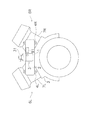
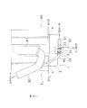
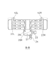
図1は、本発明の一実施形態に係る排気還流装置を含むV型内燃機関の背面図である。図2は、本発明の一実施形態に係る排気還流装置を含むV型内燃機関の平面図である。
図1および図2に示すように、V型内燃機関では、各気筒が左右バンク(左バンク6L,右バンク6R)に配列されて収容されている。左バンク6Lは、左シリンダヘッド7Lを含み、右バンク6Rは、右シリンダヘッド7Rを含む。左右のシリンダヘッドの下部には、シリンダブロック3が設けられる。
FIG. 1 is a rear view of a V-type internal combustion engine including an exhaust gas recirculation apparatus according to an embodiment of the present invention. FIG. 2 is a plan view of a V-type internal combustion engine including an exhaust gas recirculation apparatus according to an embodiment of the present invention.
As shown in FIGS. 1 and 2, in the V-type internal combustion engine, the cylinders are arranged and accommodated in left and right banks (
(排気還流装置の構成)
以下、図1および図2を参照して、本実施形態に係る排気還流装置の構成を説明する。
実施形態に係る排気還流装置は、EGRバルブを一体化したEGRクーラー1(熱交換装置)を有している。
図1および図2に示すように、EGRクーラー1は、主要部として略円筒状の筐体(第1筐体)として円筒ハウジング部2を含み、この円筒ハウジング部2の左右端に設けられる左右一対のフランジ部4L,4Rによって、円筒ハウジング部2が左右バンク間に固定される。すなわち、図2において、左フランジ部4Lは、P1L面において左バンク6Lの左シリンダヘッド7Lに取り付けられ、右フランジ部4Rは、P1R面において右バンク6Rの右シリンダヘッド7Rに取り付けられる。P1L面とP1R面は必ずしも同一平面である必要はない。
(Configuration of exhaust gas recirculation device)
Hereinafter, the configuration of the exhaust gas recirculation apparatus according to the present embodiment will be described with reference to FIGS. 1 and 2.
The exhaust gas recirculation device according to the embodiment has an EGR cooler 1 (heat exchange device) integrated with an EGR valve.
As shown in FIGS. 1 and 2, the EGR cooler 1 includes a
このEGRクーラー1では、後述するように、左右のフランジ部4L,4Rにそれぞれ水路およびガス路が形成されており、左右のシリンダヘッド7L,7Rから、ウォータジャケット内の水と、排気ポートから排出される排気とを導入することができるようになっている。すなわち、図示しないが、各バンクのシリンダヘッド7L,7Rには、左右のフランジ部4L,4Rの水路およびガス路に対応する位置に、ウォータジャケット内の水および排気ポートから排出される排気を導入する通路が加工されている。
In the EGR cooler 1, as will be described later, water passages and gas passages are formed in the left and
EGRクーラー1では、各バンクからそれぞれ導入された水と排気との熱交換を行う。この熱交換によって冷却された排気のうち、EGRバルブ31の動作によって定まる一部の量の排気(還流排気)が、図2に示すように、EGRクーラー1に設けられた排気還流ポート32から流出し、この排気還流ポート32に接続されたEGRチューブ90を通って吸気パイプ80(吸気系)に戻される。そして、エアクリーナからの新気と還流排気とが混合された吸気は、吸気コレクタ81に導入され、燃焼のために各気筒に送られる。
なお、図1では、排気還流ポート32、EGRチューブ90、吸気パイプ80、吸気コレクタ81を図示していない。
In the EGR cooler 1, heat exchange is performed between water and exhaust introduced from each bank. Among the exhaust cooled by this heat exchange, a part of the exhaust (recirculation exhaust) determined by the operation of the
In FIG. 1, the exhaust
一方、熱交換によって高温となった水の一部は、図2に示すように、EGRクーラー1に設けられた第1流出ポート33と、その第1流出ポート33に接続されたチューブ91とを介して、ラジエータ、さらにはウォータポンプに戻される。これによって、機関冷却システム内に、本実施形態に係る排気還流装置のEGRクーラー1が組み込まれる。
On the other hand, as shown in FIG. 2, some of the water that has become hot due to heat exchange has a
また、熱交換によって高温となった水の他の一部は、図2に示すように、EGRクーラー1に設けられた第2流出ポート34と、その第2流出ポート34に接続されたチューブ92とを介して、車室内空調装置の熱交換器(ヒータコア)に向かう。
なお、熱交換によって高温となった水の一部を車室内空調装置の熱交換器に向ける構成は、還流排気の冷却のためには必ずしも必要ないが、一般に熱損失の少ないディーゼル機関ではヒータ効率が良くないため、ディーゼル機関ではかかる構成が好ましい。
Further, as shown in FIG. 2, the other part of the water that has become hot due to the heat exchange includes a
Note that the configuration in which a part of the water that has become hot due to heat exchange is directed to the heat exchanger of the vehicle interior air conditioner is not always necessary for cooling the recirculated exhaust gas. Therefore, such a configuration is preferable for a diesel engine.
(EGRクーラー1の構成)
次に、実施形態に係る排気還流装置に搭載されたEGRクーラー1の構成を、図3〜8を参照して説明する。
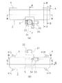
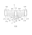
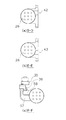
図3において、(a)はEGRクーラー1の平面図、(b)はEGRクーラー1の背面図(内燃機関の背面側から見た図)である。図4は、EGRクーラー1の側面図(図3(a)の矢視G)である。図5は、図3(a)におけるA−A断面図である。図6は、図3(b)におけるB−B断面図である。図7は、図3(b)におけるC−C断面図である。図8において、(a)は図3(a)におけるD−D断面図、(b)は図3(a)におけるE−E断面図、(c)は図3(a)におけるF−F断面図である。
(Configuration of EGR cooler 1)
Next, the structure of the EGR cooler 1 mounted on the exhaust gas recirculation apparatus according to the embodiment will be described with reference to FIGS.
3A is a plan view of the EGR cooler 1, and FIG. 3B is a rear view of the EGR cooler 1 (a view seen from the back side of the internal combustion engine). FIG. 4 is a side view of the EGR cooler 1 (indicated by an arrow G in FIG. 3A). FIG. 5 is a cross-sectional view taken along the line AA in FIG. 6 is a cross-sectional view taken along the line BB in FIG. FIG. 7 is a cross-sectional view taken along the line CC in FIG. 8A is a sectional view taken along line DD in FIG. 3A, FIG. 8B is a sectional view taken along line EE in FIG. 3A, and FIG. 8C is a sectional view taken along line FF in FIG. FIG.
先ず図3および図4を参照すると、本実施形態におけるEGRクーラー1は、熱交換機構を収容する円筒ハウジング部2(第1筐体)と、EGRバルブを収容するバルブハウジング部3(第2筐体)と、フランジ部4とを有する。各ハウジング部は、たとえばステンレス材などの排気ガスの耐腐食性を備えた材質で形成されることが望ましい。
3 and 4, the EGR cooler 1 in this embodiment includes a cylindrical housing portion 2 (first housing) that houses a heat exchange mechanism, and a valve housing portion 3 (second housing) that houses an EGR valve. Body) and the
フランジ部4は、円筒ハウジング部2の端部の左右2箇所に配設され、内燃機関のシリンダヘッドに対する取り付け部位となる左取付穴41L(2箇所)および右取付穴41R(2箇所)が設けられる。この左取付穴41Lおよび右取付穴41Rを利用して、EGRクーラー1がV型内燃機関の各バンクに締結(固定)される。すなわち、左取付穴41Lは、左バンクのシリンダヘッドに締結され、右取付穴41Rは右バンクのシリンダヘッドに締結される。左右の取付穴の距離は、Vバンクの形状、バンク角に応じて適宜設定される。
The
バルブハウジング部3に収容されるEGRバルブ31は、機関負荷、機関速度等に応じて、熱交換機構によって冷却された排気のうち、外部のEGRチューブ90(図2参照)に流出する量(吸気系に戻す量)を決定する。
バルブハウジング部3には、還流排気を流出させるための排気還流ポート32が取り付けられ、排気還流ポート32にはEGRチューブ90が接続される。
The
An exhaust
バルブハウジング部3は、熱交換機構において熱交換を受けた水を流出させるための2系統のポート、すなわち、第1流出ポート33および第2流出ポート34が取り付けられている。
第1流出ポート33は、バルブハウジング部3に対して円筒ハウジング部2の長手方向と略平行であって、かつ、水の流出方向が右方向となるように取り付けられている。第1流出ポート33には、EGRクーラー1から排水される水を車両のラジエータ、さらにはウォータポンプに導くためのチューブ91(図2参照)が接続される。
第2流出ポート34は、第1流出ポート33と垂直方向であって、かつ、水の流出方向が車両後方となるように取り付けられる。この第2流出ポート34には、EGRクーラー1から排水される水を車両のルームヒータ(車室内空調装置)のヒータコア(熱交換器)に導くための外部のチューブ92(図2参照)が接続される。
The
The
The
なお、排気還流ポート32、第1流出ポート33および第2流出ポート34の各ポート向きについて、図3に示したポート向きは一例であって、内燃機関が搭載されるエンジンルームのレイアウトに応じて適宜変更させることは可能である。たとえば、各ポートをバルブハウジング部3に対してロー付けする場合、バルブハウジング部3におけるロー付け前のポート部分の加工角度を変更させることで、ポート向きを変更することができる。
Note that the orientation of the
次に、図5〜8を参照して、円筒ハウジング部2、バルブハウジング部3およびフランジ部4の内部構造を説明する。なお、円筒ハウジング部2およびフランジ部4の内部構造は左右対称であるため、重複説明を適宜省略する。
Next, the internal structure of the
先ず、フランジ部4(左フランジ部4L,右フランジ部4R)の内部構造を説明する。
図5には、理解の容易のため、A−A断面図のみではなく、フランジ部4の断面を点線によって表示している。たとえば、左フランジ部4Lには、水路(左側)42Lおよびガス路(左側)43Lとしての円形の開口部が2箇所設けられている。そして、EGRクーラー1がシリンダヘッドに取り付けられる状態で、水路(左側)42Lおよびガス路(左側)43Lが接合するシリンダヘッドの面には、水路(左側)42Lおよびガス路(左側)43Lと対応する位置に、それぞれ水および排気を流出させるための連通路(図示せず)が設けられている。かかるシリンダヘッドにおける連通路は、ウォータジャケットおよび左バンクの排気ポートと連通し、この連通路を通して、水および排気がそれぞれ水路(左側)42Lおよびガス路(左側)43L導かれる。
First, the internal structure of the flange portion 4 (left
In FIG. 5, for easy understanding, not only the AA cross-sectional view but also the cross-section of the
水路(左側)42Lは、円筒ハウジング部2内の水容積室(左側)23Lと連通しており、ガス路(左側)43Lは、円筒ハウジング部2内のガス容積室(左側)21Lと連通している。ここで、円筒ハウジング部2内では、水容積室(左側)23Lとガス容積室(左側)21Lとは、第1仕切り板(左側)51Lによって区画されている。したがって、図5では、水路(左側)42Lがガス路(左側)43Lよりも上方に設けられているものの、これに限られず、水および排気をそれぞれ水容積室(左側)23Lおよびガス容積室(左側)21Lに導入できればよい。すなわち、図5において、水路(左側)42Lおよびガス路(左側)43Lの上下方向の位置は変更可能である。
The water channel (left side) 42L communicates with the water volume chamber (left side) 23L in the
同様に、右フランジ部4Rには、水路(右側)42Rおよびガス路(右側)43Rとしての円形の開口部が2箇所設けられ、それぞれ右バンクのシリンダヘッドから水および排気を導くための流路を形成する。
Similarly, the
ここで、左フランジ部4Lのシリンダヘッド取付面は、同一平面とし、水路(左側)42Lおよびガス路(左側)43Lに対して単一のシール材(ガスケット)をシリンダヘッド取付面に設けることが、コストおよび取付工数の低減の観点から好ましい。右フランジ部4Rについても同様である。
Here, the cylinder head mounting surface of the
次に、円筒ハウジング部2(第1筐体)とバルブハウジング部3(第2筐体)の内部構造を説明する。なお、円筒ハウジング部2の内部構造は、本発明の熱交換機構の一実施形態である。
Next, the internal structure of the cylindrical housing part 2 (first housing) and the valve housing part 3 (second housing) will be described. The internal structure of the
図6および図8に示すように、円筒ハウジング部2は、ガス容積室(左側)21Lおよびガス容積室(右側)21R(一対の第1ガス容積室)、ガス容積室(中央)22(第2ガス容積室)、水容積室(左側)23Lおよび水容積室(右側)23R(一対の第1水容積室)、複数のガス管(左側)26L、および、複数のガス管(右側)26Rを収容する。
ガス容積室(左側)21Lと水容積室(左側)23Lは、第1仕切り板(左側)51Lによって区画される。ガス容積室(右側)21Rと水容積室(右側)23Rは、第1仕切り板(右側)51Rによって区画される。水容積室(左側)23Lとガス容積室(中央)22は、第2仕切り板(左側)52Lによって区画される。水容積室(右側)23Rとガス容積室(中央)22は、第2仕切り板(右側)52Rによって区画される。
6 and 8, the
The gas volume chamber (left side) 21L and the water volume chamber (left side) 23L are partitioned by a first partition plate (left side) 51L. The gas volume chamber (right side) 21R and the water volume chamber (right side) 23R are partitioned by a first partition plate (right side) 51R. The water volume chamber (left side) 23L and the gas volume chamber (center) 22 are partitioned by a second partition plate (left side) 52L. The water volume chamber (right side) 23R and the gas volume chamber (center) 22 are partitioned by a second partition plate (right side) 52R.
ガス容積室(左側)21Lとガス容積室(中央)22との間には、複数のガス管(左側)26Lが並設される。ガス容積室(右側)21Rとガス容積室(中央)22との間には、複数のガス管(右側)26Rが並設される。ガス管(左側)26Lおよびガス管(右側)26Rの両端は開口している。したがって、このガス管(左側)26Lおよびガス管(右側)26Rは、それぞれガス容積室(左側)21Lおよびガス容積室(右側)21R内の排気をガス容積室(中央)22へ導くための流路を形成する。 A plurality of gas pipes (left side) 26L are arranged in parallel between the gas volume chamber (left side) 21L and the gas volume chamber (center) 22. A plurality of gas pipes (right side) 26R are arranged in parallel between the gas volume chamber (right side) 21R and the gas volume chamber (center) 22. Both ends of the gas pipe (left side) 26L and the gas pipe (right side) 26R are open. Accordingly, the gas pipe (left side) 26L and the gas pipe (right side) 26R are flow paths for guiding the exhaust in the gas volume chamber (left side) 21L and the gas volume chamber (right side) 21R to the gas volume chamber (center) 22, respectively. Form a road.
なお、ガス容積室(中央)22とこれに対応した位置に設けられるバルブハウジング部3は、円筒ハウジング部2の略中央、すなわち、EGRクーラー1を内燃機関に搭載した場合に左右バンク間の略中央位置にあることが好ましい。これによって、水容積室(左側)23Lおよび水容積室(右側)23R内の水の通流による冷却効率が左右で均等になるため、左右バンクからの排気を均等に冷却させることができる。また、ガス容積室(中央)22とこれに対応した位置に設けられるバルブハウジング部3を、円筒ハウジング部2の中央に配置することで、円筒ハウジング部2の内部構造を左右対称とすることができるため、部品点数および組み付け工数が低減される。
The gas volume chamber (center) 22 and the
図8には、ガス管26L,26Rの断面形状が図示されている。図8に示すように、本実施形態では、細径のパイプに排気を通流させ、太径の円筒ハウジング部2内に水を通流させている。これは、排気を細径のパイプに通流させることによって、排気(ガス)の流速を高め、円筒ハウジング部2内のガス容積室に煤(スス)を付着させないためである。ガス管26L,26Rの内面や端部に煤が付着したとしても、高速のガス流によって付着した煤を脱落させる効果も期待できる。
FIG. 8 shows the cross-sectional shapes of the
図6において、円筒ハウジング部2の円筒外壁20には、水容積室23(23L,23R)と水容積室57(第2水容積室)とが接する左右2箇所の位置に、左開口部28Lおよび右開口部28R(一対の第2開口部)が設けられる。この左開口部28Lおよび右開口部28Rによって、水容積室(左側)23Lおよび水容積室(右側)23Rを通流する水がそれぞれバルブハウジング部3内の水容積室57に導入される。
図7において、円筒ハウジング部2の円筒外壁20には、ガス容積室(中央)22とガス容積室58(第3ガス容積室)とが接する位置に、中央開口部55(第1開口部)が設けられる。この中央開口部55によって、ガス容積室(中央)22内の排気がバルブハウジング部3内のガス容積室58に導入される。
In FIG. 6, the left outer opening 28 </ b> L is located at two positions on the left and right sides where the water volume chamber 23 (23 </ b> L, 23 </ b> R) and the water volume chamber 57 (second water volume chamber) are in contact with the cylindrical
In FIG. 7, the central opening 55 (first opening) is located at a position where the gas volume chamber (center) 22 and the gas volume chamber 58 (third gas volume chamber) are in contact with the cylindrical
図7に示すように、バルブハウジング部3の内部では、水容積室57とガス容積室58とは、通路壁56で区画されている。そして、左開口部28Lおよび右開口部28Rから水容積室57に導入される水は、第1流出ポート33および第2流出ポート34へ通流する。中央開口部55からガス容積室58に導入される排気は、中央開口部55よりも上方のEGRバルブ31へ向かう。
As shown in FIG. 7, the
図8(c)に示すように、EGRバルブ31(制御弁)は、ステッピングモータ35と、そのステッピングモータ35によって上下方向に動作するシャフト36とを含んで構成される。EGRバルブ31は、外部のECU(Engine Control Unit;図示せず)からの制御指令によってシャフト36の上下方向の動作量が特定され、これによりバルブ開口面積が規定される。かかる構成により、ガス容積室58の排気のうち、バルブ開口面積に応じた量の排気が還流排気として吸気系に戻されることになる。
なお、EGRバルブ31は、ステッピングモータではなく、リニアソレノイドによってシャフト36を駆動するような構成にしてもよい。
As shown in FIG. 8C, the EGR valve 31 (control valve) includes a stepping
The
ここで、図7および図8(c)に示すように、本実施形態におけるEGRクーラー1では、水容積室57がEGRバルブ31に隣接して配置されているため、水容積室57に導入された水がEGRバルブ31のバルブハウジング部3に対する取付位置近辺まで通流する。したがって、EGRバルブ31の冷却が還流排気の冷却と同時に行われる。EGRバルブは、一般に、内部にバルブ冷却用の水路を設けている場合があるが、本実施形態におけるEGRバルブ31は、そのようなバルブ冷却用水路を設ける必要がないので、低コスト化を図ることができる。
Here, as shown in FIG. 7 and FIG. 8C, in the EGR cooler 1 in this embodiment, the
以上、EGRクーラー1の構造について説明してきたが、かかる構造は点付け(溶接)およびロー付けによって用意に製造することができる。この製造方法では、(1)すべての構成部品を予め点付け(溶接)しておき、(2)各部品間の接合部分にロー材を塗布し、(3)ロー材を塗布した状態で電気炉を通す。これによって、電気炉に通した後には、ロー材が溶解し、EGRクーラー1の各構成部品間が完全に接合されることになる。なお、各部品を2段階でロー付けするときには、最初のロー材に溶解温度よりも、後のロー材の溶解温度を高く設定する必要がある。 The structure of the EGR cooler 1 has been described above. However, such a structure can be easily manufactured by spotting (welding) and brazing. In this manufacturing method, (1) all component parts are spotted (welded) in advance, (2) a brazing material is applied to the joint portion between the parts, and (3) the electric material is applied with the brazing material applied. Pass through the furnace. Thus, after passing through the electric furnace, the brazing material is melted, and the components of the EGR cooler 1 are completely joined. When each part is brazed in two stages, it is necessary to set the melting temperature of the subsequent brazing material higher than the melting temperature of the first brazing material.
(EGRクーラー1の動作)
次に、実施形態に係る排気還流装置に搭載されたEGRクーラー1の動作を、図9および図10を参照して説明する。
図9は、図6同様のB−B断面図であるが、水の通流状態を矢印で示してある。図10は、図7同様のC−C断面図であるが、排気の通流状態を矢印で示してある。
(Operation of EGR cooler 1)
Next, the operation of the EGR cooler 1 mounted on the exhaust gas recirculation apparatus according to the embodiment will be described with reference to FIGS. 9 and 10.
FIG. 9 is a cross-sectional view taken along the line B-B similar to FIG. FIG. 10 is a cross-sectional view taken along the line C-C similar to FIG. 7, but the exhaust flow state is indicated by arrows.
機関の運転が開始されると、クランクの回転に連動してウォータポンプが動作を開始し、各バンク内のウォータジャケット内の水が循環し、その水が水路(左側)42Lおよび水路(右側)42Rを通してEGRクーラー1内に導入される。
図9に示すように、EGRクーラー1では、左バンクから水路(左側)42Lに導入された水が水容積室(左側)23Lを通流し、左開口部28Lを介して水容積室57に導入される。右バンクから水路(右側)42Rに導入された水が水容積室(右側)23Rを通流し、右開口部28Rを介して水容積室57に導入される。左右から流れ込んだ水は、水容積室57で合流し、一部は第1流出ポート33から流出し、その他の一部は第2流出ポート34から流出する。
When the operation of the engine is started, the water pump starts operating in conjunction with the rotation of the crank, the water in the water jacket in each bank circulates, and the water is the water channel (left side) 42L and the water channel (right side). It is introduced into the EGR cooler 1 through 42R.
As shown in FIG. 9, in the EGR cooler 1, the water introduced from the left bank into the water channel (left side) 42L flows through the water volume chamber (left side) 23L and is introduced into the
円筒ハウジング部2内の熱交換機構によって高温となった水の一部は、第1流出ポート33と、その第1流出ポート33に接続された外部のチューブ91とを介して、ラジエータ、さらにはウォータポンプに戻される(図2参照)。
円筒ハウジング部2内の熱交換機構によって高温となった水の他の一部は、第2流出ポート34と、その第2流出ポート34に接続された外部のチューブ92とを介して、車室内空調装置の熱交換器(ヒータコア)に向かう(図2参照)。
A part of the water heated to a high temperature by the heat exchange mechanism in the
Other part of the water heated to a high temperature by the heat exchange mechanism in the
一方、機関の運転が開始されると、各気筒が燃焼を開始し、各気筒に連通する排気ポートから排気が排出される。そして、左バンクからの排気はガス路(左側)43Lに導入され、右バンクからの排気はガス路(右側)43Rに導入される。
図10に示すように、EGRクーラー1では、左バンクからガス路(左側)43Lに導入された排気が、ガス容積室(左側)21Lを通過した後、ガス管(左側)26Lを通流し、ガス容積室(中央)22および中央開口部55を介してガス容積室58に導入される。右バンクからガス路(右側)43Rに導入された排気が、ガス容積室(右側)21Rを通過した後、ガス管(右側)26Rを通流し、ガス容積室(中央)22および中央開口部55を介してガス容積室58に導入される。すなわち、左右から流れ込んだ排気は、ガス容積室(中央)22で合流して、中央開口部55を介してガス容積室58へ向かう。
On the other hand, when the operation of the engine is started, each cylinder starts to combust and exhaust is discharged from an exhaust port communicating with each cylinder. The exhaust from the left bank is introduced into the gas path (left side) 43L, and the exhaust from the right bank is introduced into the gas path (right side) 43R.
As shown in FIG. 10, in the EGR cooler 1, the exhaust gas introduced from the left bank into the gas passage (left side) 43L passes through the gas volume chamber (left side) 21L, and then flows through the gas pipe (left side) 26L. The gas is introduced into the
ここで、ガス管(左側)26Lおよびガス管(右側)26Rの周囲では、上述したように、それぞれ水容積室(左側)23Lおよび水容積室(右側)23R内の水が通流しているために、その水と管内の排気ガスとの間で効率良く熱交換が行われる。また、排気ガスがガス容積室58に導入された後も、ガス容積室58の周囲は水容積室57で覆われているため、熱交換が行われる。すなわち、EGRクーラー1に導入された排気ガスは十分に冷却された状態で、EGRバルブ31を通過する。このようにして、十分に冷却された還流排気が吸気系に戻されることになる。
Here, as described above, water in the water volume chamber (left side) 23L and the water volume chamber (right side) 23R flows around the gas pipe (left side) 26L and the gas pipe (right side) 26R, respectively. In addition, heat exchange is efficiently performed between the water and the exhaust gas in the pipe. Further, even after the exhaust gas is introduced into the
<本排気還流装置の特徴>
(1)
以上説明したように、この排気還流装置は、V型内燃機関に取り付けられ、還流排気を冷却するためのEGRクーラー1(熱交換装置)を有し、EGRクーラー1は、円筒ハウジング部2(第1筐体)と、円筒ハウジング部2の左右端に設けられ、左右バンクのシリンダヘッドに円筒ハウジング部2を固定する左右一対のフランジ部4(固定部)と、左右バンクのシリンダヘッドに連結され、各バンクの排気ポートからの排気が流入する左右一対のガス路43(第1流入口)と、左右バンクのシリンダヘッドに連結され、各バンク内に設けられたウォータジャケットから水が流入する左右一対の水路42(第2流入口)と、円筒ハウジング部2に収容され、ガス路43(第1流入口)から流入する排気と、水路42(第2流入口)から流入する水との間で熱交換を行う熱交換機構と、熱交換機構によって冷却された排気が、内燃機関の吸気系に向けて流出する排気還流ポート32(第1流出口)と、熱交換機構において熱交換を受けた水が、内燃機関に取り付けられたウォータポンプに向けて流出する第1流出ポート33(第2流出口)と、を有する。
<Characteristics of the exhaust gas recirculation device>
(1)
As described above, this exhaust gas recirculation device is attached to a V-type internal combustion engine and has an EGR cooler 1 (heat exchange device) for cooling the recirculated exhaust gas. 1 housing), a pair of left and right flange portions 4 (fixing portions) which are provided at the left and right ends of the
すなわち、本排気還流装置のEGRクーラー1は、ガス路43(第1流入口)および水路42(第2流入口)がシリンダヘッドに連結しているため、各バンクのシリンダヘッドから排気および水を導入するための管を必要とせず、車両における機関室内の搭載性が高い。 That is, the EGR cooler 1 of the present exhaust gas recirculation apparatus has the gas passage 43 (first inlet) and the water passage 42 (second inlet) connected to the cylinder head. There is no need for a pipe for introduction, and the vehicle is highly mountable in the engine room.
また本排気還流装置のEGRクーラー1では、各バンク内に設けられたウォータジャケットから第1流出ポート33(第2流入口)から水が導入され、その導入された水が円筒ハウジング部2内の熱交換機構によって熱交換を受け、その後に第1流出ポート33(第2流出口)から外部のウォータポンプに向けて流出する。すなわち、常に熱交換用の水が循環しているため、熱交換効率が高い。
In the EGR cooler 1 of the present exhaust gas recirculation apparatus, water is introduced from a first outlet port 33 (second inlet) from a water jacket provided in each bank, and the introduced water is stored in the
(2)
この排気還流装置が装備された内燃機関が、車室内空調装置を備えた車両に搭載される場合には、円筒ハウジング部2内の熱交換機構において熱交換を受けた水が、その車室内空調装置の熱交換器(ヒータコア)に向けて流出する第2流出ポート34(第3流出口)をさらに備えることが好ましい。
かかる構成によれば、円筒ハウジング部2内の熱交換機構によって高温となった水がヒータコアに与えられるので、ヒータコアにおける熱交換機能を向上させることができる。
(2)
When the internal combustion engine equipped with this exhaust gas recirculation device is mounted on a vehicle equipped with a vehicle interior air conditioner, the water that has undergone heat exchange in the heat exchange mechanism in the
According to such a configuration, water heated to a high temperature by the heat exchange mechanism in the
(3)
本実施形態に係る排気還流装置のEGRクーラー1では、排気還流ポート32(第1流出口)および第1流出ポート33(第2流出口)は、V型内燃機関の左右バンクの略中央位置に配設されていることが好ましい。
かかる構成によれば、円筒ハウジング部2において、水容積室(左側)23Lおよび水容積室(右側)23R内の水の通流による冷却効率が左右で均等になるため、左右バンクからの排気を均等に冷却させることができる。また、ガス容積室(中央)22とこれに対応するバルブハウジング部3を、EGRクーラー1の中央に配置することで、円筒ハウジング部2の内部構造を左右対称とすることができるため、部品点数および組み付け工数が低減される。
(3)
In the EGR cooler 1 of the exhaust gas recirculation apparatus according to the present embodiment, the exhaust gas recirculation port 32 (first outlet) and the first outlet port 33 (second outlet) are located at substantially central positions of the left and right banks of the V-type internal combustion engine. It is preferable that it is disposed.
According to such a configuration, in the
(4)
本実施形態に係る排気還流装置のEGRクーラー1では、ガス路43(第1流入口)と水路42(第2流入口)とは、同一面によって形成され、その同一面において、単一のシール材によって封止しつつ、シリンダヘッドと接合されることが好ましい。
かかる構成によれば、部品点数および組み付け工数が低減される。
(4)
In the EGR cooler 1 of the exhaust gas recirculation apparatus according to the present embodiment, the gas passage 43 (first inlet) and the water passage 42 (second inlet) are formed by the same surface, and a single seal is formed on the same surface. It is preferable to be joined to the cylinder head while being sealed with a material.
According to such a configuration, the number of parts and the number of assembly steps are reduced.
(5)
本実施形態に係る排気還流装置のEGRクーラー1では、バルブハウジング部3において、EGRバルブ31と隣接する位置に水容積室57(第2水容積室)を設けている。
かかる構成によれば、水容積室57内の水によって、EGRバルブ31の冷却が行われる。したがって、EGRバルブの内部に冷却用水路を設ける必要がなく、EGRバルブの低コスト化を図ることができる。
(5)
In the EGR cooler 1 of the exhaust gas recirculation apparatus according to the present embodiment, a water volume chamber 57 (second water volume chamber) is provided in the
According to such a configuration, the
以上、本発明の実施の形態を詳述してきたが、具体的な構成及びシステムは本実施の形態に限られるものではなく、本発明の要旨を逸脱しない範囲の設計変更や、他のシステムへの適応なども含まれる。
たとえば、上述したEGRクーラー1の構成に公知の技術を組み合わせることで、EGRクーラー1の熱交換効率をさらに高めることもできる。そのような公知の技術としては、水容積室23Lおよび23Rに螺旋状の偏流板を設ける技術を挙げることができる。この偏流板によって、ガス管26Lおよび26Rの表面における水の流速を高めることができるので、熱交換効率がさらに向上する。
The embodiment of the present invention has been described in detail above, but the specific configuration and system are not limited to the present embodiment, and design modifications and other systems can be made without departing from the scope of the present invention. This includes adaptations.
For example, the heat exchange efficiency of the EGR cooler 1 can be further increased by combining a known technique with the configuration of the EGR cooler 1 described above. As such a known technique, a technique of providing spiral drift plates in the
また、上述した本発明の実施形態は、EGRバルブがEGRクーラーと一体の構造であったが、別体の構造とすることも可能である。ただし、その場合には、水容積室57内の水によってEGRバルブ31の冷却ができないため、EGRバルブの内部に冷却用水路を設ける必要がある。
In the embodiment of the present invention described above, the EGR valve has a structure integrated with the EGR cooler. However, the EGR valve may be a separate structure. However, in this case, since the
1…EGRクーラー(熱交換装置)
2…円筒ハウジング部(第1筐体)
20…円筒外壁
21L…ガス容積室(左側),21R…ガス容積室(右側)
22…ガス容積室(中央)
23L…水容積室(左側),23R…水容積室(右側)
26L…ガス管(左側),26R…ガス管(右側)
28L…左開口部,28R…右開口部
51L…第1仕切り板(左側),51R…第1仕切り板(右側)
52L…第2仕切り板(左側),52R…第2仕切り板(右側)
55…中央開口部
3…バルブハウジング部(第2筐体)
31…EGRバルブ
32…排気還流ポート
33…第1流出ポート
34…第2流出ポート
56…通路壁
57…水容積室
58…ガス容積室
4…フランジ部
41L…左取付穴,41R…右取付穴
42L…水路(左側),42R…水路(右側)
43L…ガス路(左側),43R…ガス路(右側)
1 ... EGR cooler (heat exchanger)
2 ... Cylinder housing (first housing)
20 ... Cylinder outer wall
21L: Gas volume chamber (left side), 21R: Gas volume chamber (right side)
22 ... Gas volume chamber (center)
23L ... Water volume chamber (left side), 23R ... Water volume chamber (right side)
26L ... Gas pipe (left side), 26R ... Gas pipe (right side)
28L ... Left opening, 28R ... Right opening
51L ... 1st partition plate (left side), 51R ... 1st partition plate (right side)
52L ... 2nd partition plate (left side), 52R ... 2nd partition plate (right side)
55 ...
31 ... EGR valve
32 ... Exhaust gas recirculation port
33 ... 1st outflow port
34 ... Second outflow port
56 ... Aisle wall
57 ... Water volume chamber
58 ...
41L ... Left mounting hole, 41R ... Right mounting hole
42L ... Waterway (left side), 42R ... Waterway (right side)
43L ... Gas path (left side), 43R ... Gas path (right side)
Claims (6)
当該熱交換装置は、
第1筐体と、
前記第1筐体の左右端に設けられ、左右バンクのシリンダヘッドに前記第1筐体を固定する左右一対の固定部と、
左右バンクのシリンダヘッドに連結され、各バンクの排気ポートからの排気が流入する左右一対の第1流入口と、
左右バンクのシリンダヘッドに連結され、各バンク内に設けられたウォータジャケットから水が流入する左右一対の第2流入口と、
前記第1筐体に収容され、前記第1流入口から流入する排気と、前記第2流入口から流入する水との間で熱交換を行う熱交換機構と、
前記熱交換機構によって冷却された排気が、内燃機関の吸気系に向けて流出する第1流出口と、
前記熱交換機構において熱交換を受けた水が、内燃機関に取り付けられたウォータポンプに向けて流出する第2流出口と、を備えた
V型内燃機関の排気還流装置。 An exhaust gas recirculation device for recirculating a part of exhaust gas from a V-type internal combustion engine in which each cylinder is arranged in the left and right banks from an exhaust system to an intake system, and having a heat exchange device for cooling the recirculated exhaust gas,
The heat exchange device
A first housing;
A pair of left and right fixing portions provided at the left and right ends of the first casing, and fixing the first casing to the cylinder heads of the left and right banks;
A pair of left and right first inlets connected to the cylinder heads of the left and right banks and into which exhaust from the exhaust ports of each bank flows;
A pair of left and right second inflow ports connected to the cylinder heads of the left and right banks and into which water flows from a water jacket provided in each bank;
A heat exchange mechanism that is housed in the first housing and exchanges heat between the exhaust flowing in from the first inlet and the water flowing in from the second inlet;
A first outlet from which the exhaust cooled by the heat exchange mechanism flows out toward the intake system of the internal combustion engine;
An exhaust gas recirculation device for a V-type internal combustion engine, comprising: a second outlet through which water that has undergone heat exchange in the heat exchange mechanism flows out toward a water pump attached to the internal combustion engine.
前記熱交換機構において熱交換を受けた水が、前記車室内空調装置の熱交換器に向けて流出する第3流出口、をさらに備えた
請求項1記載のV型内燃機関の排気還流装置。 The V-type internal combustion engine is mounted on a vehicle equipped with a vehicle interior air conditioner,
The exhaust gas recirculation device for a V-type internal combustion engine according to claim 1, further comprising a third outlet from which water that has undergone heat exchange in the heat exchange mechanism flows out toward a heat exchanger of the vehicle interior air conditioner.
請求項1または2記載のV型内燃機関の排気還流装置。 3. The exhaust gas recirculation device for a V-type internal combustion engine according to claim 1, wherein the first outlet and the second outlet are disposed at a substantially central position of the left and right banks of the V-type internal combustion engine.
請求項1〜3のいずれかに記載のV型内燃機関の排気還流装置。 The said 1st inflow port and the said 2nd inflow port are formed by the same surface, and it joins with a cylinder head, sealing with the single sealing material in the same surface. An exhaust gas recirculation device for a V-type internal combustion engine as described in 1.
前記第1筐体の左右の端部に設けられ、前記一対の第1流入口と連通する左右一対の第1ガス容積室と、
前記第1筐体の略中央位置に設けられた第2ガス容積室と、
前記一対の第1ガス容積室と前記第2ガス容積室との間に並設された複数のガス管と、
前記第1筐体の外壁の略中央位置に設けられ、前記第2ガス容積室と前記第1流出口とを連通させるための第1開口部と、
前記一対の第2流入口と連通するとともに、前記一対の第1ガス容積室と前記第2ガス容積室との間に形成される左右一対の第1水容積室と、
前記第1筐体の外壁の略中央位置に設けられ、前記一対の第1水容積室と前記第2流出口とを連通させるための左右一対の第2開口部と、を備えた
請求項3記載のV型内燃機関の排気還流装置。 In the heat exchange mechanism, the pair of first inlets and the pair of second inlets are disposed at left and right ends of the first housing,
A pair of left and right first gas volume chambers provided at left and right ends of the first housing and communicating with the pair of first inflow ports;
A second gas volume chamber provided at a substantially central position of the first housing;
A plurality of gas pipes arranged in parallel between the pair of first gas volume chambers and the second gas volume chamber;
A first opening provided at a substantially central position of the outer wall of the first housing, for communicating the second gas volume chamber and the first outlet;
A pair of left and right first water volume chambers formed between the pair of first gas volume chambers and the second gas volume chambers, in communication with the pair of second inflow ports;
4. A left and right pair of second openings that are provided at substantially the center position of the outer wall of the first housing and communicate with the pair of first water volume chambers and the second outlet. An exhaust gas recirculation device for a V-type internal combustion engine as described.
前記第1筐体に対して略中央位置に併設され、前記第1流出口と前記第2流出口とが取り付けられる第2筐体を有し、当該第2筐体は、
前記第1開口部によって前記筐体内の第2ガス容積室と連通するとともに、前記第1流出口に連通する第3ガス容積室と、
前記第2開口部によって前記筐体内の第1水容積室と連通するとともに、前記第2流出口に連通する第2水容積室と、
前記第2水容積室に隣接して配設されるとともに、内燃機関の運転状態に応じて、第3ガス容積室内の排気のうち、前記第1流出口を介して内燃機関の吸気系へ還流させる排気の量を制御する制御弁と、を収容する
請求項5に記載のV型内燃機関の排気還流装置。 The heat exchange device
The second housing has a second housing that is provided at a substantially central position with respect to the first housing and to which the first outlet and the second outlet are attached.
A third gas volume chamber communicating with the second gas volume chamber in the housing by the first opening and communicating with the first outlet;
A second water volume chamber communicating with the first water volume chamber in the housing by the second opening and communicating with the second outlet;
It is arranged adjacent to the second water volume chamber and returns to the intake system of the internal combustion engine through the first outlet in the exhaust gas in the third gas volume chamber according to the operating state of the internal combustion engine. The exhaust gas recirculation device for a V-type internal combustion engine according to claim 5, wherein a control valve that controls an amount of exhaust gas to be discharged is housed.
Priority Applications (1)
| Application Number | Priority Date | Filing Date | Title |
|---|---|---|---|
| JP2006123167A JP2007292012A (en) | 2006-04-27 | 2006-04-27 | Exhaust gas recirculation device for internal combustion engine |
Applications Claiming Priority (1)
| Application Number | Priority Date | Filing Date | Title |
|---|---|---|---|
| JP2006123167A JP2007292012A (en) | 2006-04-27 | 2006-04-27 | Exhaust gas recirculation device for internal combustion engine |
Publications (1)
| Publication Number | Publication Date |
|---|---|
| JP2007292012A true JP2007292012A (en) | 2007-11-08 |
Family
ID=38762857
Family Applications (1)
| Application Number | Title | Priority Date | Filing Date |
|---|---|---|---|
| JP2006123167A Pending JP2007292012A (en) | 2006-04-27 | 2006-04-27 | Exhaust gas recirculation device for internal combustion engine |
Country Status (1)
| Country | Link |
|---|---|
| JP (1) | JP2007292012A (en) |
Cited By (6)
| Publication number | Priority date | Publication date | Assignee | Title |
|---|---|---|---|---|
| EP2336539A2 (en) | 2009-12-18 | 2011-06-22 | Toyota Jidosha Kabushiki Kaisha | Exhaust gas cooler and exhaust gas recirculation system for internal combustion engine |
| JP2017180228A (en) * | 2016-03-29 | 2017-10-05 | ヤンマー株式会社 | Engine device |
| WO2017169700A1 (en) * | 2016-03-29 | 2017-10-05 | ヤンマー株式会社 | Engine device |
| WO2018139003A1 (en) * | 2017-01-30 | 2018-08-02 | ヤンマー株式会社 | Engine device |
| WO2018155914A1 (en) * | 2017-02-24 | 2018-08-30 | 한온시스템 주식회사 | Vehicle egr cooler |
| WO2021182075A1 (en) * | 2020-03-13 | 2021-09-16 | ヤンマーパワーテクノロジー株式会社 | Engine |
-
2006
- 2006-04-27 JP JP2006123167A patent/JP2007292012A/en active Pending
Cited By (19)
| Publication number | Priority date | Publication date | Assignee | Title |
|---|---|---|---|---|
| EP2336539A2 (en) | 2009-12-18 | 2011-06-22 | Toyota Jidosha Kabushiki Kaisha | Exhaust gas cooler and exhaust gas recirculation system for internal combustion engine |
| JP2011127537A (en) * | 2009-12-18 | 2011-06-30 | Toyota Motor Corp | Exhaust gas cooler and exhaust gas recirculation device of internal combustion engine |
| EP2336539A3 (en) * | 2009-12-18 | 2012-03-28 | Toyota Jidosha Kabushiki Kaisha | Exhaust gas cooler and exhaust gas recirculation system for internal combustion engine |
| CN108884791A (en) * | 2016-03-29 | 2018-11-23 | 洋马株式会社 | Engine device |
| CN108884791B (en) * | 2016-03-29 | 2021-11-16 | 洋马动力科技有限公司 | Engine device |
| WO2017169700A1 (en) * | 2016-03-29 | 2017-10-05 | ヤンマー株式会社 | Engine device |
| JP2017180228A (en) * | 2016-03-29 | 2017-10-05 | ヤンマー株式会社 | Engine device |
| US10626833B2 (en) | 2016-03-29 | 2020-04-21 | Yanmar Co., Ltd. | Engine device |
| US11035327B2 (en) | 2016-03-29 | 2021-06-15 | Yanmar Power Technology Co., Ltd. | Engine device |
| WO2018139003A1 (en) * | 2017-01-30 | 2018-08-02 | ヤンマー株式会社 | Engine device |
| JP2018123718A (en) * | 2017-01-30 | 2018-08-09 | ヤンマー株式会社 | Engine device |
| EP3575588A4 (en) * | 2017-01-30 | 2019-12-18 | Yanmar Co., Ltd. | MOTOR DEVICE |
| US11002174B2 (en) | 2017-01-30 | 2021-05-11 | Yanmar Power Technology Co., Ltd. | Engine device |
| WO2018155914A1 (en) * | 2017-02-24 | 2018-08-30 | 한온시스템 주식회사 | Vehicle egr cooler |
| US11448169B2 (en) | 2017-02-24 | 2022-09-20 | Hanon Systems | Vehicle exhaust gas recirculation cooler |
| JP2021143655A (en) * | 2020-03-13 | 2021-09-24 | ヤンマーパワーテクノロジー株式会社 | engine |
| WO2021182075A1 (en) * | 2020-03-13 | 2021-09-16 | ヤンマーパワーテクノロジー株式会社 | Engine |
| US11739717B2 (en) | 2020-03-13 | 2023-08-29 | Yanmar Power Technology Co., Ltd. | Engine |
| JP7541838B2 (en) | 2020-03-13 | 2024-08-29 | ヤンマーパワーテクノロジー株式会社 | engine |
Similar Documents
| Publication | Publication Date | Title |
|---|---|---|
| EP1305512B1 (en) | Exhaust gas cooler with bypass tube and exhaust gas recirculation valve | |
| US6748906B1 (en) | Heat exchanger assembly for a marine engine | |
| US20060288694A1 (en) | Heat exchange apparatus for exhaust gas | |
| CN100396895C (en) | Secondary air supply device for engine exhaust | |
| KR102498650B1 (en) | Engine device | |
| JP2009543994A (en) | Device for cooling the gas flow of an internal combustion engine | |
| JP6174348B2 (en) | Internal combustion engine for vehicles | |
| JP2008215336A (en) | Exhaust gas recirculation device | |
| KR20150111322A (en) | Device for recirculating exhaust gas of an internal combustion engine in a motor vehicle | |
| JP2000087807A (en) | EGR valve device for in-cylinder injection type engine | |
| US11156138B2 (en) | Outboard motor | |
| WO2015174148A1 (en) | Engine cooling device for motorcycle | |
| JP5637964B2 (en) | Internal combustion engine cooling structure | |
| KR20090103405A (en) | EGR cooler for automobile | |
| CN113494394B (en) | EGR system of engine | |
| JP4840282B2 (en) | Exhaust gas switching valve | |
| US10247088B2 (en) | Saddle-ridden type vehicle and intake device for engine having supercharger | |
| JP2009052868A (en) | Heat exchanger and exhaust gas recirculation device for internal combustion engine | |
| CN113494393A (en) | EGR system of engine | |
| KR20070025666A (en) | EZR Cooler | |
| JP6645479B2 (en) | Engine cooling system | |
| JP4274746B2 (en) | Internal combustion engine with multiple air coolers | |
| JP2019015197A (en) | Engine cooling system | |
| JP5014032B2 (en) | Refrigerant exhaust gas cooling device for internal combustion engine | |
| JP2022155125A (en) | Fluid cooling device for engine |