JP2007293174A - Manufacturing method of color filter - Google Patents
Manufacturing method of color filter Download PDFInfo
- Publication number
- JP2007293174A JP2007293174A JP2006123277A JP2006123277A JP2007293174A JP 2007293174 A JP2007293174 A JP 2007293174A JP 2006123277 A JP2006123277 A JP 2006123277A JP 2006123277 A JP2006123277 A JP 2006123277A JP 2007293174 A JP2007293174 A JP 2007293174A
- Authority
- JP
- Japan
- Prior art keywords
- ink
- color filter
- color
- transparent substrate
- manufacturing
- Prior art date
- Legal status (The legal status is an assumption and is not a legal conclusion. Google has not performed a legal analysis and makes no representation as to the accuracy of the status listed.)
- Pending
Links
Images

Landscapes
- Optical Filters (AREA)
- Liquid Crystal (AREA)
Abstract
【課題】インクジェット塗工装置を用いるカラーフィルターの製造方法で、インク粘度を下げた状態で吐出して、R.G.B.各色の膜厚を均一でムラをなくし、かつインク粘度の低下により、吐出後の高速搬送、回転等による振動で各色の混色や零れの現象が起こらないカラーフィルターの製造方法の提供にある。
【解決手段】基板搬送ステージ10上に載置されている透明基板2上にR.G.B.各色用のノズルが配列されているインクジェットヘッドユニット1よりインクを吐出するカラーフィルターの製造方法において、前記基板搬送ステージ10の温度を25〜50℃の範囲に調整し、その時のインク粘度が20〜10mPa・sの範囲とし、前記インクの吐出後、搬出される透明基板上に紫外線を照射し、該吐出されたインクを硬化せしめるカラーフィルターの製造方法である。
【選択図】図1In a method for producing a color filter using an ink jet coating apparatus, the ink is discharged in a state where the ink viscosity is lowered. G. B. An object of the present invention is to provide a method for producing a color filter in which the film thickness of each color is uniform, unevenness is eliminated, and the color mixing or spilling phenomenon of each color does not occur due to vibration caused by high-speed conveyance and rotation after ejection.
A transparent substrate 2 placed on a substrate transfer stage 10 is R.D. G. B. In the manufacturing method of the color filter which discharges ink from the inkjet head unit 1 in which the nozzles for each color are arranged, the temperature of the substrate transport stage 10 is adjusted to a range of 25 to 50 ° C., and the ink viscosity at that time is 20 to This is a method for producing a color filter that has a range of 10 mPa · s, irradiates ultraviolet rays onto the transparent substrate to be carried out after the ink is discharged, and cures the discharged ink.
[Selection] Figure 1
Description
本発明は、インクジェット法を用いて、カラーテレビ、パーソナルコンピューター等の液晶ディスプレーに搭載されるカラーフィルターの製造方法に関するものである。 The present invention relates to a method for producing a color filter mounted on a liquid crystal display such as a color television or a personal computer using an ink jet method.
近年、パーソナルコンピューターの発達、液晶テレビの大型化、携帯電話の普及などに伴い、カラー液晶ディスプレーの需要が増加する傾向にある。しかし、更なる普及の為にコストダウンは必須であり、コストの比率が大きいカラーフィルターのコストダウンに対する要求が高まっている。 In recent years, with the development of personal computers, the increase in size of liquid crystal televisions and the spread of mobile phones, demand for color liquid crystal displays tends to increase. However, cost reduction is indispensable for further spread, and there is an increasing demand for cost reduction of a color filter having a large cost ratio.
現在、そのカラーフィルターの製造方法としては、染色法、顔料分散法、印刷法、電着法、あるいはインクジェット法などがある。 Currently, the color filter manufacturing method includes a dyeing method, a pigment dispersion method, a printing method, an electrodeposition method, and an ink jet method.
上記染色法は、ガラス基板上に染色させるための水溶性高分子を形成し、これをフォトリソグラフィーの工程を経て所望の形状にパターンニングした後、染色液に浸すことで着色されたパターンを得て、これを3回繰り返しR.G.B.のカラーフィルター層を得る方法であり、この方法で得られたカラーフィルターは、透過率も高く色相も豊富で、技術の完成度も高いため、現在カラー固体撮像素子(CCD)に多用されていたが、染料を使用するため耐光性に劣り、製造工程の数も多いことから、液晶表示素子(LCD)用としては、近年、顔料分散法に取って代わられている。 The above dyeing method forms a water-soluble polymer to be dyed on a glass substrate, patterns it into a desired shape through a photolithography process, and then immerses it in a dyeing solution to obtain a colored pattern. This is repeated three times. G. B. The color filter obtained by this method is widely used in color solid-state imaging devices (CCDs) at present because of its high transmittance and abundant hue and high degree of perfection of the technology. However, since it uses a dye and is inferior in light resistance and has a large number of manufacturing processes, it has recently been replaced by a pigment dispersion method for liquid crystal display elements (LCD).
その顔料分散法は、近年最も主流のカラーフィルターの製造方法であり、その製造方法は、まず、ガラス基板上に顔料を分散した樹脂層を形成し、フォトリソグラフィー工程を経てパターニングする。これを3回繰り返しR.G.B.のカラーフィルター層を得るもので、技術の完成度は高いが工程数が多くコストが高いのが欠点である。 The pigment dispersion method is the most mainstream color filter manufacturing method in recent years. In the manufacturing method, a resin layer in which a pigment is dispersed is first formed on a glass substrate and patterned through a photolithography process. This is repeated three times. G. B. The color filter layer is obtained, and although the degree of perfection of the technology is high, the number of steps is large and the cost is high.
また、上記印刷法は、たとえば、熱硬化型の樹脂に顔料を分散させ、印刷を3回繰り返すことでR.G.B.を塗り分け、その後で熱を加えて樹脂を硬化させることでカラーフィルター層を得るもので、この方法は、R.G.B.層の形成に際しては、フォトリソグラフィーが必要としないが、解像度や膜厚の均一性の点に問題がある。 In addition, the printing method described above is, for example, by dispersing a pigment in a thermosetting resin and repeating printing three times. G. B. And then applying heat to cure the resin to obtain a color filter layer. G. B. Photolithography is not required for forming the layer, but there is a problem in terms of resolution and film thickness uniformity.
また、上記電着法は、水溶性高分子に顔料を分散させた電解溶液中で、予めパターニングした透明電極上に70V程度の高電圧を印加し、電着膜を形成することで電着塗装を行い、これを3回繰り返しR.G.B.のカラーフィルター層を得るもので、この方法は、予め、透明電極をフォトリソグラフィーによりパターニングして、これを電着用の電極として使用する必要があり、パターンの形状が限定されるため、TFT液晶用には使えないという欠点がある。 In addition, the above electrodeposition method is an electrodeposition coating in which an electrodeposition film is formed by applying a high voltage of about 70 V on a previously patterned transparent electrode in an electrolytic solution in which a pigment is dispersed in a water-soluble polymer. Was repeated three times and R.M. G. B. In this method, it is necessary to pattern a transparent electrode in advance by photolithography and use this as an electrode for electrodeposition, and the shape of the pattern is limited. Has the disadvantage that it cannot be used.
以上のような各方法に於ける欠点を補うべく、インクジェット方式を利用したカラーフィルターの製造方法が盛んに開発、検討されている。そのインクジェット方式を利用した方法は製造プロセスが簡略で低コストであるという利点がある。 In order to compensate for the drawbacks of the above methods, color filter manufacturing methods using an ink jet method have been actively developed and studied. The method using the ink jet method has an advantage that the manufacturing process is simple and the cost is low.
そのインクジェット方式を利用したカラーフィルターの製造装置の一例である、インクジェット方式の装置は、透明基板でなる記録媒体とR.G.B.もしくはY.M.C.の各色に複数のノズルを直線状に配列したインクジェットヘッドが相対的に主走査方向に往復移動し、副走査方向に間欠的に設定量ずつ送る記録媒体送り手段を備え、インクジェットヘッドを主走査方向に移動させつつ該ヘッドからインク液を記録媒体に公知のように圧
力発生器でインクを所定圧で加圧し、その圧力に基づいてインクをノズル形成面にあるノズルから記録媒体に向けてコントロールされた大きさのインク滴として吐出して各色に複数の着色部を同時に着色する。
An inkjet apparatus, which is an example of a color filter manufacturing apparatus using the inkjet system, includes a recording medium made of a transparent substrate and an R.P. G. B. Or Y. M.M. C. The ink jet head in which a plurality of nozzles are linearly arranged in each color is reciprocally moved in the main scanning direction relatively, and includes recording medium feeding means for intermittently feeding a set amount in the sub scanning direction. As is well known, the ink liquid is applied to the recording medium from the head while the ink is pressurized at a predetermined pressure by a pressure generator, and the ink is controlled from the nozzle on the nozzle forming surface toward the recording medium based on the pressure. A plurality of colored portions are simultaneously colored in each color by discharging as ink droplets of a certain size.
上記インクジェット法において、使用されるインクをある程度温めることにより、インクの粘度を下げると、吐出性が良くなるという特性がある。しかしながら、そのインクが吐出される透明基板の温度はクリーンルームの温度である約23度になっている為に、基板上のインクの温度もその温度になり、インクの濡れ性が急激に落ちてしまい、それによって、塗布(吐出)されたインクの膜厚が不均一となり、ムラとなって現れてしまうという問題点があった。 The ink jet method has a characteristic that when the ink used is warmed to some extent to reduce the viscosity of the ink, the discharge performance is improved. However, since the temperature of the transparent substrate to which the ink is ejected is about 23 degrees which is the temperature of the clean room, the temperature of the ink on the substrate also becomes that temperature, and the wettability of the ink drops drastically. As a result, the film thickness of the applied (discharged) ink becomes non-uniform and appears uneven.
また、インクジェット法による透明基板上への吐出では、R.G.B.の3色を同時に塗布する為に、速い速度で透明基板を搬送、回転等を行うと、その振動等によって、R.G.B.の3色が混色し易くなり、さらに上記塗布(吐出)によるインクの膜厚ムラの問題点を解消するため、インクの温度(透明基板の温度)の温度を上げることによって、より多く混色するようになり、その膜厚が厚ければ厚いほどインクの零れが起こるという問題点があった。 Further, in the case of ejection onto a transparent substrate by the ink jet method, R.D. G. B. In order to apply the three colors simultaneously, when the transparent substrate is conveyed and rotated at a high speed, R. G. B. In order to solve the problem of ink film thickness unevenness due to coating (ejection), more colors are mixed by increasing the temperature of the ink (the temperature of the transparent substrate). Therefore, there is a problem that the ink spills as the film thickness increases.
本発明は、かかる従来技術の問題点を解決するものであり、その課題とするところは、透明基板上にR.G.B.各色用のノズルが配列されているインクジェットヘッドよりインクを吐出するカラーフィルターの製造方法において、インク粘度を下げた状態で吐出して、R.G.B.各色の膜厚を均一でムラをなくし、かつインク粘度の低下により、吐出後の高速搬送、回転等による振動でR.G.B.各色の混色や零れの現象が起こらないカラーフィルターの製造方法を提供することにある。 The present invention solves the problems of the prior art, and the problem is that R.A. G. B. In a method for manufacturing a color filter in which ink is ejected from an inkjet head in which nozzles for each color are arranged, the ink is ejected in a state where the ink viscosity is lowered. G. B. The film thickness of each color is uniform and non-uniform, and the ink viscosity is lowered, so that the R.V. G. B. It is an object of the present invention to provide a method for manufacturing a color filter that does not cause color mixing or spilling of each color.
本発明に於いて上記課題を達成するために、まず請求項1の発明では、基板搬送ステージ上に載置されている透明基板上にR.G.B.各色用のノズルが配列されているインクジェットヘッドよりインクを吐出するカラーフィルターの製造方法において、前記基板搬送ステージの温度を25〜50℃の範囲に調整し、その時のインク粘度が20〜10mPa・sの範囲であることを特徴とするカラーフィルターの製造方法としたものである。
In order to achieve the above object in the present invention, first, in the invention of
また、請求項2の発明では、前記インクの吐出後、搬出される透明基板上に紫外線を照射し、該吐出されたインクを硬化せしめることを特徴とする請求項1記載のカラーフィルターの製造方法としたものである。 According to a second aspect of the present invention, after the ink is discharged, the transparent substrate to be carried out is irradiated with ultraviolet rays to cure the discharged ink. It is what.
本発明は以上の構成であるから、下記に示す如き効果がある。 Since this invention is the above structure, there exist the following effects.
即ち、上記請求項1に係る発明によれば、基板搬送ステージ上に載置されている透明基板上にR.G.B.各色のノズルが配列されているインクジェットヘッドよりインクを吐出するカラーフィルターの製造方法において、前記基板搬送ステージの温度を25〜50℃の範囲に調整し、その時のインク粘度を20〜10mPa・sの範囲とすることによって、インクが吐出される透明基板も熱伝導により温まり、これにより吐出されたインクの濡れ性が向上し、膜圧が均一化され、ムラも現出しないようになるカラーフィルターの製造方法とすることができる。 That is, according to the first aspect of the present invention, the R.D. is placed on the transparent substrate placed on the substrate transfer stage. G. B. In the manufacturing method of the color filter which discharges ink from the inkjet head in which the nozzles of each color are arranged, the temperature of the substrate transport stage is adjusted to a range of 25 to 50 ° C., and the ink viscosity at that time is 20 to 10 mPa · s. By setting the range, the transparent substrate on which the ink is discharged is also warmed by heat conduction, so that the wettability of the discharged ink is improved, the film pressure is made uniform, and unevenness does not appear. It can be set as a manufacturing method.
また、上記請求項2に係る発明によれば、上記でインクが吐出された後、搬出される透
明基板上に紫外線(UV光)を照射し、該吐出されたインクを硬化せしめることによって、たとえ、上記請求項1に記載のようにインクの粘度を下げてインクの濡れ性を向上させたものでも、インクが吐出された透明基板を搬出する際に、搬送の振動、加減速、遠心力等によりR.G.B.のインクの混色や零れが起きやすくなることを抑制するカラーフィルターの製造方法とすることができる。
According to the second aspect of the invention, after the ink is discharged as described above, the transparent substrate to be carried out is irradiated with ultraviolet rays (UV light) to cure the discharged ink. Even if the ink viscosity is lowered and the ink wettability is improved as described in
以下本発明を実施するための最良の形態を図面を用いながら詳細に説明する。 Hereinafter, the best mode for carrying out the present invention will be described in detail with reference to the drawings.
本発明は、インクジェット法によるカラーフィルターの製造方法であって、基本的にガラス基板等の透明基板上にインクを付与し、R.G.B.の着色部を形成するもので、インク自体を硬化せしめて着色する方法、インク吸収性を有する樹脂等からなる受容層を透明基板上に形成し、該受容層にインクを付与して着色する方法や透明基板上にブラックマトリクスの溌インク性をもった土手の中にインクを付与し着色する方法などに大別されるが、本発明はいずれの方法にも適用されるものである。 The present invention relates to a method for producing a color filter by an ink jet method, which basically applies ink onto a transparent substrate such as a glass substrate. G. B. A method of forming a colored portion of the ink by curing the ink itself, and a method of forming a receiving layer made of a resin having ink absorptivity on a transparent substrate, and coloring the receiving layer by applying ink In addition, the method is roughly classified into a method of applying ink to a bank having a black matrix habit ink property on a transparent substrate, and coloring the method, but the present invention is applicable to any method.
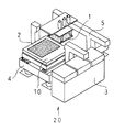
図1は、本発明のカラーフィルターの製造方法に用いるインクジェット方式によるカラーフィルター製造装置の概要を示す外観図であり、1はインクジェットヘッドユニット、2はインクジェットヘッド1がインクを付与する為の透明基板、3はインクジェットヘッド1の吐出安定性を維持するための吐出特性維持装置、4はY方向可動部(基板搬送ステージ10)の主走査方向移動装置であり、塗布の際に往復動作する。5はX方向可動部の副走査方向移動装置であり、必要幅分を透明基板2に塗布するために間歇的に送られる。インクジェットヘッドを並べたインクジェットヘッドユニット1を透明基板2と主走査方向に相対的に移動させつつ、該インクジェットヘッドからインク液を前記透明基板2に吐出して塗布を行うように構成されている。所定回数吐出を行った後に吐出特性維持装置3を用い吐出特性を安定させる。
FIG. 1 is an external view showing an outline of an ink-jet color filter manufacturing apparatus used in the color filter manufacturing method of the present invention, wherein 1 is an ink-jet head unit, and 2 is a transparent substrate on which the ink-
次に、上記塗工装置20によるカラーフィルター製造の描画工程について説明する。図1において吐出特性維持装置装置3によってインクジェットヘッドユニット1に搭載してあるインクジェットヘッドの吐出安定性を向上させる。次に副走査方向移動装置5によって透明基板2の端部にインクジェットユニット1を移動させる。そして主走査方向移動装置4により所定の回数n回(nは自然数)透明基板上で塗布させる。描画動作時の基板搬送ステージ10とインク吐出タイミングの関係は主走査方向に基板搬送ステージ10が移動し、主走査方向の位置に同期させてインクジェットヘッドのノズルよりインクの吐出を行なう。所定の回数走査させた後に副走査移動装置5により透明基板2の塗られていない部分端部に移動させ、主走査方向に移動し再度、所定の回数塗布を行う。
Next, a drawing process for producing a color filter by the
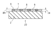
上記工程によって得られるカラーフィルターについて説明する。カラーフィルターは、インク自体を硬化して着色する方法、インク吸収性を有する樹脂等からなる受容層を透明基板2上に形成し、該受容層にインクを付与して着色する方法や透明基板2上にブラックマトリクスの溌インク性をもった土手の中にインクを付与し着色する方法などある。一例を図2、図3に、塗工装置で得られるカラーフィルター30の塗工中の模式図を示す。6は透明基板2に形成されている溌インク性を含んだブラックマトリクスであり、インクを硬化させるための障壁となる。7はR(レッド)インク滴、8はG(グリーン)インク滴、9はB(ブルー)インク滴である。本例ではR.G.Bの3色の着色部を形成する為に、3個のインクジェットヘッドを用いそれぞれブラックマトリクス6の開口部に対応してインク滴と付与しなければならない。インク吸収性を有する樹脂等からなる受容層にインクを付与する場合においても混色、吐出位置のミスディレクション等を防ぐ為に所定の場所に吐出しなくてはならない。そして、塗布されたインクはブラックマトリクス6の開口部のパターン内で濡れ広がる。
The color filter obtained by the above process will be described. For the color filter, a method for curing and coloring the ink itself, a method for forming a receiving layer made of an ink-absorbing resin or the like on the
透明基板2に塗布されたインクの平面度によりムラの要因になる事もある。インクの平面度はインクの特性である粘度、濡れ性によるところが多いが、凡そ25〜50℃において一番良い濡れ性を示す。そのインク組成によっても異なるが、例えば25℃付近においては粘度約20mPa・sであるが、40℃付近まであがると約15mPa・sまで下がり、50℃付近になると約10mPa・sまで下がる。ただし、温度を上げすぎると吐出特性が変化し、インクミストによる混色やミスディレが発生してしまうので、適正な温度にする事が重要である。塗工装置20の基板搬送ステージ10の温度をサーモによってコントロールし、そのインクにあった温度に温調する。
The flatness of the ink applied to the
図3に示すブラックマトリクス6の高さBHは約2μmであり、インクの高さIHは約1.7μmである。混色防止の為に、ブラックマトリクス6には溌インク性が含まれている。しかしながら、透明基板2の搬送の際にかかる振動、加減速、遠心力等がかかるとブラックマトリクス6を超えて混色するおそれがあり、それを防ぐ為に、搬送速度を下げるとタクトタイムに関わってきてしまう。
The height BH of the
そこで、請求項2の発明のように、透明基板2を搬出ロボットによる搬出の際に紫外線(UV光)を透明基板2上に照射する事により、その後の工程においてインクはある程度硬化しているので、基板搬送の速度上昇や回転による遠心力といった外力にも耐えられるようになる。
Therefore, as in the invention of
上記紫外線(UV光)の照射は、例えば、ピーク照度100mw/cm2 以上の超高圧水銀ランプの下を、約0.9m/minの速度で透明基板を通過させ、積算光量1100mj/cm2 以上とすることによって、透明基板上のインクを適度に硬化せしめることができる。 For example, the ultraviolet light (UV light) is irradiated under an ultra-high pressure mercury lamp having a peak illuminance of 100 mw / cm 2 or more through a transparent substrate at a rate of about 0.9 m / min, and an integrated light quantity of 1100 mj / cm 2 or more. By doing so, the ink on the transparent substrate can be appropriately cured.
1‥‥インクジェットヘッドユニット
2‥‥透明基板
3‥‥吐出特性維持装置
4‥‥主走査方向移動装置
5‥‥副走査方向移動装置
6‥‥ブラックマトリックス
7‥‥Rインク
8‥‥Gインク
9‥‥Bインク
10‥‥基板搬送ステージ
20‥‥塗工装置
30‥‥カラーフィルター
BH‥‥ブラックマトリクスの高さ
IH‥‥パターンインクの高さ
DESCRIPTION OF
Claims (2)
Priority Applications (1)
| Application Number | Priority Date | Filing Date | Title |
|---|---|---|---|
| JP2006123277A JP2007293174A (en) | 2006-04-27 | 2006-04-27 | Manufacturing method of color filter |
Applications Claiming Priority (1)
| Application Number | Priority Date | Filing Date | Title |
|---|---|---|---|
| JP2006123277A JP2007293174A (en) | 2006-04-27 | 2006-04-27 | Manufacturing method of color filter |
Publications (1)
| Publication Number | Publication Date |
|---|---|
| JP2007293174A true JP2007293174A (en) | 2007-11-08 |
Family
ID=38763849
Family Applications (1)
| Application Number | Title | Priority Date | Filing Date |
|---|---|---|---|
| JP2006123277A Pending JP2007293174A (en) | 2006-04-27 | 2006-04-27 | Manufacturing method of color filter |
Country Status (1)
| Country | Link |
|---|---|
| JP (1) | JP2007293174A (en) |
-
2006
- 2006-04-27 JP JP2006123277A patent/JP2007293174A/en active Pending
Similar Documents
| Publication | Publication Date | Title |
|---|---|---|
| CN102834188B (en) | Method of producing film by inkjet process, and film | |
| WO2016117550A1 (en) | Printer, printing method and ink | |
| US6455209B1 (en) | Color filter manufacturing method, color filter and liquid crystal displayer | |
| KR20190092240A (en) | Film forming method, Film forming apparatus, Composite substrate with film formed thereon | |
| CN117644735B (en) | Pattern forming method and ink jet printing apparatus | |
| EP1724627B1 (en) | Color filter and fabrication method thereof | |
| CN104220906B (en) | Manufacturing method of color filter and color reflective display | |
| JP2019217669A (en) | Printing method and printer | |
| JP2007293174A (en) | Manufacturing method of color filter | |
| JPWO2014030345A1 (en) | Ink-jet ink and color filter and method for producing the same, and color reflective display and method for producing the same | |
| CN100495084C (en) | Optical filter and method for manufacturing color filter | |
| JP2004145090A (en) | Manufacturing apparatus and manufacturing method for liquid crystal display device | |
| KR20090115353A (en) | Method and apparatus for selective surface modification of black matrix for flat panel display | |
| KR101038782B1 (en) | Printing apparatus for printing a printing pattern using the inkjet method and a printing method of the printing pattern | |
| JPH10282321A (en) | Method for manufacturing color filter and color filter | |
| CN100569518C (en) | Inkjet Control Method for Microfluidics | |
| JP4433246B2 (en) | Manufacturing method of color filter | |
| JP4493171B2 (en) | Manufacturing method of color filter | |
| JP2005275013A (en) | Color filter correction method and correction device | |
| JP4946129B2 (en) | Alignment device | |
| KR20070016275A (en) | A method of manufacturing a color filter having a uniform thickness by using an inkjet printhead having a solvent discharge device and solvent discharge | |
| JP4433247B2 (en) | Manufacturing method of color filter | |
| JP4023287B2 (en) | Manufacturing method of liquid crystal display device | |
| KR101734785B1 (en) | Slit nozzle coater and fabricating method of flat panel display using the same | |
| CN101430398B (en) | Method for forming optical filter |