JP2007298024A - Vane, manufacture and designing method of vane - Google Patents
Vane, manufacture and designing method of vane Download PDFInfo
- Publication number
- JP2007298024A JP2007298024A JP2007044935A JP2007044935A JP2007298024A JP 2007298024 A JP2007298024 A JP 2007298024A JP 2007044935 A JP2007044935 A JP 2007044935A JP 2007044935 A JP2007044935 A JP 2007044935A JP 2007298024 A JP2007298024 A JP 2007298024A
- Authority
- JP
- Japan
- Prior art keywords
- shell
- vane
- spar
- pressure
- suction side
- Prior art date
- Legal status (The legal status is an assumption and is not a legal conclusion. Google has not performed a legal analysis and makes no representation as to the accuracy of the status listed.)
- Pending
Links
- 238000000034 method Methods 0.000 title claims description 15
- 238000004519 manufacturing process Methods 0.000 title claims description 5
- 239000011153 ceramic matrix composite Substances 0.000 claims description 11
- 238000009826 distribution Methods 0.000 claims description 11
- 238000001816 cooling Methods 0.000 claims description 10
- 230000007423 decrease Effects 0.000 claims description 6
- 239000000919 ceramic Substances 0.000 claims description 4
- 239000011229 interlayer Substances 0.000 claims description 3
- 239000011159 matrix material Substances 0.000 claims description 3
- 239000002184 metal Substances 0.000 claims description 3
- 229910052751 metal Inorganic materials 0.000 claims description 3
- 238000011144 upstream manufacturing Methods 0.000 claims description 3
- 239000000835 fiber Substances 0.000 claims description 2
- 238000005266 casting Methods 0.000 claims 3
- 238000005058 metal casting Methods 0.000 claims 3
- 230000035882 stress Effects 0.000 abstract description 28
- 230000008646 thermal stress Effects 0.000 abstract description 5
- 239000011888 foil Substances 0.000 abstract 1
- 239000011257 shell material Substances 0.000 description 39
- 230000004048 modification Effects 0.000 description 4
- 238000012986 modification Methods 0.000 description 4
- 238000005229 chemical vapour deposition Methods 0.000 description 3
- 238000010586 diagram Methods 0.000 description 3
- 238000001764 infiltration Methods 0.000 description 3
- 230000008595 infiltration Effects 0.000 description 3
- 239000010410 layer Substances 0.000 description 3
- PXHVJJICTQNCMI-UHFFFAOYSA-N Nickel Chemical compound [Ni] PXHVJJICTQNCMI-UHFFFAOYSA-N 0.000 description 2
- 238000000626 liquid-phase infiltration Methods 0.000 description 2
- 230000007246 mechanism Effects 0.000 description 2
- 125000006850 spacer group Chemical group 0.000 description 2
- 230000008859 change Effects 0.000 description 1
- 239000000463 material Substances 0.000 description 1
- 229910001092 metal group alloy Inorganic materials 0.000 description 1
- 229910052759 nickel Inorganic materials 0.000 description 1
- 229920000642 polymer Polymers 0.000 description 1
- 238000000197 pyrolysis Methods 0.000 description 1
- 230000009467 reduction Effects 0.000 description 1
- 230000008929 regeneration Effects 0.000 description 1
- 238000011069 regeneration method Methods 0.000 description 1
- 230000003014 reinforcing effect Effects 0.000 description 1
- 238000007789 sealing Methods 0.000 description 1
- 238000005245 sintering Methods 0.000 description 1
- 239000002002 slurry Substances 0.000 description 1
- 238000007582 slurry-cast process Methods 0.000 description 1
- 238000005728 strengthening Methods 0.000 description 1
- 229910000601 superalloy Inorganic materials 0.000 description 1
- 230000007704 transition Effects 0.000 description 1
- 238000009941 weaving Methods 0.000 description 1
Images



Classifications
-
- F—MECHANICAL ENGINEERING; LIGHTING; HEATING; WEAPONS; BLASTING
- F01—MACHINES OR ENGINES IN GENERAL; ENGINE PLANTS IN GENERAL; STEAM ENGINES
- F01D—NON-POSITIVE DISPLACEMENT MACHINES OR ENGINES, e.g. STEAM TURBINES
- F01D5/00—Blades; Blade-carrying members; Heating, heat-insulating, cooling or antivibration means on the blades or the members
- F01D5/12—Blades
- F01D5/14—Form or construction
- F01D5/147—Construction, i.e. structural features, e.g. of weight-saving hollow blades
-
- F—MECHANICAL ENGINEERING; LIGHTING; HEATING; WEAPONS; BLASTING
- F01—MACHINES OR ENGINES IN GENERAL; ENGINE PLANTS IN GENERAL; STEAM ENGINES
- F01D—NON-POSITIVE DISPLACEMENT MACHINES OR ENGINES, e.g. STEAM TURBINES
- F01D5/00—Blades; Blade-carrying members; Heating, heat-insulating, cooling or antivibration means on the blades or the members
- F01D5/12—Blades
- F01D5/14—Form or construction
- F01D5/18—Hollow blades, i.e. blades with cooling or heating channels or cavities; Heating, heat-insulating or cooling means on blades
-
- F—MECHANICAL ENGINEERING; LIGHTING; HEATING; WEAPONS; BLASTING
- F01—MACHINES OR ENGINES IN GENERAL; ENGINE PLANTS IN GENERAL; STEAM ENGINES
- F01D—NON-POSITIVE DISPLACEMENT MACHINES OR ENGINES, e.g. STEAM TURBINES
- F01D5/00—Blades; Blade-carrying members; Heating, heat-insulating, cooling or antivibration means on the blades or the members
- F01D5/12—Blades
- F01D5/28—Selecting particular materials; Particular measures relating thereto; Measures against erosion or corrosion
- F01D5/282—Selecting composite materials, e.g. blades with reinforcing filaments
-
- F—MECHANICAL ENGINEERING; LIGHTING; HEATING; WEAPONS; BLASTING
- F05—INDEXING SCHEMES RELATING TO ENGINES OR PUMPS IN VARIOUS SUBCLASSES OF CLASSES F01-F04
- F05D—INDEXING SCHEME FOR ASPECTS RELATING TO NON-POSITIVE-DISPLACEMENT MACHINES OR ENGINES, GAS-TURBINES OR JET-PROPULSION PLANTS
- F05D2230/00—Manufacture
- F05D2230/30—Manufacture with deposition of material
- F05D2230/31—Layer deposition
- F05D2230/314—Layer deposition by chemical vapour deposition
-
- F—MECHANICAL ENGINEERING; LIGHTING; HEATING; WEAPONS; BLASTING
- F05—INDEXING SCHEMES RELATING TO ENGINES OR PUMPS IN VARIOUS SUBCLASSES OF CLASSES F01-F04
- F05D—INDEXING SCHEME FOR ASPECTS RELATING TO NON-POSITIVE-DISPLACEMENT MACHINES OR ENGINES, GAS-TURBINES OR JET-PROPULSION PLANTS
- F05D2300/00—Materials; Properties thereof
- F05D2300/20—Oxide or non-oxide ceramics
- F05D2300/21—Oxide ceramics
-
- F—MECHANICAL ENGINEERING; LIGHTING; HEATING; WEAPONS; BLASTING
- F05—INDEXING SCHEMES RELATING TO ENGINES OR PUMPS IN VARIOUS SUBCLASSES OF CLASSES F01-F04
- F05D—INDEXING SCHEME FOR ASPECTS RELATING TO NON-POSITIVE-DISPLACEMENT MACHINES OR ENGINES, GAS-TURBINES OR JET-PROPULSION PLANTS
- F05D2300/00—Materials; Properties thereof
- F05D2300/20—Oxide or non-oxide ceramics
- F05D2300/22—Non-oxide ceramics
- F05D2300/226—Carbides
- F05D2300/2261—Carbides of silicon
-
- F—MECHANICAL ENGINEERING; LIGHTING; HEATING; WEAPONS; BLASTING
- F05—INDEXING SCHEMES RELATING TO ENGINES OR PUMPS IN VARIOUS SUBCLASSES OF CLASSES F01-F04
- F05D—INDEXING SCHEME FOR ASPECTS RELATING TO NON-POSITIVE-DISPLACEMENT MACHINES OR ENGINES, GAS-TURBINES OR JET-PROPULSION PLANTS
- F05D2300/00—Materials; Properties thereof
- F05D2300/60—Properties or characteristics given to material by treatment or manufacturing
- F05D2300/603—Composites; e.g. fibre-reinforced
-
- Y—GENERAL TAGGING OF NEW TECHNOLOGICAL DEVELOPMENTS; GENERAL TAGGING OF CROSS-SECTIONAL TECHNOLOGIES SPANNING OVER SEVERAL SECTIONS OF THE IPC; TECHNICAL SUBJECTS COVERED BY FORMER USPC CROSS-REFERENCE ART COLLECTIONS [XRACs] AND DIGESTS
- Y02—TECHNOLOGIES OR APPLICATIONS FOR MITIGATION OR ADAPTATION AGAINST CLIMATE CHANGE
- Y02T—CLIMATE CHANGE MITIGATION TECHNOLOGIES RELATED TO TRANSPORTATION
- Y02T50/00—Aeronautics or air transport
- Y02T50/60—Efficient propulsion technologies, e.g. for aircraft
Landscapes
- Engineering & Computer Science (AREA)
- Mechanical Engineering (AREA)
- General Engineering & Computer Science (AREA)
- Chemical & Material Sciences (AREA)
- Materials Engineering (AREA)
- Composite Materials (AREA)
- Architecture (AREA)
- Turbine Rotor Nozzle Sealing (AREA)
Abstract
Description
本発明は、NASAによって締結された契約NAS3−01138のもとに米国政府の助成を得て行われたものである。米国政府は、本発明に一定の権利を有している。 This invention was made with the support of the US government under the agreement NAS3-01138 signed by NASA. The US government has certain rights in the invention.
本発明は、タービンエンジンに関する。より詳細には、本発明は、セラミックマトリックス複合材(CMC)製のタービンエンジンベーンに関する。 The present invention relates to a turbine engine. More particularly, the present invention relates to a turbine engine vane made of ceramic matrix composite (CMC).
セラミックマトリックス複合材料(CMC)は、ガスタービンエンジンにおける被冷却の固定ベーン用に提案されてきた。一例として、Morrision等の米国特許第6,514,046号明細書が挙げられる。 Ceramic matrix composites (CMC) have been proposed for cooled stationary vanes in gas turbine engines. An example is Morrision et al. US Pat. No. 6,514,046.
ベーンに対する熱負荷が高いと、熱応力、特に、層間の引張応力を最小に抑えるため、薄いシェルを有する構成となる。薄いシェルは、熱応力を制御するには十分に機能するが、シェル内部と外部のガス流との間の圧力差による機械的応力が高くなる。 When the heat load on the vane is high, the structure has a thin shell in order to minimize thermal stress, particularly tensile stress between layers. Thin shells work well to control thermal stress, but increase mechanical stress due to pressure differences between the shell internal and external gas flow.
外部の高温ガスの圧力は、前縁から後縁へと急激に低下するが、内部の冷却空気の圧力は、ほぼ一定である。そのため、シェルに亘って大きな圧力差が生じる。この圧力差により、特に負圧側において、シェルが膨張する。圧力差により、層間引張応力および軸方向応力の両方が生じる。これらの応力は、特に前縁において、設計上の最大値を超える場合がある。 The pressure of the external hot gas decreases rapidly from the leading edge to the trailing edge, but the pressure of the internal cooling air is almost constant. This creates a large pressure difference across the shell. This pressure difference causes the shell to expand, particularly on the negative pressure side. The pressure difference creates both interlayer tensile stress and axial stress. These stresses may exceed the design maximum, especially at the leading edge.
シェルを強化する一機構としては、シェルの正圧側と負圧側を連結する翼幅(スパン)方向の引張リブまたはウェブがある。リブは、圧力負荷の一部を支持するとともに、ベーンの膨張を防止する。このようなリブは、全金属製のベーンでは容易に設けることができるが、シェルの一体的な部分としてCMC製のリブを製造するのは困難である。さらに、相対的に低温のリブと高温のシェルとの間に高い引張応力が生じる場合があるため、このような構造が実現しにくくなっている。 One mechanism for strengthening the shell is a spanning rib or web that connects the pressure and suction sides of the shell. The rib supports a part of the pressure load and prevents the vane from expanding. Such ribs can be easily provided in an all-metal vane, but it is difficult to produce a CMC rib as an integral part of the shell. Furthermore, since a high tensile stress may occur between the relatively low temperature rib and the high temperature shell, such a structure is difficult to realize.
機械的負荷に対する耐性を改善するために、シェルの厚さを増加させてもよい。しかし、不利なことには、これによって、熱応力が助長されてしまう。したがって、組合せ応力を最小にする最適な壁厚が存在する。高負荷のベーンでは、それでも応力が設計限界を超えることがあり、応力を制御する他の手段が必要となる。 To improve resistance to mechanical loads, the shell thickness may be increased. However, disadvantageously, this encourages thermal stress. There is therefore an optimum wall thickness that minimizes the combined stress. With high load vanes, the stress can still exceed design limits and other means of controlling the stress are required.
さらに、応力を低下させる他の方法は、前縁における最小の曲げ半径を増加させることである。曲げ半径が大きくなると応力集中係数が低下し、したがって、応力が低下する。しかし、エアフォイルの外部形状は、空気力学的性能が最大になるように最適化されており、いかなる変更にも極めて敏感である。その結果、内径だけが増加され、実現可能な応力減少量が制限されてしまう。 Furthermore, another way to reduce the stress is to increase the minimum bend radius at the leading edge. As the bend radius increases, the stress concentration factor decreases, and therefore the stress decreases. However, the external shape of the airfoil is optimized for maximum aerodynamic performance and is extremely sensitive to any changes. As a result, only the inner diameter is increased, limiting the amount of stress reduction that can be achieved.
本発明の一態様は、エアフォイルのシェルと、このシェル内における桁と、を有するベーンを含む。ベーンは、シェルの外側端部における外側シュラウドと、シェルの内側端部における内側プラットフォームと、を有する。桁は、実質的に負圧側面に沿った第1のチャンバと、第1のチャンバに対向する、正圧側面に沿った第2のチャンバと、を有する。 One aspect of the present invention includes a vane having an airfoil shell and a girder within the shell. The vane has an outer shroud at the outer end of the shell and an inner platform at the inner end of the shell. The spar has a first chamber substantially along the suction side and a second chamber along the pressure side opposite the first chamber.
添付図面および以下の記載により、本発明の1つまたは複数の実施形態の詳細を説明する。本発明の他の特徴、目的および利点は、実施例、図面および特許請求の範囲から明らかになるであろう。 The details of one or more embodiments of the invention are set forth in the accompanying drawings and the description below. Other features, objects, and advantages of the invention will be apparent from the examples and drawings, and from the claims.
図面における数字および符号が同じ場合には同じ要素を示している。 The same elements are denoted by the same numerals and symbols in the drawings.
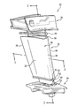
図1は、ベーン20を図示しており、ベーン20は、内側のプラットフォーム24における内側端部から外側のシュラウド26における外側端部まで延びるエアフォイル22を有する。エアフォイル22は、前縁28、後縁30、ならびに前縁と後縁との間に延在する正圧側面32および負圧側面34を有する。例示したプラットフォームおよびシュラウドは、円環の一部分であり、このようなシュラウドおよびプラットフォームの端部を互いに密着/結合させることにより、周方向のベーンの列が形成される。
FIG. 1 illustrates a
例示的なベーン20は、シュラウド、プラットフォームおよびエアフォイルを別々に形成して、互いに固定したアッセンブリである。図1〜3では、薄い壁部を有するシェル50と、該シェル内における構造的な桁52と、を備えたエアフォイルが図示されている。例示的なシェルの材料は、セラミックマトリックス複合材料(CMC)である。シェルは、様々なCMC作製方法によって製造することができる。前記方法には、通常、セラミック繊維(例えば、SiC)のプリフォームをエアフォイル形状に成形すること(例えば、編織または他の技法によって)、およびプリフォームにマトリックス材(例えば、SiC)を溶浸(インフィルトレーション)させることが含まれる。溶浸に先立って、マトリックスとの接着を制限するために、プリフォームにコーティングを施してもよい(例えば、化学蒸着法(CVD)によるBNで)。例示的な溶浸法には、化学気相析出法、スラリ溶浸焼結法(slurry infiltration-sintering)、ポリマー含浸−熱分解法(polymer-impregnation-pyrolysis)、スラリキャスト法、溶融溶浸法(melt infiltration)が含まれる。例示的な桁の材料は、金属合金(例えば、鋳造ニッケルベースの超合金)である。内側シール53および外側シール54は、それぞれシェルの内側端部55と隣接するプラットフォームとの間、および外側端部56と隣接するシュラウドとの間をシールする。
The
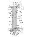
桁52の外側端部40(図2)は、シュラウド26に取り付けられる。図2の例では、この外側端部40は、面42によって形成された開口部に受容されて、溶接される。ねじ付きスタッド44は、桁52の内側端部に形成され、面45によって形成されたプラットフォーム24の開口部を通って延びている。ナット46および座金47は、スタッドおよびプラットフォームの内側面に係合し、桁52の肩部48は、プラットフォームの肩部49と接合する。このように、桁52によって、シュラウド26とプラットフォーム24との間における主要な機械的連結部分が形成される。
The outer end 40 (FIG. 2) of the
シェルは、桁に対して、複数の機構のうち1つまたは複数の機構によって位置決めされる。シェルのフランジ(端部)55,56は、適切なプラットフォームのチャネル57(図1)、およびシュラウドのチャネル58(図2)によってそれぞれ位置決めされる。シール53,54などのスペーサまたはシール/スペーサユニットが、桁とシェルとの間に配置される。
The shell is positioned relative to the girder by one or more of a plurality of mechanisms. The shell flanges (ends) 55, 56 are positioned by a suitable platform channel 57 (FIG. 1) and a shroud channel 58 (FIG. 2), respectively. Spacers such as
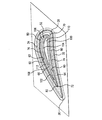
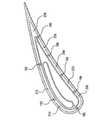
シェルの外側面(図3)は、前縁28、後縁30、正圧側面32および負圧側面34を画定する。シェルの内側面は、正圧側面に沿った第1の部分60と、負圧側面に沿った第2の部分62と、を有する。前記第1および第2の部分により、隣接する正圧側壁部64および負圧側壁部66がそれぞれ画定され、正圧側壁部64および負圧側壁部66は、前縁においては直接的に一体となり、後縁においては後縁に向かって次第に一体となる。
The outer surface of the shell (FIG. 3) defines a leading
桁52の外側面は、シェルの内側面に対して近接離間して対面している。したがって、桁の外側面は、前縁70、後縁72、正圧側部分74および負圧側部分76を有する。1つまたは複数のシール80,82が、桁の外側面とシェルの内側面との間において概ね翼幅(スパン)方向に延びて配設されている。例示的な2つのシールにより、シェルと桁との間のキャビティが、第1のキャビティ90と第2のキャビティ92とに分割される。キャビティ90,92には、桁52内のチャンバ/キャビティ/プレナム(以下で説明)から空気が供給される。
The outer surface of the
例示的な桁52は、正圧側部分100および負圧側部分102を備えた側壁を有する。例示的な桁52は、内壁部104を有し、この内壁部104は、桁の前縁に隣接した桁の側壁と連結している第1の連結部106から、桁の正圧側面100の後縁部分に沿った桁の側壁と連結している第2の連結部108まで延びている。したがって、この内壁部104により、桁の内部が、第1のチャンバ110と第2のチャンバ112とに分割される。
The
例示的な第1のチャンバ110は、実質的に、桁の正圧側面の半分以上に亘って延びている。例示的な第2のチャンバ112は、桁の負圧側面のほぼ全体に亘って延びている。これらのチャンバ110,112は、桁の側壁に配設された微小な開口部の列(図示せず)を介して、隣接するキャビティ90,92に冷却空気を供給する。キャビティ90,92に導入された空気は、実質的に下流方向に(後縁に向かって)流れ、シェルの後縁出口(図示せず)から流出する。したがって、このような流れのため、空気は1つまたは両方のシールから漏出する(例えば、キャビティ90からの空気はシール80から漏出する)。
The exemplary
チャンバ110,112には、プラットフォームおよびシュラウドの一方または両方における対応のポートを介して冷却空気が供給される。図2には、第2のチャンバ112に空気を供給するプラットフォームの第1のポート114と、第1のチャンバ110に空気を供給するシュラウドおよび桁の外側端部の第2のポート116と、が図示されている。以下に説明するように、異なった圧力および/または温度の空気を2つのチャンバ110,112に導入することができるため、熱応力および機械的応力を効果的に低減させるように、キャビティ90,92における適切な空気流量、温度および圧力をより柔軟に選択することが可能となる。
Cooling air is supplied to the
図4は、シェルに沿った例示的な翼幅方向位置における、流れ方向の圧力分布を示す。エアフォイルの正圧側面32に沿った外部圧力を420、負圧側面34に沿った外部圧力を422として示す。前縁28において、これらの圧力は、よどみ点圧力に統合される。内部圧力は、桁の開口部を通るときに絞られることに鑑みて、冷却供給圧力の関数であり得る。シール80,82、および複数のチャンバを有する桁が存在しない場合には、内部圧力は、シェルの正圧側面および負圧側面に亘って実質的に一定となる(例えば、流れ損失による上流から下流への僅かな減少を伴う)。例えば、内部圧力をよどみ点圧力より僅かに高くする(例えば、シェルにクラックが生じた場合に高温ガスを吸い込むのを回避するために2〜3%)。しかし、内部圧力と外部圧力との差により、シェルの設計閾値を超える機械的応力(および熱応力)が生じてしまう。
FIG. 4 shows the pressure distribution in the flow direction at an exemplary span position along the shell. External pressure along the
桁とシェルとの間における複数のキャビティ90,92を形成するシール80,82を備えることにより、シェルにおける異なった位置において、異なった内部圧力を維持することが可能になる。異なった空気が(例えば、異なった温度および/または圧力で)供給される桁のチャンバ110,112を介してキャビティに空気を供給することによって、キャビティに沿ったシェルの冷却量から各キャビティ90,92内の圧力を少なくとも部分的にさらに切り離することにより、付加的な柔軟性がもたらされる。例えば、例示的な図3の形態では、シェルの正圧側部分の全体が第1のキャビティに沿っているため、正圧側の内部圧力424は、実質的に一定に保たれる。しかし、負圧側の内部圧力426は、第2のキャビティと関連する領域において低下する。これにより、この負圧側内部圧力426が、機械的応力成分を低減させるように、外部圧力422に対してより緊密に対応することができる。図4では、内部圧力に関する前縁からの距離は、桁の外面に沿った距離である。
By having
そのような圧力分布を実現するために、一実施例においては、第2のチャンバ112への圧力を、第1のチャンバ110への圧力より低くすることができる。例えば、例示的な圧力差は、少なくとも5psi(例えば、5〜50psi、より具体的には、5〜10psi)である。百分率換算では、この圧力差は、少なくとも1.5%(例えば、1.5〜15%)である。他の任意選択的な同様の例では、第2のチャンバ112には、1つまたは複数の相対的に前方/上流側の圧縮機の段から抽気を行い、第1のチャンバ110には、圧力および温度がより高い後方/下流側の圧縮機の段から抽気を行ってもよい。
In order to achieve such a pressure distribution, in one embodiment, the pressure on the
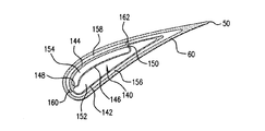
図5は、別の実施例の桁140を図示しており、この桁140は、正圧側部分142および負圧側部分144を有する側壁を備える。例示的な桁140は、内壁部146を有し、この内壁部146は、桁の前縁に隣接した桁の側壁と連結している第1の連結部148から、負圧側面144に沿った桁の側壁と連結している第2の連結部150まで延びている。この内壁部146により、桁の内部が、第1のチャンバ152と第2のチャンバ154とに分割される。例示的な第1のチャンバ152は、実質的に、正圧側全体に亘っており、かつ僅かに負圧側の前縁および後縁部分に亘って延びている。例示的な第2のチャンバ154の全体は、実質的に桁の負圧側に亘って延びている。これらのチャンバ152,154により、隣接するキャビティ156,158に冷却空気が供給される。例示的なキャビティは、シール160,162によって分割され、図3の実施形態の各キャビティと同様に空気が供給される。第1のシール160は、前縁から僅かに負圧側に配置されている。第2のシール162は、負圧側に沿った中間位置(例えば、負圧側に沿って流れ方向の長さの約50%〜70%)に配置されている。
FIG. 5 illustrates another
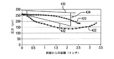
図6は、図5のエアフォイルに関する正圧側の内部圧力430および負圧側の内部圧力432を示している。第2のシール162が存在することによって、負圧側圧力432が急激な上昇434を示し、第2のシール162の下流における正圧側の分布に実質的に同化する。
FIG. 6 shows the
さらなる変更形態として、図7には、図5と同様のシェルおよび桁を有するエアフォイルが図示されているが、このエアフォイルは、より多くのキャビティを形成する多数のシールを備えている。図7の実施例では、シール180,182は、図5のシール160,162と同様に配置されている。しかし、関連するキャビティの各々は、正圧側面に沿ったシール184,186,188,190のグループ、および負圧側面に沿った例示的な単一のシール192によって、さらに分割されている。したがって、キャビティ156(図5)が、一連のキャビティ200,202,204,206,208に、キャビティ158(図5)が、1対のキャビティ210,212にそれぞれ変更されている。他の変更形態には、シール180,182の位置変更や桁のチャンバの構成変更が含まれる。シールの配置、シールの封止係合の堅牢性(制御下での漏洩を含む)、および桁のチャンバからの供給孔の分布によって、各キャビティ内および各キャビティに沿った圧力分布をさらに調整することが可能となる。
As a further modification, FIG. 7 illustrates an airfoil having a shell and spar similar to that of FIG. 5, but the airfoil includes multiple seals that form more cavities. In the embodiment of FIG. 7, the
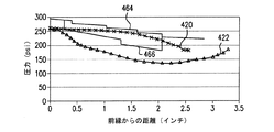
図8には、基本的な外部圧力420,422が示されている。図7のエアフォイルの正圧側の内部圧力464および負圧側の内部圧力466は、図6の圧力に比べて、より多くの段階(ステップ)を示している。これらの段階は、キャビティからキャビティへの移行に対応しており、シェルの壁部に亘る圧力差をさらに低下させるように、関連する外部圧力に対して圧力分布をより緊密に対応させることが可能となる。
FIG. 8 shows basic
本発明は、所与のベーンを再設計する際に実施可能である。再設計は、シェルの基本的な外部形状を保つことができる。再設計は、内部形状を保つこともできる。ただし、実現可能な応力軽減に鑑みて、壁の薄肉化を含む内部変更がとりわけ適切である。このようにして、再設計は、また、引張リブ/ウェブ、局部的な肉厚領域など、他の内部強化特徴部を排除することができる。また、再設計は、桁の構造をより実質的に変更することができる。適切な桁のチャンバを設けることに加えて、再設計は、複数部片の桁を、単一部片の桁に置き換えることができる。再設計は、単一の桁と非構造的な充填部品の組合せを、単一の桁に置き換えることができる。再設計されたベーンは、所与のガスタービンエンジンの再生に使用することができる。 The present invention can be implemented in redesigning a given vane. Redesign can preserve the basic external shape of the shell. Redesign can also preserve the internal shape. However, in view of the possible stress relief, internal modifications including wall thinning are particularly appropriate. In this way, the redesign can also eliminate other internal reinforcing features such as tensile ribs / webs, localized wall thickness regions. Also, the redesign can change the structure of the girder more substantially. In addition to providing an appropriate spar chamber, the redesign can replace a multi-part spar with a single-part spar. Redesign can replace the combination of a single girder and an unstructured filling part with a single girder. The redesigned vanes can be used to regenerate a given gas turbine engine.
再設計の予測例として、図9は、よどみ点圧力より僅かに高い実質的に一定な内部圧力を有する基準となるエアフォイルのシェルの前縁部分に沿った軸方向の応力を示す。図10は、層間の引張応力を示す。 As a predictive example of redesign, FIG. 9 shows the axial stress along the leading edge portion of a reference airfoil shell having a substantially constant internal pressure slightly higher than the stagnation point pressure. FIG. 10 shows the tensile stress between the layers.
図11および図12は、基準となるベーンの圧力分布に対して内部圧力が30%低下した、対応する軸方向応力および層間の引張応力をそれぞれ示す。応力の最大値が、大幅に減少していることが分かる。 11 and 12 show the corresponding axial stress and interlaminar tensile stress, respectively, with the internal pressure reduced by 30% relative to the reference vane pressure distribution. It can be seen that the maximum value of the stress is greatly reduced.
本発明の1つまたは複数の実施形態について説明してきた。しかし、本発明の精神および範囲から逸脱することなく、様々な変更を加えることができることは理解されよう。例えば、既存のベーン構成の再設計(例えば、エンジンの再生またはエンジン構成の再設計の一部として)として実行される際、基準のエンジン構成またはベーン構成の細部が、個々の実装形態の細部に影響を及ぼし得る。したがって、他の実施形態も、添付の特許請求の範囲に包含される。 One or more embodiments of the present invention have been described. However, it will be understood that various modifications may be made without departing from the spirit and scope of the invention. For example, when implemented as a redesign of an existing vane configuration (e.g., as part of engine regeneration or engine design redesign), the details of the reference engine configuration or vane configuration become the details of individual implementation May have an impact. Accordingly, other embodiments are within the scope of the appended claims.
Claims (19)
前記シェル内における桁と、
前記シェルの外側端部における外側シュラウドと、
前記シェルの内側端部に内側プラットフォームと、
を備えるベーンであって、
前記桁が、
前記負圧側面に実質的に沿った第1のチャンバと、
前記第1のチャンバに対向する、前記正圧側面に沿った第2のチャンバと、
を備えることを特徴とするベーン。 An airfoil shell having a leading edge, a trailing edge, a pressure side and a suction side;
A digit in the shell;
An outer shroud at the outer end of the shell;
An inner platform at the inner end of the shell;
A vane comprising:
The digit is
A first chamber substantially along the suction side;
A second chamber along the pressure side facing the first chamber;
Vane characterized by comprising.
前記桁が、実質的に第1の金属鋳造物からなり、
前記プラットフォームが、実質的に第2の金属鋳造物からなり、
前記シュラウドが、実質的に第3の金属鋳造物からなることを特徴とする請求項1に記載のベーン。 The airfoil shell consists essentially of a ceramic matrix composite;
Said spar consists essentially of a first metal casting,
The platform substantially consists of a second metal casting;
The vane according to claim 1, wherein the shroud consists essentially of a third metal casting.
前縁と、
後縁と、
正圧側面と、
負圧側面と、
を有する側壁を備え、
前記シェルが、前記シェルの正圧側面と負圧側面とを連結する引張ウェブを有していないことを特徴とする請求項1に記載のベーン。 The digit is
The leading edge,
The trailing edge,
The pressure side,
The suction side,
A sidewall having
The vane according to claim 1, wherein the shell does not have a tensile web that connects the pressure side and the suction side of the shell.
前縁と、
後縁と、
正圧側面と、
負圧側面と、
を有する側壁を備え、
前記桁の第1のチャンバが、前記桁の前縁付近から前記負圧側面における前記桁の側壁まで延在する壁によって形成されることを特徴とする請求項1に記載のベーン。 The digit is
The leading edge,
The trailing edge,
The pressure side,
The suction side,
A sidewall having
2. A vane according to claim 1, wherein the first chamber of the spar is formed by a wall extending from near the leading edge of the spar to the side wall of the spar at the suction side.
前記シュラウドを鋳造するステップと、
前記プラットフォームを鋳造するステップと、
前記桁を鋳造するステップと、
前記シェルを形成するように、セラミック繊維のプリフォームにセラミックマトリックスを溶浸させるステップと、
を含むベーン製造方法。 A method for producing the vane according to claim 1, comprising:
Casting the shroud;
Casting the platform;
Casting the beam;
Infiltrating a ceramic matrix into a ceramic fiber preform to form the shell;
A vane manufacturing method including:
第1の空気流を前記第1のチャンバに導くステップと、
前記第1の空気流と異なった温度および圧力の少なくとも一方を有する第2の空気流を前記第2のチャンバに導くステップと、
を含むベーン冷却方法。 A method for cooling a vane according to claim 1, comprising:
Directing a first air stream to the first chamber;
Directing a second air stream having at least one of a temperature and a pressure different from the first air stream to the second chamber;
Including vane cooling method.
前記シェル内における桁と、
前記シェルの外側端部における外側シュラウドと、
前記シェルの内側端部に内側プラットフォームと、
を備えるベーンであって、
前記桁が、前記桁内に、前記シェルに対する熱的機械的応力を制限する多重チャンバ手段を備えることを特徴とするベーン。 An airfoil shell having a leading edge, a trailing edge, a pressure side and a suction side;
A digit in the shell;
An outer shroud at the outer end of the shell;
An inner platform at the inner end of the shell;
A vane comprising:
A vane wherein the spar comprises multiple chamber means within the spar for limiting thermal mechanical stress on the shell.
前記シュラウドにおける第2の空気ポートと、
をさらに備える請求項13に記載のベーン。 A first air port in the platform;
A second air port in the shroud;
The vane according to claim 13, further comprising:
前記桁が、金属であることを特徴とする請求項13に記載のベーン。 The shell is a ceramic matrix composite (CMC);
The vane according to claim 13, wherein the girder is a metal.
前記シェル内における桁と、
前記シェルの外側端部における外側シュラウドと、
前記シェルの内側端部に内側プラットフォームと、
を有するベーンを設計する方法であって、
前記シェル内に所望の内部圧力分布をもたらすように前記桁と前記シェルとの間のキャビティに空気流を供給するために、前記桁内に複数のチャンバを形成するステップを含むことを特徴とするベーン設計方法。 An airfoil shell having a leading edge, a trailing edge, a pressure side and a suction side;
A digit in the shell;
An outer shroud at the outer end of the shell;
An inner platform at the inner end of the shell;
A method for designing a vane having
Forming a plurality of chambers in the spar to provide an air flow to a cavity between the spar and the shell to provide a desired internal pressure distribution in the shell. Vane design method.
正の軸方向応力、負の軸方向応力、正の層間引張応力および負の層間引張応力の作動中の最大絶対値が、全て、前記基準となる構成から前記再設計された構成にかけて、少なくとも50%減少することを特徴とする請求項16に記載のベーン設計方法。 The method is a redesign from a reference configuration to a redesigned configuration,
Maximum absolute values during operation of positive axial stress, negative axial stress, positive interlayer tensile stress and negative interlayer tensile stress are all at least 50 from the baseline configuration to the redesigned configuration. The vane design method according to claim 16, wherein the vane design method decreases by%.
前記シェルが、前記基準となる構成から前記再設計された構成にかけて、前記シェルの前方10分の1に沿った少なくとも1つの箇所において薄肉化されることを特徴とする請求項16に記載のベーン設計方法。 The method is a redesign from a reference configuration to a redesigned configuration,
The vane according to claim 16, wherein the shell is thinned at at least one point along the front tenth of the shell from the reference configuration to the redesigned configuration. Design method.
Applications Claiming Priority (1)
| Application Number | Priority Date | Filing Date | Title |
|---|---|---|---|
| US11/417,972 US7452189B2 (en) | 2006-05-03 | 2006-05-03 | Ceramic matrix composite turbine engine vane |
Publications (1)
| Publication Number | Publication Date |
|---|---|
| JP2007298024A true JP2007298024A (en) | 2007-11-15 |
Family
ID=38356211
Family Applications (1)
| Application Number | Title | Priority Date | Filing Date |
|---|---|---|---|
| JP2007044935A Pending JP2007298024A (en) | 2006-05-03 | 2007-02-26 | Vane, manufacture and designing method of vane |
Country Status (3)
| Country | Link |
|---|---|
| US (1) | US7452189B2 (en) |
| EP (1) | EP1852572B1 (en) |
| JP (1) | JP2007298024A (en) |
Cited By (6)
| Publication number | Priority date | Publication date | Assignee | Title |
|---|---|---|---|---|
| WO2010110327A1 (en) * | 2009-03-26 | 2010-09-30 | 株式会社Ihi | Cmc turbine stator vane |
| WO2010110325A1 (en) * | 2009-03-26 | 2010-09-30 | 株式会社Ihi | Cmc turbine stator vane |
| JP2012137086A (en) * | 2010-12-27 | 2012-07-19 | General Electric Co <Ge> | Turbine airfoil component containing ceramic-based material, and process therefor |
| JP2015522752A (en) * | 2012-06-29 | 2015-08-06 | ゼネラル・エレクトリック・カンパニイ | Nozzles, nozzle hangers, and ceramic-metal mounting systems |
| JP2017187029A (en) * | 2016-04-01 | 2017-10-12 | ゼネラル・エレクトリック・カンパニイ | Turbine device and redundant cooling method for turbine device |
| JP2018021544A (en) * | 2016-06-06 | 2018-02-08 | ゼネラル・エレクトリック・カンパニイ | Turbine component and method of making and cooling turbine component |
Families Citing this family (80)
| Publication number | Priority date | Publication date | Assignee | Title |
|---|---|---|---|---|
| US8528339B2 (en) * | 2007-04-05 | 2013-09-10 | Siemens Energy, Inc. | Stacked laminate gas turbine component |
| DE102007027465A1 (en) | 2007-06-14 | 2008-12-18 | Rolls-Royce Deutschland Ltd & Co Kg | Gas turbine blade with modular construction |
| US8206118B2 (en) * | 2008-01-04 | 2012-06-26 | United Technologies Corporation | Airfoil attachment |
| US8142163B1 (en) * | 2008-02-01 | 2012-03-27 | Florida Turbine Technologies, Inc. | Turbine blade with spar and shell |
| US20090202355A1 (en) * | 2008-02-11 | 2009-08-13 | Rolls-Royce North American Technologies, Inc. | Replaceable blade tip shroud |
| US8956105B2 (en) * | 2008-12-31 | 2015-02-17 | Rolls-Royce North American Technologies, Inc. | Turbine vane for gas turbine engine |
| US8251651B2 (en) | 2009-01-28 | 2012-08-28 | United Technologies Corporation | Segmented ceramic matrix composite turbine airfoil component |
| JP5107463B2 (en) * | 2009-05-11 | 2012-12-26 | 三菱重工業株式会社 | Turbine vane and gas turbine |
| EP2295722B1 (en) | 2009-09-09 | 2019-11-06 | Ansaldo Energia IP UK Limited | Blade of a turbine |
| US8511969B2 (en) * | 2009-10-01 | 2013-08-20 | Pratt & Whitney Canada Corp. | Interturbine vane with multiple air chambers |
| US9890647B2 (en) * | 2009-12-29 | 2018-02-13 | Rolls-Royce North American Technologies Inc. | Composite gas turbine engine component |
| US9080448B2 (en) * | 2009-12-29 | 2015-07-14 | Rolls-Royce North American Technologies, Inc. | Gas turbine engine vanes |
| US8790067B2 (en) | 2011-04-27 | 2014-07-29 | United Technologies Corporation | Blade clearance control using high-CTE and low-CTE ring members |
| FR2974593B1 (en) * | 2011-04-28 | 2015-11-13 | Snecma | TURBINE ENGINE COMPRISING A METAL PROTECTION OF A COMPOSITE PIECE |
| US8864492B2 (en) | 2011-06-23 | 2014-10-21 | United Technologies Corporation | Reverse flow combustor duct attachment |
| US8739547B2 (en) | 2011-06-23 | 2014-06-03 | United Technologies Corporation | Gas turbine engine joint having a metallic member, a CMC member, and a ceramic key |
| US9726028B2 (en) | 2011-06-29 | 2017-08-08 | Siemens Energy, Inc. | Ductile alloys for sealing modular component interfaces |
| US8511975B2 (en) | 2011-07-05 | 2013-08-20 | United Technologies Corporation | Gas turbine shroud arrangement |
| US9335051B2 (en) | 2011-07-13 | 2016-05-10 | United Technologies Corporation | Ceramic matrix composite combustor vane ring assembly |
| US8920127B2 (en) | 2011-07-18 | 2014-12-30 | United Technologies Corporation | Turbine rotor non-metallic blade attachment |
| WO2013144024A1 (en) | 2012-03-28 | 2013-10-03 | Alstom Technology Ltd | Method for separating a metal part from a ceramic part |
| WO2013144035A1 (en) | 2012-03-28 | 2013-10-03 | Alstom Technology Ltd | Method for processing a modular hybrid component |
| EP2956625B1 (en) | 2013-02-18 | 2017-11-29 | United Technologies Corporation | Stress mitigation feature for composite airfoil leading edge |
| WO2014158277A2 (en) | 2013-03-04 | 2014-10-02 | Freeman Ted J | Method for making gas turbine engine ceramic matrix composite airfoil |
| CA2901835A1 (en) * | 2013-03-04 | 2014-10-02 | Rolls-Royce North American Technologies, Inc. | Compartmentalization of cooling air flow in a structure comprising a cmc component |
| CA2899891A1 (en) * | 2013-03-14 | 2014-10-02 | Adam L. CHAMBERLAIN | Bi-cast turbine vane |
| US10590798B2 (en) | 2013-03-25 | 2020-03-17 | United Technologies Corporation | Non-integral blade and platform segment for rotor |
| US10145245B2 (en) * | 2013-09-24 | 2018-12-04 | United Technologies Corporation | Bonded multi-piece gas turbine engine component |
| DE102013219774A1 (en) * | 2013-09-30 | 2015-04-02 | MTU Aero Engines AG | Shovel for a gas turbine |
| US9896943B2 (en) * | 2014-05-12 | 2018-02-20 | Honeywell International Inc. | Gas path components of gas turbine engines and methods for cooling the same using porous medium cooling systems |
| US10094239B2 (en) * | 2014-10-31 | 2018-10-09 | Rolls-Royce North American Technologies Inc. | Vane assembly for a gas turbine engine |
| US10202854B2 (en) | 2014-12-18 | 2019-02-12 | Rolls-Royce North America Technologies, Inc. | Abrasive tips for ceramic matrix composite blades and methods for making the same |
| US9995160B2 (en) * | 2014-12-22 | 2018-06-12 | General Electric Company | Airfoil profile-shaped seals and turbine components employing same |
| EP3048254B1 (en) * | 2015-01-22 | 2017-12-27 | Rolls-Royce Corporation | Vane assembly for a gas turbine engine |
| US10329950B2 (en) * | 2015-03-23 | 2019-06-25 | Rolls-Royce North American Technologies Inc. | Nozzle guide vane with composite heat shield |
| US9915151B2 (en) | 2015-05-26 | 2018-03-13 | Rolls-Royce Corporation | CMC airfoil with cooling channels |
| US10294807B2 (en) | 2016-05-19 | 2019-05-21 | Honeywell International Inc. | Inter-turbine ducts |
| US10746038B2 (en) * | 2016-11-17 | 2020-08-18 | Raytheon Technologies Corporation | Airfoil with airfoil piece having radial seal |
| US10436062B2 (en) * | 2016-11-17 | 2019-10-08 | United Technologies Corporation | Article having ceramic wall with flow turbulators |
| US10260363B2 (en) * | 2016-12-08 | 2019-04-16 | General Electric Company | Additive manufactured seal for insert compartmentalization |
| US10767502B2 (en) | 2016-12-23 | 2020-09-08 | Rolls-Royce Corporation | Composite turbine vane with three-dimensional fiber reinforcements |
| US10851658B2 (en) | 2017-02-06 | 2020-12-01 | General Electric Company | Nozzle assembly and method for forming nozzle assembly |
| US10724380B2 (en) * | 2017-08-07 | 2020-07-28 | General Electric Company | CMC blade with internal support |
| FR3070422B1 (en) | 2017-08-22 | 2021-07-23 | Safran Aircraft Engines | DAGGER ATTACHMENT WITH STRAIGHTENER VANE SEAL |
| US11346246B2 (en) * | 2017-12-01 | 2022-05-31 | Siemens Energy, Inc. | Brazed in heat transfer feature for cooled turbine components |
| US10697310B2 (en) * | 2018-05-17 | 2020-06-30 | Raytheon Technologies Corporation | Multiple source impingement baffles for gas turbine engine components |
| US10612399B2 (en) * | 2018-06-01 | 2020-04-07 | Rolls-Royce North American Technologies Inc. | Turbine vane assembly with ceramic matrix composite components |
| US10808560B2 (en) * | 2018-06-20 | 2020-10-20 | Rolls-Royce Corporation | Turbine vane assembly with ceramic matrix composite components |
| US11008888B2 (en) * | 2018-07-17 | 2021-05-18 | Rolls-Royce Corporation | Turbine vane assembly with ceramic matrix composite components |
| US11149567B2 (en) | 2018-09-17 | 2021-10-19 | Rolls-Royce Corporation | Ceramic matrix composite load transfer roller joint |
| US11820716B2 (en) | 2018-10-18 | 2023-11-21 | Rolls Royce North American Technologies Inc. | Method of fabricating cooling features on a ceramic matrix composite (CMC) component |
| US11046620B2 (en) | 2018-10-18 | 2021-06-29 | Rolls-Royce Corporation | Method of processing a ceramic matrix composite (CMC) component |
| US10752556B2 (en) | 2018-10-18 | 2020-08-25 | Rolls-Royce High Temperature Composites Inc. | Method of processing a ceramic matrix composite (CMC) component |
| US10906842B2 (en) | 2018-10-18 | 2021-02-02 | Rolls-Royce High Temperature Composites Inc. | Method of processing a ceramic matrix composite (CMC) component |
| US11149568B2 (en) | 2018-12-20 | 2021-10-19 | Rolls-Royce Plc | Sliding ceramic matrix composite vane assembly for gas turbine engines |
| US20200248568A1 (en) * | 2019-02-01 | 2020-08-06 | Rolls-Royce Plc | Turbine vane assembly with ceramic matrix composite components and temperature management features |
| US10767495B2 (en) * | 2019-02-01 | 2020-09-08 | Rolls-Royce Plc | Turbine vane assembly with cooling feature |
| US10975708B2 (en) * | 2019-04-23 | 2021-04-13 | Rolls-Royce Plc | Turbine section assembly with ceramic matrix composite vane |
| US11193381B2 (en) | 2019-05-17 | 2021-12-07 | Rolls-Royce Plc | Turbine vane assembly having ceramic matrix composite components with sliding support |
| US10890076B1 (en) | 2019-06-28 | 2021-01-12 | Rolls-Royce Plc | Turbine vane assembly having ceramic matrix composite components with expandable spar support |
| US11286798B2 (en) | 2019-08-20 | 2022-03-29 | Rolls-Royce Corporation | Airfoil assembly with ceramic matrix composite parts and load-transfer features |
| US11149560B2 (en) | 2019-08-20 | 2021-10-19 | Rolls-Royce Plc | Airfoil assembly with ceramic matrix composite parts and load-transfer features |
| EP3805525A1 (en) | 2019-10-09 | 2021-04-14 | Rolls-Royce plc | Turbine vane assembly incorporating ceramic matric composite materials |
| US11255204B2 (en) | 2019-11-05 | 2022-02-22 | Rolls-Royce Plc | Turbine vane assembly having ceramic matrix composite airfoils and metallic support spar |
| US11156105B2 (en) * | 2019-11-08 | 2021-10-26 | Raytheon Technologies Corporation | Vane with seal |
| US11174794B2 (en) * | 2019-11-08 | 2021-11-16 | Raytheon Technologies Corporation | Vane with seal and retainer plate |
| US10975709B1 (en) | 2019-11-11 | 2021-04-13 | Rolls-Royce Plc | Turbine vane assembly with ceramic matrix composite components and sliding support |
| US11454127B2 (en) * | 2019-11-22 | 2022-09-27 | Pratt & Whitney Canada Corp. | Vane for gas turbine engine |
| FR3107299B1 (en) | 2020-02-14 | 2022-03-11 | Safran Aircraft Engines | Vane made of composite material for a turbomachine stator comprising a hollow core made of non-porous plastic |
| US11391163B1 (en) * | 2021-03-05 | 2022-07-19 | Raytheon Technologies Corporation | Vane arc segment with seal |
| US11536145B2 (en) * | 2021-04-09 | 2022-12-27 | Raytheon Technologies Corporation | Ceramic component with support structure |
| US11549385B2 (en) * | 2021-05-04 | 2023-01-10 | Raytheon Technologies Corporation | Airfoil assembly with seal plate and seal |
| US11519280B1 (en) | 2021-09-30 | 2022-12-06 | Rolls-Royce Plc | Ceramic matrix composite vane assembly with compliance features |
| US11560799B1 (en) | 2021-10-22 | 2023-01-24 | Rolls-Royce High Temperature Composites Inc. | Ceramic matrix composite vane assembly with shaped load transfer features |
| US11591921B1 (en) | 2021-11-05 | 2023-02-28 | Rolls-Royce Plc | Ceramic matrix composite vane assembly |
| US11732596B2 (en) | 2021-12-22 | 2023-08-22 | Rolls-Royce Plc | Ceramic matrix composite turbine vane assembly having minimalistic support spars |
| US11773737B1 (en) | 2022-04-29 | 2023-10-03 | Rolls-Royce Plc | Load transfer device, stator vane assembly, turbine, and gas turbine engine including the same |
| US12292242B2 (en) | 2022-05-26 | 2025-05-06 | Hamilton Sundstrand Corporation | Surface texture enhanced glass-ceramic matrix composite heat exchanger |
| US11802487B1 (en) * | 2022-08-15 | 2023-10-31 | Rtx Corporation | Gas turbine engine stator vane formed of ceramic matrix composites and having attachment flanges |
| US12571321B2 (en) * | 2023-08-24 | 2026-03-10 | Rtx Corporation | Radial seal between CMC vane and vane support |
Citations (3)
| Publication number | Priority date | Publication date | Assignee | Title |
|---|---|---|---|---|
| US4312624A (en) * | 1980-11-10 | 1982-01-26 | United Technologies Corporation | Air cooled hollow vane construction |
| JPS58119902A (en) * | 1981-12-31 | 1983-07-16 | ウエスチングハウス エレクトリック コ−ポレ−ション | Forced cooling type fluid directional blade-shaped member for combustion turbine |
| JPS6189908A (en) * | 1984-10-11 | 1986-05-08 | Central Res Inst Of Electric Power Ind | Ceramics-metal composite vane structure |
Family Cites Families (22)
| Publication number | Priority date | Publication date | Assignee | Title |
|---|---|---|---|---|
| US2497041A (en) * | 1945-03-27 | 1950-02-07 | United Aircraft Corp | Nozzle ring for gas turbines |
| US3240468A (en) * | 1964-12-28 | 1966-03-15 | Curtiss Wright Corp | Transpiration cooled blades for turbines, compressors, and the like |
| US3963368A (en) * | 1967-12-19 | 1976-06-15 | General Motors Corporation | Turbine cooling |
| GB1587401A (en) * | 1973-11-15 | 1981-04-01 | Rolls Royce | Hollow cooled vane for a gas turbine engine |
| DE3110098C2 (en) * | 1981-03-16 | 1983-03-17 | MTU Motoren- und Turbinen-Union München GmbH, 8000 München | Turbine guide vane for gas turbine engines |
| GB2107405B (en) * | 1981-10-13 | 1985-08-14 | Rolls Royce | Nozzle guide vane for a gas turbine engine |
| FR2725474B1 (en) * | 1984-03-14 | 1996-12-13 | Snecma | COOLING TURBINE DISTRIBUTOR BLADE |
| US5356265A (en) * | 1992-08-25 | 1994-10-18 | General Electric Company | Chordally bifurcated turbine blade |
| US5820337A (en) * | 1995-01-03 | 1998-10-13 | General Electric Company | Double wall turbine parts |
| FR2743391B1 (en) * | 1996-01-04 | 1998-02-06 | Snecma | REFRIGERATED BLADE OF TURBINE DISTRIBUTOR |
| US5630700A (en) * | 1996-04-26 | 1997-05-20 | General Electric Company | Floating vane turbine nozzle |
| US6224339B1 (en) * | 1998-07-08 | 2001-05-01 | Allison Advanced Development Company | High temperature airfoil |
| US6283708B1 (en) * | 1999-12-03 | 2001-09-04 | United Technologies Corporation | Coolable vane or blade for a turbomachine |
| US6514046B1 (en) * | 2000-09-29 | 2003-02-04 | Siemens Westinghouse Power Corporation | Ceramic composite vane with metallic substructure |
| US6428273B1 (en) * | 2001-01-05 | 2002-08-06 | General Electric Company | Truncated rib turbine nozzle |
| US6464456B2 (en) * | 2001-03-07 | 2002-10-15 | General Electric Company | Turbine vane assembly including a low ductility vane |
| US6709230B2 (en) * | 2002-05-31 | 2004-03-23 | Siemens Westinghouse Power Corporation | Ceramic matrix composite gas turbine vane |
| US6648597B1 (en) * | 2002-05-31 | 2003-11-18 | Siemens Westinghouse Power Corporation | Ceramic matrix composite turbine vane |
| US7093359B2 (en) * | 2002-09-17 | 2006-08-22 | Siemens Westinghouse Power Corporation | Composite structure formed by CMC-on-insulation process |
| GB2402717B (en) * | 2003-06-10 | 2006-05-10 | Rolls Royce Plc | A vane assembly for a gas turbine engine |
| US20050158171A1 (en) * | 2004-01-15 | 2005-07-21 | General Electric Company | Hybrid ceramic matrix composite turbine blades for improved processibility and performance |
| US7094021B2 (en) * | 2004-02-02 | 2006-08-22 | General Electric Company | Gas turbine flowpath structure |
-
2006
- 2006-05-03 US US11/417,972 patent/US7452189B2/en active Active
-
2007
- 2007-02-26 JP JP2007044935A patent/JP2007298024A/en active Pending
- 2007-03-02 EP EP07250882.3A patent/EP1852572B1/en not_active Ceased
Patent Citations (3)
| Publication number | Priority date | Publication date | Assignee | Title |
|---|---|---|---|---|
| US4312624A (en) * | 1980-11-10 | 1982-01-26 | United Technologies Corporation | Air cooled hollow vane construction |
| JPS58119902A (en) * | 1981-12-31 | 1983-07-16 | ウエスチングハウス エレクトリック コ−ポレ−ション | Forced cooling type fluid directional blade-shaped member for combustion turbine |
| JPS6189908A (en) * | 1984-10-11 | 1986-05-08 | Central Res Inst Of Electric Power Ind | Ceramics-metal composite vane structure |
Cited By (12)
| Publication number | Priority date | Publication date | Assignee | Title |
|---|---|---|---|---|
| WO2010110327A1 (en) * | 2009-03-26 | 2010-09-30 | 株式会社Ihi | Cmc turbine stator vane |
| WO2010110325A1 (en) * | 2009-03-26 | 2010-09-30 | 株式会社Ihi | Cmc turbine stator vane |
| JP2010229836A (en) * | 2009-03-26 | 2010-10-14 | Ihi Corp | Cmc turbine stator blade |
| JP2010229837A (en) * | 2009-03-26 | 2010-10-14 | Ihi Corp | Cmc turbine stator blade |
| US8926262B2 (en) | 2009-03-26 | 2015-01-06 | Ihi Corporation | CMC turbine stator blade |
| US8956112B2 (en) | 2009-03-26 | 2015-02-17 | Ihi Corporation | CMC turbine stator blade |
| JP2012137086A (en) * | 2010-12-27 | 2012-07-19 | General Electric Co <Ge> | Turbine airfoil component containing ceramic-based material, and process therefor |
| JP2015522752A (en) * | 2012-06-29 | 2015-08-06 | ゼネラル・エレクトリック・カンパニイ | Nozzles, nozzle hangers, and ceramic-metal mounting systems |
| JP2017187029A (en) * | 2016-04-01 | 2017-10-12 | ゼネラル・エレクトリック・カンパニイ | Turbine device and redundant cooling method for turbine device |
| US11035247B2 (en) | 2016-04-01 | 2021-06-15 | General Electric Company | Turbine apparatus and method for redundant cooling of a turbine apparatus |
| JP2018021544A (en) * | 2016-06-06 | 2018-02-08 | ゼネラル・エレクトリック・カンパニイ | Turbine component and method of making and cooling turbine component |
| US11319816B2 (en) | 2016-06-06 | 2022-05-03 | General Electric Company | Turbine component and methods of making and cooling a turbine component |
Also Published As
| Publication number | Publication date |
|---|---|
| EP1852572A3 (en) | 2010-10-06 |
| EP1852572A2 (en) | 2007-11-07 |
| EP1852572B1 (en) | 2017-01-11 |
| US7452189B2 (en) | 2008-11-18 |
| US20070258811A1 (en) | 2007-11-08 |
Similar Documents
| Publication | Publication Date | Title |
|---|---|---|
| JP2007298024A (en) | Vane, manufacture and designing method of vane | |
| EP2039884B1 (en) | Ceramic matrix composite turbine engine vane | |
| US8206098B2 (en) | Ceramic matrix composite turbine engine vane | |
| US10767502B2 (en) | Composite turbine vane with three-dimensional fiber reinforcements | |
| US10415394B2 (en) | Gas turbine engine blade with ceramic tip and cooling arrangement | |
| US6709230B2 (en) | Ceramic matrix composite gas turbine vane | |
| US10830097B2 (en) | Engine casing with internal coolant flow patterns | |
| JP4801513B2 (en) | Cooling circuit for moving wing of turbomachine | |
| JP5034847B2 (en) | Transition channel between two turbine stages | |
| US11732597B2 (en) | Double box composite seal assembly with insert for gas turbine engine | |
| KR102373727B1 (en) | Blade with stress-reducing bulbous projection at turn opening of coolant passages | |
| KR20170128127A (en) | Intermediate central passage spanning outer walls aft of airfoil leading edge passage | |
| US20220275728A1 (en) | Three-dimensional ceramic matrix composite t-joint for airfoils via pin-weaving | |
| US11359507B2 (en) | Double box composite seal assembly with fiber density arrangement for gas turbine engine | |
| US11352897B2 (en) | Double box composite seal assembly for gas turbine engine | |
| US8585350B1 (en) | Turbine vane with trailing edge extension | |
| US20160298465A1 (en) | Gas turbine engine component cooling passage with asymmetrical pedestals | |
| Shi et al. | Ceramic matrix composite turbine engine vane |
Legal Events
| Date | Code | Title | Description |
|---|---|---|---|
| A131 | Notification of reasons for refusal |
Free format text: JAPANESE INTERMEDIATE CODE: A131 Effective date: 20091027 |
|
| A02 | Decision of refusal |
Free format text: JAPANESE INTERMEDIATE CODE: A02 Effective date: 20100330 |