JP2007299532A - Fuel cell system - Google Patents
Fuel cell system Download PDFInfo
- Publication number
- JP2007299532A JP2007299532A JP2006123789A JP2006123789A JP2007299532A JP 2007299532 A JP2007299532 A JP 2007299532A JP 2006123789 A JP2006123789 A JP 2006123789A JP 2006123789 A JP2006123789 A JP 2006123789A JP 2007299532 A JP2007299532 A JP 2007299532A
- Authority
- JP
- Japan
- Prior art keywords
- voltage
- charging
- circuit
- fuel cell
- output
- Prior art date
- Legal status (The legal status is an assumption and is not a legal conclusion. Google has not performed a legal analysis and makes no representation as to the accuracy of the status listed.)
- Withdrawn
Links
Images





Classifications
-
- Y—GENERAL TAGGING OF NEW TECHNOLOGICAL DEVELOPMENTS; GENERAL TAGGING OF CROSS-SECTIONAL TECHNOLOGIES SPANNING OVER SEVERAL SECTIONS OF THE IPC; TECHNICAL SUBJECTS COVERED BY FORMER USPC CROSS-REFERENCE ART COLLECTIONS [XRACs] AND DIGESTS
- Y02—TECHNOLOGIES OR APPLICATIONS FOR MITIGATION OR ADAPTATION AGAINST CLIMATE CHANGE
- Y02E—REDUCTION OF GREENHOUSE GAS [GHG] EMISSIONS, RELATED TO ENERGY GENERATION, TRANSMISSION OR DISTRIBUTION
- Y02E60/00—Enabling technologies; Technologies with a potential or indirect contribution to GHG emissions mitigation
- Y02E60/10—Energy storage using batteries
-
- Y—GENERAL TAGGING OF NEW TECHNOLOGICAL DEVELOPMENTS; GENERAL TAGGING OF CROSS-SECTIONAL TECHNOLOGIES SPANNING OVER SEVERAL SECTIONS OF THE IPC; TECHNICAL SUBJECTS COVERED BY FORMER USPC CROSS-REFERENCE ART COLLECTIONS [XRACs] AND DIGESTS
- Y02—TECHNOLOGIES OR APPLICATIONS FOR MITIGATION OR ADAPTATION AGAINST CLIMATE CHANGE
- Y02E—REDUCTION OF GREENHOUSE GAS [GHG] EMISSIONS, RELATED TO ENERGY GENERATION, TRANSMISSION OR DISTRIBUTION
- Y02E60/00—Enabling technologies; Technologies with a potential or indirect contribution to GHG emissions mitigation
- Y02E60/30—Hydrogen technology
- Y02E60/50—Fuel cells
Landscapes
- Secondary Cells (AREA)
- Fuel Cell (AREA)
- Charge And Discharge Circuits For Batteries Or The Like (AREA)
Abstract
【課題】燃料電池発電の効率化を図りつつ、バッファ用電池の状態に応じた充電方法を選択的に切り替えることにより、効率化と安定化を図ることができる燃料電池システムを提供するものである。
【解決手段】リチウムイオン電池3の端子電圧が第1の充電電圧未満の場合、燃料電池1の出力電圧が第1の設定電圧となるように燃料電池の出力電流の制御を行なう第1の充電回路201と、リチウムイオン電池3の端子電圧が第1の充電電圧以上の場合、燃料電池1の出力電圧が低下しないように電流制御するとともに、リチウムイオン電池3への充電電圧を第1の充電電圧に保持する定電圧充電制御を行なう第2の充電回路202とを備え、第1の充電回路201と第2の充電回路202のうちいずれか一方を選択して、リチウムイオン電池3の充電を行うものである。
【選択図】図1The present invention provides a fuel cell system capable of improving efficiency and stabilization by selectively switching a charging method according to the state of a buffer battery while improving the efficiency of fuel cell power generation. .
First charging for controlling the output current of a fuel cell so that the output voltage of the fuel cell becomes a first set voltage when the terminal voltage of the lithium ion battery is less than the first charging voltage. When the terminal voltage of the circuit 201 and the lithium ion battery 3 is equal to or higher than the first charging voltage, current control is performed so that the output voltage of the fuel cell 1 does not decrease, and the charging voltage to the lithium ion battery 3 is set to the first charging voltage. A second charging circuit 202 that performs constant-voltage charging control that holds the voltage, and selects one of the first charging circuit 201 and the second charging circuit 202 to charge the lithium ion battery 3. Is what you do.
[Selection] Figure 1
Description
本発明は、水と水素発生物質とを反応させて水素を発生させて発電を行う燃料電池システムに関する。特に、燃料電池で発生した電力を蓄電装置(リチウムイオン電池)に蓄電させる燃料電池システムに好適である The present invention relates to a fuel cell system that generates electricity by reacting water with a hydrogen generating substance to generate power. Particularly, it is suitable for a fuel cell system in which electric power generated in a fuel cell is stored in a power storage device (lithium ion battery).
近年、パソコン、携帯電話端末などのコードレス機器の普及に伴い、その電源である二次電池はますます小型化、高容量化が要望されている。現在、エネルギー密度が高く、小型軽量化が図れるリチウムイオン二次電池が実用化されており、ポータブル電源として需要が増大している。しかし、使用されるコードレス機器の種類によっては、このリチウム二次電池では未だ十分な連続使用時間を保証するまでには至っていない。 In recent years, with the widespread use of cordless devices such as personal computers and mobile phone terminals, secondary batteries as power sources are increasingly required to be smaller and have higher capacities. Currently, lithium ion secondary batteries with high energy density and reduced size and weight have been put into practical use, and the demand for portable power sources is increasing. However, depending on the type of cordless device used, this lithium secondary battery has not yet been able to guarantee a sufficient continuous use time.
このような状況の中で、上記要望に応え得る電池の一例として、固体高分子型燃料電池がある。固体高分子型燃料電池は、電解質に固体高分子電解質、正極活物質に空気中の酸素、負極活物質に燃料(水素、メタノール等)がそれぞれ用いられ、リチウムイオン電池よりも高エネルギー密度化が期待できる系として注目されている。このような燃料電池において、その水素供給源として、アルミニウム粉と水とを反応させて水素を発生させることが、特許文献1などで提案されている。この場合、アルミニウム粉に水を添加し加熱することにより、100℃以下の低温で水素を発生させることができるので、携帯用燃料電池に好適である。実際には、燃料の供給、すなわち水素の生成量の迅速な加減制御が困難であるため、燃料電池出力を二次電池(リチウムイオン電池等)に蓄電させるように構成することで、小型の携帯用燃料電池システムとして利用が容易となる。一般的な燃料電池は、電解質とそれを挟む一対の電極とで構成される単位であるセル(基本電池)を、複数個直列接続してスタックを形成している。複数のセルを直列接続することで、出力電圧を高めている。 Under such circumstances, there is a polymer electrolyte fuel cell as an example of a battery that can meet the above-mentioned demand. The polymer electrolyte fuel cell uses a solid polymer electrolyte as the electrolyte, oxygen in the air as the positive electrode active material, and fuel (hydrogen, methanol, etc.) as the negative electrode active material, and has a higher energy density than the lithium ion battery. It is attracting attention as a promising system. In such a fuel cell, as a hydrogen supply source, it is proposed in Patent Document 1 to generate hydrogen by reacting aluminum powder and water. In this case, by adding water to the aluminum powder and heating it, hydrogen can be generated at a low temperature of 100 ° C. or lower, which is suitable for a portable fuel cell. Actually, it is difficult to quickly control the supply of fuel, that is, the amount of hydrogen generated. Therefore, it is possible to store a fuel cell output in a secondary battery (such as a lithium ion battery) to store a small cell phone. As a fuel cell system, it can be easily used. A general fuel cell forms a stack by connecting a plurality of cells (basic cells), which are units composed of an electrolyte and a pair of electrodes sandwiching the electrolyte, in series. The output voltage is increased by connecting a plurality of cells in series.
また、一般的に固体高分子型燃料電池の出力電圧は、1セル当たり1V以下となることが多く、それに対しリチウムイオン電池は3.6V程度の電圧である。リチウムイオン電池は、自己放電が少なく、重量当たりの蓄電量が大きい等の理由から、燃料電池で発電された電力を蓄積するバッファとして好適である。リチウムイオン電池を燃料電池システムのバッファとして利用する場合、複数のセルをシリーズ化して発生電圧を高電圧化するか、燃料電池で発生した電圧を昇圧回路により高電圧に変換した後に、リチウムイオン電池に充電させる必要がある。 In general, the output voltage of a polymer electrolyte fuel cell is often 1 V or less per cell, whereas a lithium ion battery has a voltage of about 3.6 V. The lithium ion battery is suitable as a buffer for storing electric power generated by the fuel cell because it has a low self-discharge and a large amount of electricity stored per weight. When using a lithium ion battery as a buffer for a fuel cell system, increase the generated voltage by serializing multiple cells, or convert the voltage generated in the fuel cell to a high voltage by a booster circuit, and then use the lithium ion battery Need to be charged.
ところで、このような燃料電池と二次電池とを組み合わせた燃料電池システムの一例は、特許文献2及び3に開示されている。特許文献2には、燃料電池の発電効率が最大になるように燃料電池出力電圧を制御しており、使用時間の長時間化が期待できる構成が開示されている。また、特許文献3には、二次電池の充電についての配慮がなされており、満充電判定を行って二次電池を充電することにより、電池の残容量等の管理を行う構成が開示されている。
しかしながら上記特許文献1から3に開示された構成では、燃料電池における発電、およびリチウムイオン電池に対する充電を、効率よく行うことができないという問題があった。 However, the configurations disclosed in Patent Documents 1 to 3 have a problem that power generation in the fuel cell and charging of the lithium ion battery cannot be performed efficiently.
例えば、特許文献2には、発生させた水素を用いて燃料電池を如何に効率よく発電させるかについて記載されているが、リチウムイオン電池の残量や充電状況に応じて適切な充電を行う構成については開示されていない。
For example,
また、特許文献3には、外部負荷がオフとなった場合に満充電判定を行って充電を制御すること(すなわち二次電池の充電管理)が記載されているが、燃料電池は急速な水素発生制御が困難なため、外部負荷の有無によらず発生した水素とリチウムイオン電池の状態とに基づく充電管理を行なう必要があり、この点に関しての配慮が不十分である。
Further,
本発明は、上記課題に鑑み、燃料電池発電の効率化を図りつつ、二次電池の状態に応じた充電方法を選択的に切り替えることにより、効率化と安定化を図ることができる燃料電池システムを提供することを目的とする。 In view of the above problems, the present invention is a fuel cell system capable of achieving efficiency and stabilization by selectively switching the charging method according to the state of the secondary battery while improving the efficiency of fuel cell power generation. The purpose is to provide.
上記目的を達成するために本発明の燃料電池システムでは、燃料を化学反応させて発電可能な燃料電池と、充放電可能な二次電池と、前記燃料電池で発生された電力を、前記二次電池に充電させる充電回路とを備えた燃料電池システムであって、前記充電回路は、前記二次電池の端子電圧が第1の充電電圧未満の場合、前記燃料電池の出力電圧が第1の設定電圧となるように前記燃料電池の出力電流の制御を行なう第1の充電回路と、前記二次電池の端子電圧が第1の充電電圧以上の場合、前記燃料電池の出力電圧第1の設定電圧以下へ低下することを防止するよう電流制御するとともに、前記二次電池への充電電圧を第1の充電電圧に保持する定電圧充電制御を行なう第2の充電回路とを備え、前記第1の充電回路と前記第2の充電回路のうちいずれか一方を選択して、前記二次電池の充電を行うものである。 In order to achieve the above object, in the fuel cell system of the present invention, a fuel cell that can generate electricity by chemically reacting fuel, a secondary battery that can be charged and discharged, and electric power generated in the fuel cell are converted into the secondary battery. A fuel cell system comprising a charging circuit for charging a battery, wherein the charging circuit is configured such that when the terminal voltage of the secondary battery is less than a first charging voltage, the output voltage of the fuel cell is set to a first setting. A first charging circuit that controls the output current of the fuel cell to be a voltage, and a first set voltage that is the output voltage of the fuel cell when the terminal voltage of the secondary battery is equal to or higher than the first charging voltage. And a second charging circuit that performs constant voltage charging control for controlling current to prevent the voltage from decreasing below and holding the charging voltage for the secondary battery at the first charging voltage. The charging circuit and the second charging circuit. Chiizure either select one, and performs charging of the secondary battery.
本発明によれば、効率化や安定化を確保した燃料電池システムを実現することができる。 According to the present invention, it is possible to realize a fuel cell system that ensures efficiency and stability.
本発明の燃料電池システムは、前記二次電池は、リチウムイオン電池で構成することが好ましい。 In the fuel cell system of the present invention, it is preferable that the secondary battery is a lithium ion battery.
また、前記燃料電池の燃料は、アルミニウム粉と水とから発生させた水素で構成することが好ましい。 The fuel of the fuel cell is preferably composed of hydrogen generated from aluminum powder and water.
また、前記充電回路は、前記第2の充電回路で前記二次電池の充電中に、前記二次電池の端子電圧が前記第1の充電電圧より低く設定した第2の充電電圧に低下した場合、前記第1の充電回路で前記二次電池の充電を行うよう切り替えるよう構成することが好ましい。 The charging circuit may be configured such that the terminal voltage of the secondary battery drops to a second charging voltage set lower than the first charging voltage while the secondary battery is being charged by the second charging circuit. Preferably, the first charging circuit is configured to be switched so as to charge the secondary battery.
また、前記第1の充電回路は、基準電圧源と、前記基準電圧源の出力電圧と前記燃料電池の端子電圧とを比較し、その誤差電圧が出力される誤差増幅回路と、前記誤差増幅回路から出力される誤差電圧によってデューティ比が可変されたパルスが出力されるPWM制御回路と、前記PWM制御回路から出力されるパルスによってオンまたはオフに切り換えられ、前記二次電池の充電電流を増減させるスイッチとを備えた構成とすることが好ましい。 The first charging circuit compares a reference voltage source, an output voltage of the reference voltage source and a terminal voltage of the fuel cell, and outputs an error voltage thereof, and the error amplification circuit A PWM control circuit that outputs a pulse with a duty ratio varied by an error voltage output from the signal, and a pulse output from the PWM control circuit that is switched on or off to increase or decrease the charging current of the secondary battery. A configuration including a switch is preferable.
また、前記第2の充電回路は、基準電圧源と、前記基準電圧源の出力電圧と前記燃料電池の端子電圧とを比較し、その誤差電圧が出力される誤差増幅回路と、前記誤差増幅回路から出力される誤差電圧によって、導通または非導通に切り換えられるダイオードと、前記二次電池の端子電圧を分圧する分圧抵抗と、前記ダイオードの出力電圧、または前記分圧抵抗で分圧された電圧によって、デューティ比が可変されたパルスが出力されるPWM制御回路と、前記PWM制御回路から出力されるパルスによってオンまたはオフに切り換えられ、前記二次電池の充電電流を増減させるスイッチとを備えた構成とすることが好ましい。 In addition, the second charging circuit compares a reference voltage source, an output voltage of the reference voltage source with a terminal voltage of the fuel cell, and outputs an error voltage thereof, and the error amplification circuit A diode that is switched between conduction and non-conduction by an error voltage output from the voltage, a voltage dividing resistor that divides the terminal voltage of the secondary battery, and an output voltage of the diode or a voltage divided by the voltage dividing resistor A PWM control circuit that outputs a pulse with a variable duty ratio, and a switch that is turned on or off by the pulse output from the PWM control circuit to increase or decrease the charging current of the secondary battery. A configuration is preferable.
本発明によれば、低い出力電圧で、急速な出力制御の困難な燃料電池を有する燃料電池システムにおいて、燃料電池の効率を高める設定電圧に基づき燃料電池の出力電流を制御し、また、過度の燃料電池出力電圧の低下を引き起こさないようにしつつリチウムイオン電池を満充電状態まで充電制御することにより、効率化や安定化を確保した燃料電池システムを実現することができる。 According to the present invention, in a fuel cell system having a low output voltage and a fuel cell that is difficult to control rapidly, the output current of the fuel cell is controlled based on a set voltage that increases the efficiency of the fuel cell. By controlling the charging of the lithium ion battery to a fully charged state without causing a decrease in the fuel cell output voltage, a fuel cell system that ensures efficiency and stability can be realized.
また、燃料電池のセルを多数使用する場合、形態的に大きなものとなり、可搬性に支障をきたすため、燃料電池とリチウムイオン電池と昇圧回路を有する燃料電池システムが、アルミニウム粉を用いた燃料電池システムとして好適であるとして提案する。 In addition, when a large number of fuel cell cells are used, the fuel cell system having a fuel cell, a lithium ion battery, and a booster circuit is a fuel cell that uses aluminum powder. We propose that it is suitable as a system.
(実施の形態1)
まず、本実施の形態における燃料電池システムの概要について説明する。
(Embodiment 1)
First, the outline of the fuel cell system in the present embodiment will be described.
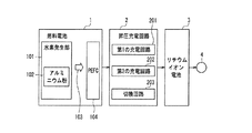
図1は、実施の形態1における燃料電池システムの構成を示すブロック図である。 FIG. 1 is a block diagram showing the configuration of the fuel cell system in the first embodiment.
図1において、燃料電池システムは、燃料電池1と昇圧充電回路2とリチウムイオン電池3と出力端子4とを備えている。燃料電池1は、水素発生部101と固体高分子型燃料電池104(以下、PEFCと称する。PEFC:Polymer Electrolyte Fuel Cell)とを備えている。昇圧充電回路2は、第1の充電回路201と第2の充電回路202と切換回路203とを備えている。
In FIG. 1, the fuel cell system includes a fuel cell 1, a
水素発生部101は、アルミニウム粉102に水を添加し加熱することにより、水素103を発生させている。発生された水素103は、PEFC104に供給されている。
The
PEFC104は、電解質とそれを挟む一対の電極(正極・負極)とで構成されたセルを、複数個備えてスタックを形成している。電解質には、固体高分子電解質が使われている。また、正極には正極活物質である空気中の酸素が供給され、負極には負極活物質である燃料(水素、メタノール)が供給されている。負極には、水素発生部101で発生した水素103が供給される。この構成において、負極活物質の水素イオンが電解質を通って正極側へ移動し、酸素分子と結合する時に、外部回路中を電子が移動し発電される。なお、PEFC104において使用される電解質、正極活物質、負極活物質の構成は、上記に限定されるものではない。
The PEFC 104 includes a plurality of cells each including an electrolyte and a pair of electrodes (a positive electrode and a negative electrode) sandwiching the electrolyte to form a stack. A solid polymer electrolyte is used as the electrolyte. Further, oxygen in the air that is a positive electrode active material is supplied to the positive electrode, and fuel (hydrogen, methanol) that is a negative electrode active material is supplied to the negative electrode.
第1の充電回路201は、リチウムイオン電池3の電圧が第1の充電電圧未満の場合に、リチウムイオン電池3の充電を行う回路である。具体的な充電制御は、PEFC104の出力電圧が第1の設定電圧となるようにPEFC104から電流を取り出す電流制御を行ない、それを昇圧し、充電電流としてリチウムイオン電池3に充電する。その際、第1の設定電圧は、燃料電池1の出力効率を高める電圧に設定されていることにより、効率化を図ることができる。
The
第2の充電回路202は、リチウムイオン電池3の電圧が第1の充電電圧に達した場合に切換回路203によって選択され、第1の充電電圧を維持するように昇圧充電回路2の出力電圧を制御し、リチウムイオン電池3の充電を行う回路である。その際、同時に、燃料電池1の出力電圧を監視し、出力電圧が第1の設定電圧以下とならないように昇圧動作を制限している。すなわち、リチウムイオン電池3の出力増加により昇圧充電回路2が燃料電池1の出力電流を増加させようとした場合でも、それを阻止することにより燃料電池1の出力電圧の低下を防止している。
The
切換回路203は、リチウムイオン電池3の両端端子電圧に基づき、第1の充電回路201と第2の充電回路202のうちいずれかを選択するよう切り替える回路である。本実施の形態では、リチウムイオン電池3の両端端子電圧が第1の充電電圧未満の時は第1の充電回路201を選択し、第1の充電電圧以上の時は第2の充電回路202を選択するように切り換えている。なお、切換回路203は、スイッチ素子の接点の接続/非接続で切り換える構成や、トランジスタやダイオードなどの半導体素子のオン/オフで切り換える構成などが考えられる。また、切換回路203は、リチウムイオン電池3の両端端子電圧と第1の充電電圧との比較に基づいて切り換えられている構成の他に、第1の充電電圧よりも低い第2の充電電圧を設定し、端子電圧が第1の充電電圧に到達した時は第2の充電回路202に切り換え、端子電圧が第2の充電電圧まで低下した時は第1の充電回路201に切り換えるように構成してもよい。
The
出力端子4は、負荷(携帯端末の電源回路など)が接続される端子であり、出力端子4に電源回路などを接続させることで、リチウムイオン電池3から電源回路へ給電が行われ、携帯端末を動作させることができる。
The output terminal 4 is a terminal to which a load (such as a power supply circuit of a portable terminal) is connected. By connecting a power supply circuit or the like to the output terminal 4, power is supplied from the
以下、動作を簡単に説明する。 The operation will be briefly described below.
燃料電池1において、水素発生部101でアルミニウム粉102と水とによって発生された水素103は、PEFC104へ供給され、PEFC104において発電される。PEFC104から出力される電圧は、昇圧充電回路2により昇圧され、リチウムイオン電池3に充電される。昇圧充電回路2は、リチウムイオン電池3を充電するにあたって、リチウムイオン電池3の両端で測定される電圧に基づき切換回路203が切り替えられて、第1の充電回路201または第2の充電回路202で充電が行われる。
In the fuel cell 1, the
なお、切換回路203は、予め設定されている第1の充電電圧と、リチウムイオン電池3の端子電圧とを比較し、第1の充電回路201と第2の充電回路202のうちいずれか一方を選択するよう切り替えられている。
Note that the
また、昇圧充電回路2において、リチウムイオン電池3の端子電圧が第1の充電電圧未満の場合は、第1の充電回路201が選択される。第1の充電回路201は、PEFC104の出力電圧が第1の設定電圧となるように、PEFC104から電流を取り出す電流制御を行ない、それを昇圧し、充電電流としてリチウムイオン電池3に充電する。
Further, in the
一方、リチウムイオン電池3の電圧が第1の充電電圧に達した場合は、第2の充電回路202が選択され、第1の充電電圧を維持するように昇圧充電回路2の出力電圧を制御し、リチウムイオン電池3の充電が行われる。その際、同時に、PEFC104の出力電圧を監視し、PEFC104の出力電圧が第1の設定電圧以下にならないように制御されている。すなわち、リチウムイオン電池3から出力端子4に出力される電力が増加し、昇圧充電回路2がPEFC104の出力電流を増加させようとした場合でも、第2の充電回路202によってそれが阻止されることにより、PEFC104の出力電圧の低下を防止している。つまり、リチウムイオン電池3の充電電圧が、第1の充電電圧と一致あるいは近似する電圧になるように、定電圧充電制御(CV充電)が行われている。
On the other hand, when the voltage of the
このように、昇圧充電回路2は、充電時にリチウムイオン電池3の端子電圧を測定し、第1の充電電圧未満の場合は第1の充電回路201で充電が行われ、第1の充電電圧以上の場合は第2の充電回路202によって充電が行われる。また、第1の充電回路201で充電中に、端子電圧が第1の充電電圧に到達した時は、第2の充電回路202に切り替えられる。
As described above, the boosting
次に、負荷接続時の動作を説明する。 Next, the operation at the time of load connection will be described.
負荷に給電を行う場合、まずリチウムイオン電池3から出力端子4を介して、負荷に電流が流れる。この時、燃料電池1の水素発生部101において、アルミニウム粉102からの水素発生の開始や停止に時間を要するため、リチウムイオン電池3の端子電圧は低下する。リチウムイオン電池3の端子電圧が第1の充電電圧未満に低下すると、切換回路203は第1の充電回路201を選択するよう切り換えられ、第1の充電回路201は燃料電池1の出力電流を制御してリチウムイオン電池3の充電が行われる。充電中にリチウムイオン電池3の端子電圧が第1の充電電圧に到達したら、切換回路203は第2の充電回路202を選択するよう切り換えられ、リチウムイオン電池3は第2の充電回路202によって定電圧充電(CV充電)が行われる。
When power is supplied to the load, first, a current flows from the
また、燃料電池1からの電力供給を停止させる際、水素発生部101における水素発生動作を停止させる必要があるが、水素発生部101の水素発生動作を停止させても、すぐにPEFC104への水素供給は停止されず、水素103の供給がしばらく継続される。したがって、PEFC104においては発電動作が継続され、昇圧充電回路2の動作によりリチウムイオン電池3の充電が進んでしまう。しかし、充電が進行し、リチウムイオン電池3が満充電状態近くになったとしても、切換回路203によって第1の充電回路201から第2の充電回路202に切り替えられることにより、定電圧充電によって充電電圧の上昇を抑えつつ、燃料電池1の出力電圧の低下を防止しながら充電が継続される。すなわち、充電動作による燃料電池1の出力電圧の過度の低下を防止しつつ、リチウムイオン電池3の過充電を防止している。
Further, when the power supply from the fuel cell 1 is stopped, it is necessary to stop the hydrogen generation operation in the
以上のような燃料電池システムによれば、燃料電池1において水素発生に時間を要する場合でも、負荷変動に対応した充電を行うことができる。また、効率的で、機器の保護を配慮した充電を行うことができる。 According to the fuel cell system as described above, even when it takes time to generate hydrogen in the fuel cell 1, it is possible to perform charging corresponding to load fluctuations. In addition, it is efficient and can be charged in consideration of device protection.
次に、昇圧充電回路2の具体構成について説明する。
Next, a specific configuration of the
昇圧充電回路2は、入力される直流電流を昇圧して出力する回路であり、DC−DCコンバータのような動作を行う回路である。まずは、一般的な昇圧型DC−DCコンバータの構成について説明する。
The step-up
図7は、昇圧形のDC−DCコンバータの回路図である。図7において、DC−DCコンバータ50には、電源51と負荷52とが接続されている。DC−DCコンバータ50は、PWM制御回路60と変換回路70と分圧抵抗53及び54とを備えている。PWM制御回路60は、基準電源61、誤差増幅器62、スイッチ制御回路63を備えている。変換回路70は、インダクタ71、ダイオード72、スイッチ73を備えている。
FIG. 7 is a circuit diagram of a step-up DC-DC converter. In FIG. 7, a
以下、動作を簡単に説明する。 The operation will be briefly described below.
図7において、スイッチ制御回路63はスイッチ73をオン/オフするよう切換制御する回路であり、スイッチ73がFET(電界効果トランジスタ)等で構成されている場合、通常、一定周期のパルスを出力し、そのデューティ比を誤差増幅回路62からの出力により変化させる回路である。本例では、誤差増幅回路62の出力が高くなった場合はオンの期間を長くし、より負荷に電力を供給する動作を行うように構成されている。
In FIG. 7, a
負荷52の両端電圧Voutを分圧抵抗53及び54により分圧した電圧V1と、基準電源61の電圧VR3とは、誤差増幅回路62に入力され、両電圧を比較しその誤差電圧が出力される。ここで、負荷52の電圧Voutが高く、分圧された電圧V1が基準電源61の電圧VR3よりも高い場合、誤差増幅回路62の出力が低下し、スイッチ制御回路63によるスイッチ73のオンの期間が短く(デューティ比が低く)なるよう制御される。これにより、負荷52への電力供給が低下し、出力電圧Voutを低下させるように制御が行なわれる。
The voltage V 1 obtained by dividing the voltage V out at both ends of the load 52 by the
なお、変換回路70では、スイッチ73がオンになっている期間、電源51からインダクタ71に電流が流れて、インダクタ71において磁界エネルギーを蓄えられる。スイッチ73がオフとなった場合、インダクタ71に蓄積された磁界エネルギーにより、インダクタ71が電流の流れを継続させるようにインダクタ71の両端電圧が増加するため、ダイオード72を通じて負荷52に電流が供給されるような動作が行なわれる。このような動作により、電源51から高い電圧を負荷52に供給することができる(DC−DCコンバータの基本動作)。
In the
このようなDC−DCコンバータを小型に実現するため、基準電源61、誤差増幅回路62、スイッチ制御回路63を含むPWM制御回路60を、IC化した部品が市販されている。例えば、リニアテクノロジー社のLS1919等があり、一般に「PWM制御IC」等の名称で流通している。
In order to realize such a DC-DC converter in a small size, a component in which the
なお、図7に示す回路構成において、ダイオード72(いわゆるフライホイールダイオード)の変わりに、FET等のスイッチを設け、スイッチ73との協調動作によりDC−DCコンバータを実現することもできる。このような構成を図8に示す。
In the circuit configuration shown in FIG. 7, a switch such as an FET can be provided instead of the diode 72 (so-called flywheel diode), and a DC-DC converter can be realized by a cooperative operation with the
図8において、図7の構成と異なるのは、スイッチ制御回路63に代えて端子50dが追加されたスイッチ制御回路64を設けた点と、ダイオード72に代えてスイッチ74を設けた点である。スイッチ74の切り換え動作は、スイッチ制御回路64から端子50d及び70dを介して入力される制御信号によって制御される。スイッチ制御回路64により、スイッチ73とスイッチ74とをオン/オフ切り換え制御することにより、DC−DC変換動作を行なわせることができる。このような構成は、いわゆる同期整流形DC−DCコンバータとして知られている。
8 differs from the configuration of FIG. 7 in that a
次に、第1の充電回路の構成について説明する。 Next, the configuration of the first charging circuit will be described.
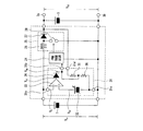
図2は、第1の充電回路の具体的な回路構成を示す回路図である。図2の構成は、燃料電池システムに第1の充電回路を搭載した場合の構成を示している。なお、第1の充電回路は、図2における第1の充電補助回路21とPWM制御回路24と変換回路25とで構成されている。
FIG. 2 is a circuit diagram showing a specific circuit configuration of the first charging circuit. The configuration of FIG. 2 shows a configuration when the first charging circuit is mounted on the fuel cell system. The first charging circuit includes the first
図2において、昇圧充電回路2は、燃料電池1とリチウムイオン電池3とに接続され、第1の充電補助回路21、PWM制御回路24、変換回路25を備えている。補助回路21は、基準電源22、誤差増幅回路23を備えている。変換回路25は、インダクタ26、ダイオード27、スイッチ28を備えている。なお、PWM制御回路24の具体構成は、図5のPWM制御回路60に示す構成と同等である。
In FIG. 2, the boosting
以下、動作について説明する。 The operation will be described below.
図2において、燃料電池1で発生した電圧VINに基づく電圧V1は、端子2a及び21aを介して誤差増幅回路23の反転入力端子に入力される。一方、基準電源22の基準電圧VR1は誤差増幅回路23の非反転入力端子に入力される。誤差増幅回路23は、入力される電圧V1と基準電圧VR1とを比較し、両電圧の誤差分を増幅して出力する。誤差増幅回路23の出力電圧は、端子21bを介してPWM制御回路24に入力される。
In FIG. 2, the voltage V 1 based on the voltage V IN generated in the fuel cell 1 is input to the inverting input terminal of the error amplifier circuit 23 via the
PWM制御回路24は、図7のPWM制御回路60に示すように構成されており、誤差増幅回路23から入力される電圧と基準電圧VR3とに基づき、所定のデューティ比を有するPWMパルスを出力する。PWM制御回路24から出力されるPWMパルスはスイッチ28に入力され、スイッチ28は一定の周期でオン/オフに切換え制御される。
The
なお、PWM制御回路24の出力パルスは、そのデューティ比が、誤差増幅回路23からの出力によって変化する。本例では、誤差増幅回路23の出力が高くなった場合(入力電圧V1が低い場合)は、スイッチ28のオン期間を長くし、リチウムイオン電池3に、より大きな電力を供給している。また、誤差増幅回路23の出力が低い場合(入力電圧V1が高い場合)は、スイッチ28のオン期間を短くし、リチウムイオン電池3に小さな電力を供給している。
Note that the duty ratio of the output pulse of the
PWM制御回路24において、端子21bを介して入力される電圧が上昇する場合、変換回路25の昇圧動作を低下(すなわち、スイッチ28のオン時間を縮小しダイオード27を通じて出力される電流を低下させる)させており、この動作を利用して第1の充電回路201(図1参照)を実現している。
In the
具体的な動作としては、燃料電池1の電圧V1が下降すると、誤差増幅回路23から端子21bを介してPWM制御回路24へ入力される電圧は上昇する。そのため、変換回路25におけるスイッチ28のスイッチング動作が低下するので、リチウムイオン電池3の充電電流、すなわち燃料電池1の出力電流が低下し、燃料電池1の電圧VIN及び電圧V1は上昇する。
As a specific operation, when the voltage V 1 of the fuel cell 1 decreases, the voltage input from the error amplifying circuit 23 to the
燃料電池1の出力電圧V1が下降した場合も同様であり、基準電源22の設定に応じて、燃料電池1が一定の出力電圧となるように電流制御される。このように制御されるため、基準電源22の出力電圧VR1の設定を、燃料電池1の運転効率が高くなるように設定すれば、燃料電池システムの効率化が図れる。
The same applies to the case where the output voltage V 1 of the fuel cell 1 is lowered, depending on the setting of the
以上のように構成された第1の充電回路により、燃料電池1の出力電圧を一定に保ちつつ、リチウムイオン電池3への充電を行うことができる。
With the first charging circuit configured as described above, it is possible to charge the
次に、第2の充電回路の構成について説明する。 Next, the configuration of the second charging circuit will be described.
図3は、第2の充電回路の具体的な回路構成を示す回路図である。図3の構成は、燃料電池システムに第2の充電回路を搭載した場合の構成を示している。なお、図3において、図2の構成と同様の構成要素については、同一番号を付与して説明は省略する。また、第2の充電回路は、第2の充電補助回路31とPWM制御回路24と変換回路25とで構成されている。
FIG. 3 is a circuit diagram showing a specific circuit configuration of the second charging circuit. The configuration of FIG. 3 shows a configuration when the second charging circuit is mounted on the fuel cell system. In FIG. 3, the same constituent elements as those in FIG. The second charging circuit includes a second
図3において、第2の充電補助回路31は、基準電源32、誤差増幅回路33、ダイオード34,分圧抵抗35及び36を備えている。さらに、変換回路25の出力電圧(すなわちリチウムイオン電池3の端子電圧)が入力される端子31dが配され、分圧抵抗35及び36に接続されている。
In FIG. 3, the second
以下、動作について説明する。 The operation will be described below.
図3において、燃料電池1の出力電圧VINが高い場合の動作について説明する。この場合、誤差増幅回路33の出力電圧は低下しているので、PWM制御回路24の入力に対してダイオード34は逆極性となり、燃料電池1の出力電圧の影響は受けない。一方、リチウムイオン電池3の電圧VCGは、分圧抵抗35及び36により分圧され、PWM制御回路24に入力される。従って、第2の充電補助回路31は、図7に基づいて説明したようなDC−DC変換動作を行うことになり、変換回路25からは一定の電圧がリチウムイオン電池3に出力され、定電圧充電が行われる。
In FIG. 3, the operation when the output voltage V IN of the fuel cell 1 is high will be described. In this case, since the output voltage of the
この場合に、分圧抵抗35及び36における分圧比の設定により、リチウムイオン電池3への充電電圧を、所望の電圧(第1の充電電圧)に設定することができる。よって、充電電圧をリチウムイオン電池3の充電の際に利用される終止電圧に設定しておくことにより、リチウムイオン電池3の過充電を防止することができる。
In this case, the charging voltage to the
図3に示す構成では、上記のようにリチウムイオン電池3に対して定電圧充電を継続するが、端子3a及び3bは外部に出力されて外部負荷に電力が供給されているので、外部負荷の状態によっては、リチウムイオン電池3が大きく放電する場合がある。このような場合、リチウムイオン電池3の両端の電圧VCGが低下する。電圧VCGが低下すると、分圧抵抗35及び36によって分圧される電圧が低下するため、PWM制御回路24の入力電圧が低下する。よって、PWM制御回路24は、デューティ比が高いPWMパルスをスイッチ28へ出力し、スイッチ回路28はオン期間が長いスイッチング動作が行われる。これにより、燃料電池1は、出力電流が増大し、出力電圧が低下することになる。
In the configuration shown in FIG. 3, constant voltage charging is continued for the
過度の電流増加による燃料電池1の出力電圧の低下は、燃料電池1の劣化を招くため、これを防止する必要がある。このような状態が生じた場合、先に図2を参照して説明したように、電圧V1が低下するため誤差増幅回路33の出力電圧が上昇し、ダイオード34を通じてPWM制御回路24へ入力される電圧が上昇する。そのため、変換回路25の変換動作が低下(PWM信号のデューティ比が低くなる)し、燃料電池1の出力電流が低下するので、燃料電池1の電圧VINの低下を防止できる。
A decrease in the output voltage of the fuel cell 1 due to an excessive increase in current leads to deterioration of the fuel cell 1, and thus must be prevented. When such a state occurs, as described above with reference to FIG. 2, the voltage V 1 decreases, so that the output voltage of the
このような動作により、第2の充電回路は、燃料電池1の出力電圧VINが第1の設定電圧に対して低下することを防止しつつ、リチウムイオン電池3の充電電圧VCGを第1の充電電圧に設定し、定電圧充電制御を継続できる。
By such an operation, the second charging circuit prevents the output voltage V IN of the fuel cell 1 from decreasing with respect to the first set voltage, and the charging voltage V CG of the
なお、外部負荷が大きくなった場合、燃料電池1の出力による充電電流と、リチウムイオン電池3の放電電流との総和により負荷電流が供給され、負荷が低下した場合はリチウムイオン電池3に充電が再開される。このような動作により、リチウムイオン電池3はバッファとしての動作を実現している
また、図面には示さなかったが、燃料電池1を動作させるため、例えばアルミニウム粉への水の供給、或いは、それを加熱する等の処置をする必要があり、そのためのポンプ等の機器、いわゆる補機を動作させる必要があるが、補機を動作させるための電源は、リチウムイオン電池3を利用することで、部品点数の削減などの効果がある。なお、補機へ給電するための構成や動作については、説明を省略する。
When the external load increases, the load current is supplied by the sum of the charging current from the output of the fuel cell 1 and the discharging current of the
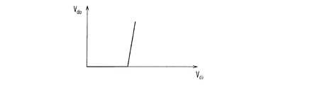
また、第2の充電補助回路31は図3に示す構成に限らず、図4に示すように構成してもよい。図4において、図3に示す第2の充電補助回路31の構成と異なる点は、増幅回路37を追加した点である。増幅回路37は、非反転入力端子に誤差増幅回路33の出力端子が接続され、反転入力端子にダイオード34の出力端子が接続されている。また、図5Aは図3におけるダイオード34の入力電圧VDiと出力電圧VDOとの関係を示す特性図で、図5Bは図4におけるダイオード34の入力電圧VDiと出力電圧VDOとの関係を示す特性図である。
Further, the second
図5Aに示すように、図3に示す第2の充電補助回路31の構成では、入力電圧VDiに対して出力電圧VDOが徐々に上昇する特性であるため、ダイオード34の導通開始時のダイオード特性や温度依存性により、出力電圧VDOが変動(図5Aの点線に示す特性)する可能性があり、燃料電池1の出力電圧低下を防止する設定電圧の精度等が低下してしまう。一方、第2の充電補助回路を図4に示すように構成すれば、増幅回路37において増幅された電圧に基づいてダイオード34が導通状態になるため、出力電圧VDOを急峻に立ち上げることができ、温度依存性が少ない出力電圧VDOを得ることができる。
As shown in FIG. 5A, the configuration of the second
以上、リチウムイオン電池3の充電制御を行う第1の充電回路、第2の充電回路の具体的な回路構成や動作について説明したが、次に、両充電回路を搭載した燃料電池システムの概要について説明する。
The specific circuit configurations and operations of the first charging circuit and the second charging circuit for controlling the charging of the
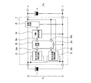
図6は、第1の充電回路及び第2の充電回路を備えた燃料電池システムの、要素的な内容を説明するためのブロック図である。なお、図6には各充電回路の明確な記述はないが、第1の充電補助回路21とPWM制御回路24と変換回路25とが動作してリチウムイオン電池3の充電を行う動作が、「第1の充電回路による充電動作」に相当する。また、第2の充電補助回路31とPWM制御回路24と変換回路25とが動作してリチウムイオン電池3の充電を行う動作が、「第2の充電回路による充電動作」に相当する。
FIG. 6 is a block diagram for explaining the elemental contents of the fuel cell system including the first charging circuit and the second charging circuit. Although there is no clear description of each charging circuit in FIG. 6, the operation of charging the
図6において、第1の充電補助回路21の具体構成は、図2に示した通りである。第2の充電補助回路31の具体構成は、図3または図4に示した通りである。PWM制御回路24の具体構成は、図5に示した通りである。変換回路25の具体構成は、図2または図3に示した通りである。
In FIG. 6, the specific configuration of the first
切換回路29は、前述したように、第1の充電回路及び第2の充電回路はPWM制御回路24を通じて制御されるように説明したが、これを利用して切り替えを簡便に実施するように構成している。また、切換回路29は、リチウムイオン電池3の両端の電圧VCGを監視し、電圧VCGが第1の充電電圧に達するまでは第1の充電補助回路21からの出力をPWM制御回路24に伝え、電圧が第1の充電電圧に達した後は第2の充電補助回路31からの出力をPWM制御回路24に伝えることにより、2つの充電回路を切り替えて動作させている。
As described above, the switching
なお、外部負荷によりリチウムイオン電池3が放電する場合を想定して、第2の充電回路で充電中にリチウムイオン電池3の電圧が低下しても、一定のヒステリシスを持たせるように、第2の充電電圧に低下するまでは第2の充電回路による充電を継続する構成にしておいてもよい。
Assuming that the
以下、このような切替回路29の一実施例を、図9を参照して動作を説明する。
The operation of one embodiment of such a
図9に於いて、端子29aから29eまでの端子は、図6の切替回路29に示されている端子であり、切替回路の内部回路の接続状態を説明するために図示している。図9の切替回路29は、スイッチ90、基準電源91、コンパレータ92を備えている。なお、スイッチ90は説明の都合上、制御電圧が高い(Hi)の場合、端子29a側を選択するものとする。
In FIG. 9,
このような回路構成では、端子29aから入力される第1の充電補助回路21の信号がスイッチ90により選択されて端子29eを通じてPWM制御回路24に接続される場合には、先に述べたように「第1の充電回路による充電動作」が行われる。一方、スイッチ90により端子29bの信号が選択されて端子29eに出力される場合は「第2の充電回路による充電動作」が行われる。従って、基準電源91を第1の充電電圧に設定しておけば、端子29dの電圧が基準電源91より低い場合、すなわち、リチウムイオン電池3の電圧が第1の充電電圧より低い場合、コンパレータ92の出力はHiとなり、スイッチ90は端子29aを選択するので、「第1の充電回路による充電動作」が行われることになる。
In such a circuit configuration, when the signal of the first
充電が進行し、リチウムイオン電池3の電圧が第1の充電電圧より上昇した場合、コンパレータ92の出力が反転するのでスイッチ90は端子29bを選択し、「第2の充電回路による充電動作」が行われる。
When charging proceeds and the voltage of the
このように、切替回路29により充電動作の切替えを行うが、このような回路構成ではコンパレータ92の入力にノイズ等が混入される場合、切替えの動作が頻発に発生する問題が生じることがある。そこで、切替に際して、先に説明したように一定のヒステリシスを持たせてもよく、これを実現する為の一実施例を図10に示し、以下説明する。
In this way, the switching operation is switched by the switching
図10は、図9のコンパレータに抵抗93及び抵抗94を追加してヒステリシスを持たせ、更に、ヒステリシスの電圧を設定しやすくするためにダイオード95を追加した構成である。
FIG. 10 shows a configuration in which a
図10において、端子29dの電圧が十分に低い場合、コンパレータ92の出力はHiとなるが、この場合、ダイオード95は非導通方向に電圧が印加されるので、抵抗93には電流が流れず、基準電源91の電圧がそのままコンパレータ92に入力される。従って、基準電源91の電圧にリチウムイオン電池3の電圧が到達するまで、スイッチ90は端子29を選択するので、「第1の充電回路による充電動作」により充電が行われる。
In FIG. 10, when the voltage at the terminal 29d is sufficiently low, the output of the
充電が進行するにつれて端子29dのリチウムイオン電池3の電圧が上昇するが、端子29dの電圧が基準電源91を超えた場合、コンパレータ92が反転しLowとなる。この場合、スイッチ90が端子29bを選択するので、充電動作としては「第2の充電回路による充電動作」が行われる。このとき、同時にダイオード95が導通状態になるので、抵抗93を通じて抵抗94に基準電源91から電流が流出する方向に電流が流れ、基準電源91の出力電圧から抵抗94による電圧降下の分だけ低下した電圧がコンパレータ92に印加される。従って、第1の充電電圧より低い電圧まで端子29dの電圧が低下しないとコンパレータ92の出力が再度反転し、Hiとならない。
As charging progresses, the voltage of the
このように、ヒステリシス動作を持たせることができるが、そのヒステリシスの幅は抵抗93や抵抗94を調整することにより設定できる。本実施の形態の特徴は、第2の充電回路に切替える際に、基準電源91の電圧がそのまま第1の充電電圧となるようにヒステリシスを持たせるように構成したことである。しかし、これ以外にも回路構成方法があることは言うまでもなく、IC化に際してはコンパレータ92のトランジスタのゲート幅を変える等の方法により、回路を構成するに必要な素子数を低減することも可能であるが、当業者にとってはよく知られていることなので詳細は省略する。
Thus, a hysteresis operation can be provided, but the width of the hysteresis can be set by adjusting the
更に、満充電の判定には、満充電電流として一定電流以下のスレッショルド、例えば第1の満充電電流を設定し、それ以下に充電電流が低下した場合には充電動作を停止させるように制御してもよいことは言うまでもないが、これについても詳細説明は省略する。 Furthermore, in the determination of full charge, a threshold of a certain current or less, for example, a first full charge current, is set as the full charge current, and control is performed to stop the charging operation when the charge current falls below that. Needless to say, a detailed description thereof will be omitted.
以上のように本実施の形態によれば、リチウムイオン電池3が第1の充電電圧に達するまでは燃料電池1の出力電圧が第1の設定電圧となるように燃料電池1の出力電流を制御する第1の充電回路と、リチウムイオン電池3が第1の充電電圧に到達した後に燃料電池1の出力が第1の設定電圧以下へ低下することを防止するよう定電圧充電を行う第2の充電回路とを備え、それぞれの充電回路を選択的に切り換えてリチウムイオン電池3の充電を行う構成としたことにより、燃料電池運転の効率化を図ることができる。また、燃料電池1を保護しつつ、昇圧充電回路2によりリチウムイオン電池3を満充電まで充電させることができる。
As described above, according to the present embodiment, the output current of the fuel cell 1 is controlled so that the output voltage of the fuel cell 1 becomes the first set voltage until the
また、先の説明では詳細を省いたが、図3に示す構成や、図3に示す構成の一部を図4に示す構成に置き換えた構成だけでも、本発明が目的とする燃料電池の出力の低下を防ぎつつリチウムイオン電池が満充電付近となった場合にCV充電を行うような制御を実現することが可能であるので、回路構成を簡素化できコストダウンすることができる。 Further, although details are omitted in the above description, the output of the fuel cell intended by the present invention can be achieved only by the configuration shown in FIG. 3 or a configuration in which a part of the configuration shown in FIG. 3 is replaced with the configuration shown in FIG. Therefore, it is possible to realize control such that CV charging is performed when the lithium ion battery is nearly fully charged while preventing a decrease in battery voltage, so that the circuit configuration can be simplified and the cost can be reduced.
以下、先ずは図3に示す構成による動作を説明し、次に図3に示す構成に図4に示す構成を組み込んだ場合の動作を説明することにより、特に図9や図10に示した切替回路を使用せずとも本願発明の当初の目的を達することができることを示す。 In the following, the operation of the configuration shown in FIG. 3 will be described first, and then the operation when the configuration shown in FIG. 4 is incorporated in the configuration shown in FIG. It shows that the original object of the present invention can be achieved without using a circuit.
本発明では、先ずは第1の充電回路により燃料電池1の出力電圧を一定に保ちつつリチウムイオン電池3を充電し、その後、充電が進んでくると第2の充電回路によりリチウムイオン電池3の充電電圧を一定に保ちつつ充電する。
In the present invention, first, the
充電回路の構成例として、先に説明したように、通常のDC−DCコンバータと同様にPWM制御回路やインダクタ等を使用し、燃料電池1の出力を昇圧してリチウムイオン電池3に充電しているが、実際に充電回路を作成する場合は、市販のPWM制御を行なうICを利用することが多いと考えられる。そこで、図2では第1の充電回路の例として、PWM制御回路の入力側に極性を反転させて増幅する誤差増幅回路23を挿入する構成としている。
As a configuration example of the charging circuit, as described above, a PWM control circuit, an inductor, or the like is used similarly to a normal DC-DC converter, and the output of the fuel cell 1 is boosted to charge the
このように接続することにより、燃料電池1の電圧が低下するとPWM制御回路24の入力電圧を上昇させることにより昇圧動作を抑圧し、燃料電池1からの出力電流を低下させる。一方、燃料電池の電圧が上昇すると、PWM制御回路24の入力電圧を低下させて昇圧動作を亢進し、燃料電池1からの出力電流が増大されるので、燃料電池1の出力電圧を一定に保つような閉ループ制御が実現できる。
By connecting in this way, when the voltage of the fuel cell 1 decreases, the input voltage of the
なお、詳細な説明は省くが、このような誤差増幅回路やPWM制御用のICを用いて充電回路を構築した場合に、閉ループ制御としては、PWM制御用IC自体の設定の他に、誤差増幅回路23のゲインや位相の設定等により、より更に細かく設定できるので、安定な充電制御動作を実現できる特徴がある。 Although a detailed description is omitted, when a charging circuit is constructed using such an error amplification circuit or an IC for PWM control, in addition to setting the PWM control IC itself, closed loop control includes error amplification. Since it can be set more finely by setting the gain and phase of the circuit 23, there is a feature that a stable charge control operation can be realized.
一方、図3に示した第2の充電回路の実施形態は、基本的には通常のDC−DCコンバータ制御であり、出力電圧を一定に保つ閉ループ制御を行なっている。 On the other hand, the embodiment of the second charging circuit shown in FIG. 3 is basically a normal DC-DC converter control, and performs a closed loop control for keeping the output voltage constant.
本構成では、このような閉ループ制御の途中に、誤差増幅回路33の出力を、ダイオード34を通じてPWM制御回路24の入力端子31aに接続している。入力端子31aの電圧が基準電源32より低下した場合、ダイオード34を通じてPWM制御回路24の入力電圧を吊り上げる。このような状態は、DC−DCコンバータの出力電圧が上昇し過ぎた状態と同じであり、電圧変換動作を抑圧し、充電電流を低下させるように動作する。以上のように、燃料電池1の出力電圧低下防止制御が行なわれる。
In this configuration, the output of the
リチウムイオン電池3に充電を行なう場合、先ず第1の充電回路201により充電が行なわれ、充電終止電圧に到達した以降は第2の充電回路202により充電されるが、リチウムイオン電池3のみを充電すると想定した場合、第1の充電回路201により先ずは充電されているので、第2の充電回路202による充電電流は第1の充電回路201による充電電流に比べて減少している。従って、第2の充電回路202による充電に際しては、第1の充電回路201による充電に比べて、燃料電池1の出力電流は低下し、出力電圧は上昇する。このような場合、誤差増幅回路33等を利用した燃料電池1の出力電圧低下防止制御は動作しない。
When charging the
ただし、第2の充電回路202で充電中でも燃料電池システムとしては負荷を繋いでいるため、負荷が重くなった場合、出力電流が増大しリチウムイオン電池3の電圧が低下することがある。そのため、DC−DCコンバータ動作としては燃料電池1から電力を引き出して、充電動作を継続する。
However, since the load is connected as the fuel cell system even during charging by the
そのため、負荷の状態によっては、燃料電池1の出力電流の増大し、出力電圧が大幅に低下する恐れがある。そこで、誤差増幅回路33等により構成した電圧低下を防止する手段を用いて燃料電池1の出力電圧の低下を防止する。
Therefore, depending on the state of the load, the output current of the fuel cell 1 may increase, and the output voltage may be greatly reduced. Therefore, a decrease in the output voltage of the fuel cell 1 is prevented by using a means for preventing a decrease in voltage constituted by the
このような特徴を持つ第1の充電回路201と第2の充電回路202とを切替えることにより、燃料電池1やリチウムイオン電池3の保護を行ないつつ安定に充電動作を継続させている。
By switching between the
しかし、誤差増幅回路33等により構成した電圧低下を防止する回路を積極的に利用すると、図3や、図3の一部に図4を適用した回路構成、即ち、第2の充電回路202だけで燃料電池1の出力電圧を一定に保ちつつ、リチウムイオン電池3が終止電圧に達した場合にCV充電を行なわせる動作が可能となる。
However, if the circuit configured to prevent the voltage drop configured by the
これは、第2の充電回路202の一実施例として示した図3に示す構成では、DC−DCコンバータの出力電圧を終止電圧となるように設定しているが、このような設定の場合、リチウムイオン電池3の電圧が低下すると、可能な限りDC−DCコンバータの動作を亢進し、コンバータ出力電圧を上昇させるように閉ループ制御が働く。そのため、閉ループ制御により、DC−DCコンバータの入力電流を可能な限り増大させ、燃料電池1の出力電圧が急激に低下するように動作する。
In the configuration shown in FIG. 3 shown as an example of the
しかし、誤差増幅回路33等によって構成された、燃料電池1の電圧低下防止手段が働くことにより、PWM制御回路へ入力されるDC−DCコンバータ出力電圧の低下を防止し、DC−DCコンバータの変換動作が抑圧されるので、燃料電池1の出力電圧が基準電源32で設定された電圧より低下することはない。
However, the voltage drop prevention means of the fuel cell 1 constituted by the
従って、充電動作としては、燃料電池1の動作状態は、燃料電池1の出力電圧低下防止制御で決まる出力電圧と水素供給量から決まる出力電流により決まり、更に、リチウムイオン電池3の充電電流は、燃料電池1の出力電圧と電流、及びリチウムイオン電池3の電池電圧とから決まる。
Therefore, as the charging operation, the operating state of the fuel cell 1 is determined by the output voltage determined by the output voltage drop prevention control of the fuel cell 1 and the output current determined by the hydrogen supply amount, and the charging current of the
また、さらに充電が亢進し、リチウムイオン電池3の電池電圧がDC−DCコンバータとして設定した充電終止電圧に達すると、端子31bに印加され分圧されたリチウムイオン電池3の電圧が、PWM制御回路24によるDC−DCコンバーター動作を停止する電圧付近となるので、充電動作が抑圧され、充電電流が減少する。それに伴い、燃料電池1からの出力電流が低下するので、燃料電池1の出力電圧が上昇し、誤差増幅回路33の出力電圧は低下する。このため、ダイオード34が逆極性となってカットオフするので、誤差増幅回路33等により構成された燃料電池1の電圧低下防止手段が動作することはなくなり、分圧抵抗35等で構成されるDC−DCコンバーターの閉ループ制御による定電圧充電制御のみ(即ち、第1の充電手段のみ)が動作するようになる。
Further, when the charging is further promoted and the battery voltage of the
なお、燃料電池システムの負荷が増大しリチウムイオン電池3の電圧が低下した場合は、最初の制御動作に戻って、DC−DCコンバータ制御と電圧低下防止制御とが平衡する状態で充電が継続する。
In addition, when the load of the fuel cell system increases and the voltage of the
以上のように、特に切替回路を利用することなく当初の充電動作を行なうことが、図3に示す回路構成だけによって実現できるので、回路構成を簡素化でき、コストダウンすることができる。 As described above, since it is possible to realize the initial charging operation without particularly using the switching circuit only by the circuit configuration shown in FIG. 3, the circuit configuration can be simplified and the cost can be reduced.
なお、先に図4の実施形態について、温度特性の向上等が実現できる旨を説明したが、図4の構成を図3に組み込んだ構成でも、第1及び第2の充電動作が可能である。これにより、精度向上を図りつつ、回路の簡素化とコストダウンが達成できる。以下、詳細に説明する。 In the embodiment of FIG. 4, it has been explained that the temperature characteristics can be improved. However, the first and second charging operations can be performed even when the configuration of FIG. 4 is incorporated in FIG. 3. . Thereby, simplification of the circuit and cost reduction can be achieved while improving accuracy. Details will be described below.
図3の例では、DC−DCコンバータとしての制御において、リチウムイオン電池3をCV充電する際の終止電圧は、同様な材質で構成される抵抗35や抵抗36により分圧されて決まるので、CV充電での充電電圧自体の誤差は生じにくい。しかし、先に図4の説明において示したように、燃料電池1の出力電圧が一定電圧以下に低下しないように制御している最中には、ダイオードの両端電圧が燃料電池1の出力電圧の低下を防止する設定電圧の一部として含まれ、燃料電池1の出力電圧低下を防止する設定電圧の精度等が低下してしまう。
In the example of FIG. 3, in the control as the DC-DC converter, the end voltage when the
通常、PWM制御回路24の入力インピーダンスは大きいので、ダイオード34の負荷は抵抗35、抵抗36となり、その負荷を通じてダイオード34中に電流が流れる。その際、誤差増幅回路33のゲイン設定や抵抗値の設定によっては、図5Aで示したように、ダイオード34の電流電圧特性、特に温度特性によって、ダイオード34の両端の電位差が変化するので、燃料電池1の出力電圧が変化する恐れがある。
Usually, since the input impedance of the
そこで、図4に示したようにダイオード34を増幅回路37のループ内に入れることにより、ダイオード動作をオンオフ動作とさせ、ダイオードの温度特性等を解消する。
Therefore, by putting the
今、抵抗により分圧された出力であるVdiの電位よりも、端子31aを誤差増幅回路33で反転増幅したVdoの電位の方が低い場合、これは、燃料電池1の出力電圧が高い場合に相当するが、このような場合、増幅回路37の出力電圧は低下するのでダイオード34は逆極性となり、ダイオード34はオフとなる。従って、誤差増幅回路33の出力の影響は端子31bには全く表れなくなる。
If the potential of V do obtained by inverting and amplifying the terminal 31a with the
これに対し、Vdiの電位よりVdoの電位の方が高い場合、これは、燃料電池1の出力電圧が低下した場合に相当するが、増幅回路37の−端子より+端子のほうが低電圧となる。この場合、増幅回路37の出力は上昇するのでダイオード34に印加される電圧は順方向の極性となり、ダイオード34はオンとなり導通する。このため、増幅回路37の出力によりVdoの電位を上昇させようとする。しかし、Vdoは−端子に接続されているので、反転増幅され、Vdoの電位を逆に下降させようとするフィードバック制御となる。そのため、Vdoを上昇させ、できるだけVdiに近づける制御を行い、Vdiの出力が端子31bに表れることになり、誤差増幅回路33が端子31bに接続されることになる。
On the other hand, when the potential of V do is higher than the potential of V di , this corresponds to a case where the output voltage of the fuel cell 1 is lowered, but the voltage at the + terminal is lower than the − terminal of the
従って、この場合、誤差増幅回路33の出力によりPWM制御回路24が動作することになり、第1の制御回路と同様の動作となる。
Therefore, in this case, the
また、ダイオード34はオンオフ動作となるので、誤差は増幅回路37のオフセット電圧等の誤差となるが、通常、これらのオフセット電圧の誤差や温度特性は良好である。従って、ダイオード34の有する温度特性が表れ難く、燃料電池1の出力電圧の誤差が殆ど生じなくなる。
Since the
以上、当業者にとっては良く知られたダイオード接続等の動作について説明したが、このような回路構成を燃料電池システムに組み入れることにより、燃料電池1の出力電圧設定誤差が少なく、また、リチウムイオン電池3の充電電圧精度の維持やそれに伴うリチウムイオン電池3の保護動作が実現できるので、燃料電池システムとしてコストダウンを図った好適な充電手段を構築できる。
As described above, operations such as diode connection, which are well known to those skilled in the art, have been described. By incorporating such a circuit configuration in the fuel cell system, the output voltage setting error of the fuel cell 1 is small, and the
なお、本実施の形態では、燃料電池1における発電の燃料は水素であるが、他の燃料であってもよい。また、本実施の形態では、燃料電池1で発生された電力をリチウムイオン電池3に充電させているが、充電させる二次電池はこれに限らない。
In the present embodiment, the fuel for power generation in the fuel cell 1 is hydrogen, but other fuels may be used. Moreover, in this Embodiment, although the electric power generated with the fuel cell 1 is charged to the
本発明は、小型携帯機器用の燃料電池システムに有用である。 The present invention is useful for a fuel cell system for small portable devices.
1 燃料電池
101 水素発生部
102 アルミニウム粉
103 水素
104 PEFC
2 充電昇圧回路
201 第1の充電回路
202 第2の充電回路
203 切換回路
3 リチウムイオン電池
4 出力端子
DESCRIPTION OF SYMBOLS 1
2 charging
Claims (7)
充電可能な二次電池と、
前記燃料電池で発生された電力を、昇圧して前記二次電池に充電させる昇圧充電回路とを備えた燃料電池システムであって、
前記昇圧充電回路は、
前記二次電池の端子電圧が第1の充電電圧未満の場合、前記燃料電池の出力電圧が第1の設定電圧となるように前記燃料電池の出力電流の制御を行なう第1の充電回路と、
前記二次電池の端子電圧が第1の充電電圧以上の場合、前記燃料電池の出力電圧が第1の設定電圧以下へ低下することを防止するよう電流制御するとともに、前記二次電池への充電電圧を第1の充電電圧に保持する定電圧充電制御を行なう第2の充電回路とを備え、
前記第1の充電回路と前記第2の充電回路のうちいずれか一方を選択して、前記二次電池の充電を行うことを特徴とする燃料電池システム。 A fuel cell capable of generating electricity by chemically reacting fuel;
Rechargeable secondary battery,
A fuel cell system comprising a boosting charging circuit that boosts the electric power generated in the fuel cell to charge the secondary battery;
The step-up charging circuit includes:
A first charging circuit that controls the output current of the fuel cell so that the output voltage of the fuel cell becomes a first set voltage when the terminal voltage of the secondary battery is less than a first charging voltage;
When the terminal voltage of the secondary battery is equal to or higher than the first charging voltage, current control is performed to prevent the output voltage of the fuel cell from dropping below the first set voltage, and charging to the secondary battery is performed. A second charging circuit for performing constant voltage charging control for holding the voltage at the first charging voltage;
A fuel cell system, wherein one of the first charging circuit and the second charging circuit is selected to charge the secondary battery.
基準電圧源と、
前記基準電圧源の出力電圧と前記燃料電池の端子電圧とを比較し、その誤差電圧が出力される誤差増幅回路と、
前記誤差増幅回路から出力される誤差電圧によってデューティ比が可変されたパルスが出力されるPWM制御回路と、
前記PWM制御回路から出力されるパルスによってオンまたはオフに切り換えられ、前記二次電池の充電電流を増減させるスイッチとを備えた請求項1記載の燃料電池システム。 The first charging circuit includes:
A reference voltage source;
An error amplifying circuit that compares the output voltage of the reference voltage source and the terminal voltage of the fuel cell and outputs the error voltage;
A PWM control circuit that outputs a pulse with a duty ratio varied by an error voltage output from the error amplification circuit;
The fuel cell system according to claim 1, further comprising a switch that is switched on or off by a pulse output from the PWM control circuit and increases or decreases a charging current of the secondary battery.
基準電圧源と、
前記基準電圧源の出力電圧と前記燃料電池の端子電圧とを比較し、その誤差電圧が出力される誤差増幅回路と、
前記誤差増幅回路から出力される誤差電圧によって、オンまたはオフに切り換えられるダイオードと、
前記二次電池の端子電圧を分圧する分圧抵抗と、
前記ダイオードの出力電圧、または前記分圧抵抗で分圧された電圧によって、デューティ比が可変されたパルスが出力されるPWM制御回路と、
前記PWM制御回路から出力されるパルスによってオンまたはオフに切り換えられ、前記二次電池の充電電流を増減させるスイッチとを備えた請求項1記載の燃料電池システム。 The second charging circuit includes:
A reference voltage source;
An error amplifying circuit that compares the output voltage of the reference voltage source and the terminal voltage of the fuel cell and outputs the error voltage;
A diode switched on or off by an error voltage output from the error amplifier circuit;
A voltage dividing resistor for dividing the terminal voltage of the secondary battery;
A PWM control circuit that outputs a pulse with a duty ratio varied by an output voltage of the diode or a voltage divided by the voltage dividing resistor;
The fuel cell system according to claim 1, further comprising a switch that is switched on or off by a pulse output from the PWM control circuit and increases or decreases a charging current of the secondary battery.
充電可能な二次電池と、
前記燃料電池で発生された電力を、昇圧して前記二次電池に充電させる昇圧充電回路とを備えた燃料電池システムであって、
前記昇圧充電回路は、
基準電圧源と、
前記基準電圧源の出力電圧と前記燃料電池の端子電圧とを比較し、その誤差電圧が出力される誤差増幅回路と、
前記誤差増幅回路から出力される誤差電圧によって、オンまたはオフに切り換えられるダイオード特性を持ったダイオード回路と、
前記二次電池の端子電圧を分圧する分圧抵抗と、
前記ダイオード回路の出力電圧を、または前記分圧抵抗で分圧された電圧によってデューティ比が可変されたパルスが出力されるPWM制御回路と、
前記PWM制御回路から出力されるパルスによってオンまたはオフに切り換えられ、前記二次電池の充電電流を増減させるスイッチとを備えたことを特徴とする燃料電池システム。 A fuel cell capable of generating electricity by chemically reacting fuel;
Rechargeable secondary battery,
A fuel cell system comprising a boosting charging circuit that boosts the electric power generated in the fuel cell to charge the secondary battery;
The step-up charging circuit includes:
A reference voltage source;
An error amplifying circuit that compares the output voltage of the reference voltage source and the terminal voltage of the fuel cell and outputs the error voltage;
A diode circuit having a diode characteristic that is switched on or off by an error voltage output from the error amplifier circuit;
A voltage dividing resistor for dividing the terminal voltage of the secondary battery;
A PWM control circuit that outputs a pulse having a duty ratio varied by an output voltage of the diode circuit or a voltage divided by the voltage dividing resistor;
A fuel cell system comprising: a switch that is switched on or off by a pulse output from the PWM control circuit and increases or decreases a charging current of the secondary battery.
Priority Applications (1)
| Application Number | Priority Date | Filing Date | Title |
|---|---|---|---|
| JP2006123789A JP2007299532A (en) | 2006-04-27 | 2006-04-27 | Fuel cell system |
Applications Claiming Priority (1)
| Application Number | Priority Date | Filing Date | Title |
|---|---|---|---|
| JP2006123789A JP2007299532A (en) | 2006-04-27 | 2006-04-27 | Fuel cell system |
Publications (1)
| Publication Number | Publication Date |
|---|---|
| JP2007299532A true JP2007299532A (en) | 2007-11-15 |
Family
ID=38768867
Family Applications (1)
| Application Number | Title | Priority Date | Filing Date |
|---|---|---|---|
| JP2006123789A Withdrawn JP2007299532A (en) | 2006-04-27 | 2006-04-27 | Fuel cell system |
Country Status (1)
| Country | Link |
|---|---|
| JP (1) | JP2007299532A (en) |
Cited By (3)
| Publication number | Priority date | Publication date | Assignee | Title |
|---|---|---|---|---|
| JP2011065832A (en) * | 2009-09-16 | 2011-03-31 | Hitachi Maxell Ltd | Fuel cell system and its power generation control method |
| JP2013027095A (en) * | 2011-07-19 | 2013-02-04 | Fuji Electric Co Ltd | Initial charger for electric power conversion system |
| CN110386005A (en) * | 2018-04-19 | 2019-10-29 | 奥迪股份公司 | Electrical energy system with fuel cell |
-
2006
- 2006-04-27 JP JP2006123789A patent/JP2007299532A/en not_active Withdrawn
Cited By (3)
| Publication number | Priority date | Publication date | Assignee | Title |
|---|---|---|---|---|
| JP2011065832A (en) * | 2009-09-16 | 2011-03-31 | Hitachi Maxell Ltd | Fuel cell system and its power generation control method |
| JP2013027095A (en) * | 2011-07-19 | 2013-02-04 | Fuji Electric Co Ltd | Initial charger for electric power conversion system |
| CN110386005A (en) * | 2018-04-19 | 2019-10-29 | 奥迪股份公司 | Electrical energy system with fuel cell |
Similar Documents
| Publication | Publication Date | Title |
|---|---|---|
| US7932634B2 (en) | Fuel cell hybrid power supply | |
| US20120013196A1 (en) | Fuel cell system and power managing method of the same | |
| CN1893216B (en) | Electronic equipment and battery components and load devices used in the electronic equipment | |
| US9496752B2 (en) | Hybrid power source system | |
| US7994765B2 (en) | Power supply device | |
| US20060222916A1 (en) | Mehotd for determining a maximum power point voltage of a fuel cell, as well as fuel cell control system and power controller used in the fuel cell control system | |
| US7750597B2 (en) | Power supply apparatus | |
| JP2009232665A (en) | Power supply device and power supply control method | |
| EP1528654A1 (en) | Circuit for battery/capacitor power source | |
| JP2007095617A (en) | Fuel cell device and control method thereof | |
| JP4115501B2 (en) | Charger, DC-DC converter provided with the charger, and control circuit thereof | |
| JP4753753B2 (en) | Fuel cell system | |
| JP2005346984A (en) | ELECTRONIC DEVICE SYSTEM, FUEL CELL UNIT, AND POWER SUPPLY CONTROL METHOD | |
| CN100511793C (en) | Power system for fuel cell, electronic equipment and electric power feeding method | |
| JPWO2006061894A1 (en) | Power supply | |
| JP5131805B2 (en) | Fuel cell system | |
| JP2006049175A (en) | Fuel cell system | |
| JP4564940B2 (en) | Electronic device and battery pack and load device used in the electronic device | |
| JP5336791B2 (en) | Power supply | |
| JP2007280741A (en) | Fuel cell device | |
| JP2007299532A (en) | Fuel cell system | |
| JP2008004379A (en) | Fuel cell system | |
| JP2006114486A (en) | Fuel cell power supply system | |
| JP2007244179A (en) | Hybrid power supply | |
| JP2011211812A (en) | Power unit |
Legal Events
| Date | Code | Title | Description |
|---|---|---|---|
| A621 | Written request for application examination |
Free format text: JAPANESE INTERMEDIATE CODE: A621 Effective date: 20090219 |
|
| A711 | Notification of change in applicant |
Free format text: JAPANESE INTERMEDIATE CODE: A712 Effective date: 20110519 |
|
| RD02 | Notification of acceptance of power of attorney |
Free format text: JAPANESE INTERMEDIATE CODE: A7422 Effective date: 20110527 |
|
| A977 | Report on retrieval |
Free format text: JAPANESE INTERMEDIATE CODE: A971007 Effective date: 20110707 |
|
| A761 | Written withdrawal of application |
Free format text: JAPANESE INTERMEDIATE CODE: A761 Effective date: 20110721 |