JP2007299563A - High power sterilizer lamp - Google Patents
High power sterilizer lamp Download PDFInfo
- Publication number
- JP2007299563A JP2007299563A JP2006124943A JP2006124943A JP2007299563A JP 2007299563 A JP2007299563 A JP 2007299563A JP 2006124943 A JP2006124943 A JP 2006124943A JP 2006124943 A JP2006124943 A JP 2006124943A JP 2007299563 A JP2007299563 A JP 2007299563A
- Authority
- JP
- Japan
- Prior art keywords
- amalgam
- mercury
- bulb
- lamp
- tube
- Prior art date
- Legal status (The legal status is an assumption and is not a legal conclusion. Google has not performed a legal analysis and makes no representation as to the accuracy of the status listed.)
- Pending
Links
- 229910000497 Amalgam Inorganic materials 0.000 claims abstract description 115
- QSHDDOUJBYECFT-UHFFFAOYSA-N mercury Chemical compound [Hg] QSHDDOUJBYECFT-UHFFFAOYSA-N 0.000 claims abstract description 88
- 229910052753 mercury Inorganic materials 0.000 claims abstract description 60
- 239000010453 quartz Substances 0.000 claims abstract description 42
- VYPSYNLAJGMNEJ-UHFFFAOYSA-N silicon dioxide Inorganic materials O=[Si]=O VYPSYNLAJGMNEJ-UHFFFAOYSA-N 0.000 claims abstract description 42
- 229910052751 metal Inorganic materials 0.000 claims description 30
- 239000002184 metal Substances 0.000 claims description 30
- 230000001954 sterilising effect Effects 0.000 claims description 21
- 230000002093 peripheral effect Effects 0.000 claims description 13
- 238000004659 sterilization and disinfection Methods 0.000 claims description 10
- WABPQHHGFIMREM-UHFFFAOYSA-N lead(0) Chemical compound [Pb] WABPQHHGFIMREM-UHFFFAOYSA-N 0.000 claims description 6
- 230000002070 germicidal effect Effects 0.000 claims description 4
- APFVFJFRJDLVQX-UHFFFAOYSA-N indium atom Chemical group [In] APFVFJFRJDLVQX-UHFFFAOYSA-N 0.000 abstract description 37
- 230000006866 deterioration Effects 0.000 abstract 1
- XLYOFNOQVPJJNP-UHFFFAOYSA-N water Substances O XLYOFNOQVPJJNP-UHFFFAOYSA-N 0.000 description 25
- 230000007423 decrease Effects 0.000 description 16
- 239000007789 gas Substances 0.000 description 10
- 230000000052 comparative effect Effects 0.000 description 8
- 230000003247 decreasing effect Effects 0.000 description 7
- PXHVJJICTQNCMI-UHFFFAOYSA-N Nickel Chemical group [Ni] PXHVJJICTQNCMI-UHFFFAOYSA-N 0.000 description 6
- 229910052738 indium Inorganic materials 0.000 description 6
- 230000005855 radiation Effects 0.000 description 6
- 238000010586 diagram Methods 0.000 description 5
- 238000000034 method Methods 0.000 description 4
- 238000002474 experimental method Methods 0.000 description 3
- 230000000694 effects Effects 0.000 description 2
- 238000005286 illumination Methods 0.000 description 2
- 239000007791 liquid phase Substances 0.000 description 2
- 238000005259 measurement Methods 0.000 description 2
- 229910000645 Hg alloy Inorganic materials 0.000 description 1
- 229910000846 In alloy Inorganic materials 0.000 description 1
- ATJFFYVFTNAWJD-UHFFFAOYSA-N Tin Chemical compound [Sn] ATJFFYVFTNAWJD-UHFFFAOYSA-N 0.000 description 1
- 239000000853 adhesive Substances 0.000 description 1
- 230000001070 adhesive effect Effects 0.000 description 1
- 229910045601 alloy Inorganic materials 0.000 description 1
- 239000000956 alloy Substances 0.000 description 1
- 238000013459 approach Methods 0.000 description 1
- 229910052797 bismuth Inorganic materials 0.000 description 1
- JCXGWMGPZLAOME-UHFFFAOYSA-N bismuth atom Chemical compound [Bi] JCXGWMGPZLAOME-UHFFFAOYSA-N 0.000 description 1
- 238000007599 discharging Methods 0.000 description 1
- 230000004927 fusion Effects 0.000 description 1
- 230000005283 ground state Effects 0.000 description 1
- 239000011261 inert gas Substances 0.000 description 1
- 239000007788 liquid Substances 0.000 description 1
- 150000002739 metals Chemical class 0.000 description 1
- 238000011160 research Methods 0.000 description 1
- 230000000717 retained effect Effects 0.000 description 1
- 230000000630 rising effect Effects 0.000 description 1
- 230000006641 stabilisation Effects 0.000 description 1
- 238000011105 stabilization Methods 0.000 description 1
- 238000012546 transfer Methods 0.000 description 1
Images




Landscapes
- Discharge Lamp (AREA)
Abstract
Description
本発明は、水の殺菌処理等に用いられる殺菌ランプに関し、特に、管内に希ガスと水銀又はアマルガムが封入され、電極間で放電を行うことによって紫外線を放射する高出力殺菌ランプに関する。 The present invention relates to a sterilization lamp used for water sterilization treatment, and more particularly to a high-power sterilization lamp in which a rare gas and mercury or amalgam are enclosed in a tube and emits ultraviolet rays by discharging between electrodes.
従来より、水の殺菌処理等に用いられる紫外線殺菌ランプとして、管内に希ガス(不活性ガス)と水銀を封入した水銀ランプ(低圧水銀蒸気放電灯)が使用されている。この種の殺菌ランプは、管の両端に配置した電極間で放電を行うことにより、封入されている水銀原子が高エネルギー準位に励起され、そこから基底状態へ戻る際に紫外線輻射が生じるようになっている。 Conventionally, a mercury lamp (low pressure mercury vapor discharge lamp) in which a rare gas (inert gas) and mercury are enclosed in a tube has been used as an ultraviolet sterilization lamp used for water sterilization treatment or the like. This type of germicidal lamp discharges between the electrodes arranged at both ends of the tube, so that the mercury atoms enclosed are excited to a high energy level, and ultraviolet radiation is generated when returning to the ground state from there. It has become.
水の殺菌処理には、殺菌ランプによって254nmの紫外線を照射することが一般的である。そして、紫外線の放射効率は、管内に封入されている水銀蒸気の圧力に依存しており、また、管内における水銀蒸気の圧力は、管の最冷部の温度によって決まる(「管の最冷部の温度における水銀蒸気圧の値」に近づいていく)。254nmの紫外線を放射させようとする場合において、最も高い放射効率を得るための水銀蒸気の圧力は約0.8Pa(6×10⁻³torr)であり、これを実現するための温度条件は40℃である。つまり、管の最冷部の温度が40℃であるとき、管内における水銀蒸気の圧力は約0.8Paとなり、この状態にあるときに、紫外線の放射効率が最も高くなる。 For water sterilization treatment, it is common to irradiate ultraviolet rays of 254 nm with a sterilization lamp. The radiation efficiency of ultraviolet rays depends on the pressure of mercury vapor sealed in the tube, and the pressure of mercury vapor in the tube is determined by the temperature of the coldest part of the tube (“the coldest part of the tube Approach the value of mercury vapor pressure at the temperature of). In the case of radiating ultraviolet rays of 254 nm, the pressure of mercury vapor for obtaining the highest radiation efficiency is about 0.8 Pa (6 × 10 −3 torr), and the temperature condition for realizing this is 40 ° C. That is, when the temperature of the coldest part of the tube is 40 ° C., the pressure of mercury vapor in the tube is about 0.8 Pa, and the ultraviolet radiation efficiency is highest when in this state.
しかしながら、例えば、管径が20mm以下のランプに0.6A以上のランプ電流を流した場合、ランプ点灯中の最冷部の温度は40℃を大幅に超えてしまう。この場合、管内における水銀蒸気の圧力は最適値を外れ、紫外線照度が低下してしまうことになる。そこでこのような問題の解決策として、アマルガム(水銀と他の金属の合金)を使用する方法が広く採用されている。例えば、封入した水銀を管内でアマルガム化する方法や、純水銀を封入する代わりに、アマルガムを管内に封入するという方法が知られている。 However, for example, when a lamp current of 0.6 A or more is passed through a lamp having a tube diameter of 20 mm or less, the temperature of the coldest part during lamp operation greatly exceeds 40 ° C. In this case, the pressure of mercury vapor in the pipe is out of the optimum value, and the ultraviolet illuminance is lowered. Therefore, as a solution to such a problem, a method using amalgam (an alloy of mercury and other metals) is widely adopted. For example, a method of amalgamating enclosed mercury in a tube and a method of encapsulating amalgam in a tube instead of enclosing pure mercury are known.
これらの方法を採用したランプ(アマルガムランプ)においては、温度上昇に伴う水銀蒸気の圧力上昇を好適に抑制することができ、また、広い温度範囲において水銀蒸気の圧力を安定させることができ、その結果、高温時でも高い紫外線放射効率を得ることができる。 In lamps employing these methods (amalgam lamps), it is possible to suitably suppress an increase in the pressure of mercury vapor accompanying a rise in temperature, and it is possible to stabilize the pressure of mercury vapor over a wide temperature range. As a result, high ultraviolet radiation efficiency can be obtained even at high temperatures.
図6は、水銀と反応することによってアマルガム化しやすい金属(例えば、インジウムなど)のリング(或いはリボン)を、水銀とともに管内に封入し、水銀が管内でアマルガム化するようにしたアマルガムランプ61の構成例を示す図である。図示されているように、このアマルガムランプ61においては、石英バルブ62の両端にマウント部68,68がそれぞれ一組ずつ配置されている。
FIG. 6 shows a configuration of an
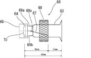
図7は、一方のマウント部68(図6の右側のマウント部68)の拡大図である。このマウント部68においては、ステムマウント63の先端から所定間隔を置いて立設させたリード線69a,69b間にコイル70が張設されるとともに、その外周に、コイル70の黒化を防止するためのニッケルリング65が取り付けられている。また、ステムマウント63の近傍(電極64よりも外側)には、インジウム(水銀と反応することによってアマルガム化しやすい金属)のリング66が配置されている。石英バルブ62の管内には、水銀と希ガスが封入されており、リング66のインジウムは、水銀と反応してアマルガム化する。
FIG. 7 is an enlarged view of one mount portion 68 (the
尚、何らかの要因により、インジウムのリング66が電極64よりも内側の領域に移動してしまった場合、放電の熱により昇温し、紫外線照度低下の原因となる可能性があるため、リング66は、電極64の外側の位置に固定しておく必要がある。このため、図6、図7の例では、リング66は、一端がリード線69cに接続された支柱線67に接合されており、これにより所望の位置に保持、固定されるようになっている。
If the
このアマルガムランプ61においては、インジウムリング66の外側端部からコイル70までの寸法は、電極64からの熱の影響を考慮して、45mmに設定されている。アマルガムランプ61を点灯した場合、インジウムリング66は、放電の熱と電極64からの熱等によって次第に温度が上昇していき、徐々に紫外線照度が上昇して安定した紫外線照度になるが、インジウムリング66の外側端部からコイル70までの寸法が45mmよりも大きいと、点灯後、インジウムリング66が充分な温度に達するまで(即ち、紫外線照度が安定するまで)に時間がかかってしまい、一方、45mmよりも小さい場合には、熱の影響が大き過ぎ、インジウムリング66の温度が必要以上に高くなり、水銀蒸気の圧力が最適値から外れ、却って紫外線照度が落ちてしまうからである。
In this
また、この種のアマルガムランプ61においては、インジウムリング66の外側端部から石英バルブ62の端部までの寸法は、一般に15mm程度に設定されている。
In this type of
図8は、アマルガムをランプ管内に封入したアマルガムランプ71の構成例を示す図である。図示されているように、このアマルガムランプ71においては、ステムマウント73と、電極74(ステムマウント73の先端において所定間隔を置いて立設させたリード線79,79、及び、コイル80によって構成される)が、石英バルブ72内の両端に一組ずつ配置される構成となっている。
FIG. 8 is a diagram showing a configuration example of an
石英バルブ72の内部中央には、アマルガム75が配置されている。アマルガム75は、インジウム(或いは、ビスマス、鉛、スズ等の金属)と、水銀とを合金化したものであり、石英バルブ72の内周面に対し融着されている。尚、この種のアマルガムランプ71においては、一般に、ステムマウント73の高さ(石英バルブ72の端部からコイル80までの寸法)は、35mm程度となるように設計されている。
図6のアマルガムランプ61は、例えば、ランプ電流0.8A、ランプ電力65Wという条件で連続点灯した場合、水銀蒸気が管端部へ移動し、アマルガムランプとしての紫外線特性(温度変化に対する紫外線照度の変動率が小さい)が次第に損なわれ、アマルガムを用いない水銀ランプの紫外線特性(温度変化に対する紫外線照度の変動率が大きい)に近い状態となり、紫外線照度が低下してしまう傾向がある。
For example, when the
以下、この点について具体的に説明する。図6のアマルガムランプ61は、点灯すると、通常は、放電の熱と電極64からの熱等によって、インジウムリング66の温度が次第に上昇していき、徐々に紫外線照度が上昇し、やがて安定するように構成されている。ここで、最冷部(管端部(インジウムリング66よりも外側)における管壁)の温度と、昇温したインジウムリング66の温度との差がそれほど開いていない場合には、管内における水銀蒸気の圧力は、アマルガムによって制御され、管壁の温度における「アマルガムの水銀蒸気圧の値」となり、特に問題は生じない。
Hereinafter, this point will be specifically described. When the
しかしながら、例えば、アマルガムランプ61を水処理装置内にセットして、20℃以下の低温度条件下で連続的に使用するような場合、流動する低温の処理水によって管壁が強制的に冷却されることになるため、管端部の管壁の温度と、インジウムリング66の温度との差が大きく開いてしまうことがある。この場合、インジウムリング66の周囲における水銀蒸気の圧力と比べ、管端部における水銀蒸気の圧力が著しく低くなってしまい、その結果、管内の水銀蒸気が管端部へ移動していき、凝結し、液相の水銀が管端部の管壁に付着してしまうという問題がある。
However, for example, when the
また、図6のアマルガムランプ61を垂直に立てた状態で点灯すると、水銀蒸気が対流によって押し上げられ、ランプ上部の管端部にも水銀が付着してしまうことがある。
Further, when the
インジウムリング66の周囲における水銀蒸気の圧力は、管端部の管壁の温度における「アマルガムの水銀蒸気圧の値」に近くなるはずであるが、液相の純水銀が管端部に存在している場合には、その水銀の周囲における水銀蒸気の圧力は、管端部の管壁の温度における「純水銀の蒸気圧の値」に近くなる。従って、管端部に付着する水銀の量が増加するほど、ランプの紫外線特性は、その分だけ「アマルガムを用いない水銀ランプの紫外線特性(温度変化に対する紫外線照度の変動率が大きい)」に近くなり、高い放射効率を得るための水銀蒸気の圧力範囲、及び、これを実現するための温度条件を満たすことが難しくなり、結果的に紫外線照度が低下してしまうことになる。
The pressure of mercury vapor around the
また、図8のアマルガムランプ71においても、20℃以下の低温度条件下で連続点灯すると、最冷部(管端部の管壁)とアマルガム75の温度差が大きくなり、アマルガム75の周囲における水銀蒸気と、最冷部における水銀蒸気との間で圧力差が生じ、管内の水銀蒸気が最冷部へ移動し、最冷部の管壁に水銀(液相)が付着してしまうことがあり、この場合も、紫外線照度が低下してしまうという問題がある。
Also, in the
また、図8に示したアマルガムランプ71におけるアマルガム75は、前述したように、石英バルブ72の内周面に対し「融着」によって固定されていたため、ランプ71を垂直に立てた状態で長時間点灯させると、熱によりアマルガム75の接着強度が低下して、アマルガム75が石英バルブ72の内周面から剥がれ落ちてしまうことがある。そして、剥がれ落ちたアマルガム75が、電極74に接触した状態、或いは、電極74近傍の位置に留まっているような状態が継続すると、アマルガム75の温度が限度以上に上昇し、最冷部の管壁とアマルガム75の温度差が大きくなり、その結果、上記と同様の理由で紫外線照度が低下してしまうという問題がある。
Further, as described above, the
本発明は、このような従来技術における問題を解決すべくなされたものであって、低温度条件下で使用した場合であっても、アマルガムと最冷部の温度差を小さくすることができ、紫外線照度の低下を防止することができるほか、アマルガムの脱落という問題をも好適に回避することができる高出力殺菌ランプを提供することを目的とする。 The present invention was made to solve such problems in the prior art, and even when used under low temperature conditions, the temperature difference between the amalgam and the coldest part can be reduced, It aims at providing the high output germicidal lamp which can prevent the fall of ultraviolet illuminance and can also avoid the problem of omission of amalgam suitably.
請求項1に記載の殺菌ランプは、300nm以下の紫外線を有効に透過するバルブと、その両端に配置された電極とによって構成され、バルブの管内に、アマルガム、及び、希ガス(又は、水銀と反応してアマルガム化する金属、水銀、及び、希ガス)を封入してなる殺菌ランプであって、電極のうち、少なくとも一方の電極がステムマウントによって支持されるように構成し、ステムマウントの近傍であって、当該ステムマウントによって支持される電極よりも外側の位置に、アマルガム又は水銀と反応してアマルガム化する金属を配置し、バルブに形成されている複数の凸部によってアマルガム又は水銀と反応してアマルガム化する金属が保持されるように構成したことを特徴としている。
The sterilizing lamp according to
尚、アマルガム又は水銀と反応してアマルガム化する金属の外側端部から管端部までの間隔は、10mm以下となるように寸法設定することが好ましく、また、ステムマウントによって支持される電極のコイルからアマルガム又は水銀と反応してアマルガム化する金属の外側端部までの距離は、25〜40mmとなるように寸法設定することが好ましい。更に、電極のうち、一方の電極がステムマウントによって支持されず、リード線とコイルのみによって構成され、当該電極のコイルからバルブの内側端部までの間隔が25mm以下となるように寸法設定することが好ましい。 In addition, it is preferable that the distance from the outer end portion of the metal that amalgamates by reacting with amalgam or mercury to the tube end portion is set to be 10 mm or less, and the coil of the electrode supported by the stem mount The distance from the outer end of the metal that amalgamates to amalgam by reacting with amalgam or mercury is preferably set to 25 to 40 mm. In addition, one of the electrodes is not supported by the stem mount, is constituted only by a lead wire and a coil, and is dimensioned so that the distance from the coil of the electrode to the inner end of the bulb is 25 mm or less. Is preferred.
請求項5に記載の殺菌ランプは、300nm以下の紫外線を有効に透過するバルブと、その両端に配置された電極とによって構成され、前記バルブの管内に、アマルガム、及び、希ガスを封入し、又は、水銀と反応してアマルガム化する金属、水銀、及び、希ガスを封入してなる殺菌ランプであって、アマルガム又は水銀と反応してアマルガム化する金属をリング状に形成して、或いは、アマルガム又は水銀と反応してアマルガム化する金属を、金属製のリング状ホルダーの内周面に固定した状態で、石英バルブの中間部に配置し、バルブに形成されている複数の凸部によって、アマルガム又は前記水銀と反応してアマルガム化する金属又はリング状ホルダーが保持されるように構成したことを特徴としている。 The germicidal lamp according to claim 5 is constituted by a bulb that effectively transmits ultraviolet rays of 300 nm or less and electrodes disposed at both ends thereof, and amalgam and rare gas are enclosed in a tube of the bulb, Or a sterilizing lamp that encloses a metal that amalgamates by reacting with mercury, mercury, and a rare gas, wherein the metal that amalgamates by reacting with amalgam or mercury is formed in a ring shape, or The metal that reacts with amalgam or mercury to become amalgam is fixed to the inner peripheral surface of the metal ring holder, and is arranged in the middle part of the quartz bulb, and by a plurality of convex portions formed on the bulb, A metal gum or ring-shaped holder that is amalgamated by reacting with amalgam or mercury is held.
尚、この場合、電極のコイルからバルブの管端部までの距離は、25mm以下となるように寸法設定することが好ましい。 In this case, it is preferable that the distance from the coil of the electrode to the tube end of the valve is set to be 25 mm or less.
請求項1に記載の殺菌ランプは、アマルガム又は水銀と反応してアマルガム化する金属が、バルブに形成されている凸部17によって保持されるようになっているため、それらを保持するための支柱線を配置する必要がなく、その結果、「支柱線を介した熱伝導によるアマルガム等の高温化」という問題を好適に回避することができる。また、アマルガム等の外側端部から電極のコイルまでの寸法、及び、バルブの端部までの寸法等を適正化することにより、アマルガム等の温度上昇を抑え、低温度条件下で使用した場合でも、最冷部との温度差を小さくすることができ、管内における水銀蒸気の移動、管端部の管壁への水銀の付着という問題を回避することができる。その結果、紫外線照度の低下を好適に防止することができる。
In the sterilizing lamp according to
請求項5に記載の殺菌ランプは、アマルガム等がリング状に形成され、或いは、アマルガム等がホルダーに対して固定され、それがバルブに形成された凸部によって保持される構造となっているため、従来のアマルガムランプのように、アマルガムがバルブの内周面から剥がれ落ちてしまうという問題を好適に回避することができる。また、ステムマウントの高さが適正化されているため、水銀が管端部に付着するという現象を回避することができ、紫外線照度の低下を防止することができる。 The sterilizing lamp according to claim 5 has a structure in which amalgam or the like is formed in a ring shape, or amalgam or the like is fixed to a holder and is held by a convex portion formed in a bulb. And the problem that an amalgam peels off from the internal peripheral surface of a bulb | bulb like the conventional amalgam lamp can be avoided suitably. In addition, since the height of the stem mount is optimized, the phenomenon that mercury adheres to the end of the tube can be avoided, and a decrease in ultraviolet illuminance can be prevented.
以下、本発明の「高出力殺菌ランプ」を実施するための最良の形態について説明する。図1は、本発明の第1の実施形態のアマルガムランプ11の構成図である。このアマルガムランプ11は、0.6A以上のランプ電流を用いるタイプのランプであり、300nm以下の紫外線を有効に透過する石英バルブ12と、その両端に一つずつ配置される電極14(14a,14b)とによって構成されている。尚、図示されているように、二つの電極14a,14bのうち、一方(図中右側の電極14a)はステムマウント13によって保持されているのに対し、他方(図中左側の電極14b)は、リード線19とコイル20bのみによって構成されている。
Hereinafter, the best mode for carrying out the “high output sterilization lamp” of the present invention will be described. FIG. 1 is a configuration diagram of an
また、図示されているように、ステムマウント13側の電極14aの外周には、コイル20aの黒化を防止するためのニッケルリング15が取り付けられている。そして、ステムマウント13の近傍には、水銀と反応してアマルガム化するインジウムのリング16が配置されている。石英バルブ12の管内には、水銀と希ガスが封入されており、リング16のインジウムは、水銀と反応してアマルガム化する。
Further, as shown in the figure, a
前述したように、従来のアマルガムランプ61(図6、図7参照)は、20℃以下の低温度条件下で使用する場合、インジウムリング66と管端部の管壁との間で著しい温度差が生じ、その結果、水銀が管端部の管壁に付着し、紫外線照度が低下してしまうという問題があり、本発明の発明者らがこの問題について研究を行った結果、次の二つの事項が主たる要因となっていることが判明した。
As described above, the conventional amalgam lamp 61 (see FIGS. 6 and 7) has a significant temperature difference between the
図6のアマルガムランプ61においては、インジウムリング66が支柱線67を介してリード線69cに接続、保持されているため、電極64からの熱伝導率が高く、インジウムリング66の温度が必要以上に高くなってしまう、ということと、インジウムリング66の外側端部から石英バルブ62の端部までの間隔(一般に15mm程度)が広すぎるため、温度差が生じやすく、また、解消しにくい、ということである。
In the
本実施形態のアマルガムランプ11では、インジウムリング16は、石英バルブ12に形成されている凸部17,17(内周面から管の中心軸に向かって突出した突起)によって挟まれるような構成となっており、これによって、管の長手方向についてのインジウムリング16の移動が規制され、所定の位置に保持されるようになっている。従って、本実施形態のアマルガムランプ11においては、インジウムリング16を保持するための支柱線を配置する必要がなく、その結果、「支柱線を介した熱伝導によるインジウムリング16の高温化」という問題を好適に回避することができる。
In the
尚、凸部17,17は、石英バルブ12を部分的に加熱し、軟化させて、石英バルブ12の壁面の一部を外周面側から管の中心軸に向かって部分的に押し込んで、凹ませることによって形成する。
The
ところで、図6の従来のアマルガムランプ61においては、インジウムリング66の外側端部からコイル70までの寸法は45mmに設定されているが、この寸法設定は、「支柱線67を介した熱伝導」を考慮した上でのものであるため、本実施形態のアマルガムランプ11のように、支柱線を省略した構造のものに、この寸法設定をそのまま適用することには問題がある。そこで、本発明の発明者らは、図1に示したような構造のアマルガムランプ11における当該寸法(インジウムリング16の外側端部からコイル20aまでの寸法)の適正範囲について研究を行った。
By the way, in the
その結果、この寸法が40mmを超えている場合、アマルガムランプ11の点灯開始後、紫外線照度が安定するまでに時間がかかり過ぎる(30分以上かかる)ことが判明し、また、25mm未満である場合、点灯開始後、紫外線照度がピークに達するまでの時間は短くなるものの、ピーク後に紫外線照度が低下してしまうことが判明した。このため、本実施形態においては、当該寸法は30mmに設定されている。但し、25〜40mmの範囲であれば、寸法設定を変更してもよい。
As a result, when this dimension exceeds 40 mm, it turns out that it takes too much time (it takes 30 minutes or more) for the UV illuminance to stabilize after the start of lighting of the
更に、本実施形態においては、インジウムリング16の外側端部から石英バルブ12の端部までの寸法は10mmに設定されている。この寸法が10mmを超えている場合、管端部とインジウムリング16との間で温度差が生じやすく、解消しにくいということが判っており、また、10mm以下であれば温度差を小さくできるということが、発明者らの実験によって確認されている。
Furthermore, in the present embodiment, the dimension from the outer end of the
一方、ステムマウントが配置されていない方のコイル20bから、石英バルブ12の内側端部18までの寸法は、20mmに設定されている。この寸法が25mmを超えている場合、点灯時において水銀が端部18に付着する傾向があり、安定後の紫外線照度が低下してしまうことが判っており、本実施形態においては、上述の通り20mmに設定されているが、25mm以下であれば、寸法設定を変更してもよい。
On the other hand, the dimension from the
このように、本実施形態のアマルガムランプ11においては、インジウムリング16がリード線19には接続されておらず、石英バルブ12に形成されている凸部17,17によって保持される構造となっており、かつ、インジウムリング16の外側端部からコイル20aまでの寸法が25〜40mmの範囲内となるように設定され、また、インジウムリング16の外側端部から石英バルブ12の端部までの寸法が10mm以下に設定され、更に、ステムマウントが配置されていない方のコイル20bから、石英バルブ12の内側端部18までの寸法が25mm以下に設定されているため、インジウムリング16の温度上昇が少なく、低温度条件下で使用した場合でも、最冷部との温度差を小さくすることができ、管内における水銀蒸気の移動、管端部の管壁への水銀の付着という問題を好適に回避することができる。
Thus, in the
尚、石英バルブ12の管径は18mm、管長は1005mm、肉厚0.9mmとなっており、ステムマウント13の高さ(石英バルブ12の端部から電極14のコイル20aまでの寸法)は、40mmに設定されている。
The
また、本実施形態においては、石英バルブ12の管内に水銀と希ガスが封入され、リング16のインジウムと水銀が反応してアマルガム化するように構成されているが、最初からアマルガムを封入してもよい。また、本実施形態においては、コイルの黒化を防止するためのニッケルリング15が、ステムマウント13側のコイル20aの外周に配置されているが、このニッケルリング15は省略することができる。また、ステムマウントが配置されていない方のコイル20bの外周にニッケルリングを配置してもよい。
In this embodiment, mercury and a rare gas are enclosed in the tube of the
図2は、本発明の第2の実施形態に係る高出力殺菌ランプ(アマルガムランプ21)の構成図である。このアマルガムランプ21も、0.6A以上のランプ電流を用いるタイプのランプであり、300nm以下の紫外線を有効に透過する石英バルブ22と、その両端に一つずつ配置される電極24,24とによって構成されている。尚、電極24,24は、それぞれステムマウント23,23によって支持されている。
FIG. 2 is a configuration diagram of a high-power sterilizing lamp (amalgam lamp 21) according to the second embodiment of the present invention. This
石英バルブ22の管径は18mm、管長は1005mm、肉厚0.9mmとなっており、ステムマウント23の高さ(石英バルブ22の端部から電極24のコイル30までの寸法)は、左右いずれも25mm(25mm以下)に設定されている。
The
このアマルガムランプ21の管内には、アマルガム25と希ガスが封入されている。尚、アマルガム25は、石英バルブ22の内周面に対して接着されているのではなく、図2に示されているように、金属製のホルダー26を介して固定されている。より具体的に説明すると、ホルダー26は、外径が、石英バルブ22の内径よりも僅かに小さく(約16mm)、軸線方向に約8mmの幅を有するリング状(筒状)になっており、図3に示すように、周面全体がメッシュ状になっている。そして、アマルガム25は、このリング状のホルダー26の内周面に対して圧着されており、ホルダー26は、内側にアマルガム25を保持した状態で、石英バルブ22の管内に配置されている。
In the tube of the
更に、石英バルブ22には、ホルダー26を固定するための凸部27,27(内周面から管の軸線に向かって突出した突起)が、ホルダー26の配設位置の両側に形成されており、管の長手方向についてのホルダー26の移動が規制され、所定位置に保持されるようになっている。
Further, the
尚、凸部27,27は、石英バルブ22を部分的に加熱し、軟化させて、石英バルブ22の壁面の一部を外周面側から管の中心軸に向かって部分的に押し込んで、凹ませることによって形成する。
The
尚、本実施形態においては、アマルガム25がホルダー26に固定された状態で管内に封入されているが、インジウムや鉛などの金属(水銀と反応することによってアマルガム化しやすい金属、或いは、その合金)をホルダー26に固定して、或いは、そのような金属をリング状に形成して、水銀とともに管内に封入してもよい。また、アマルガム25とホルダー26は、一つのアマルガムランプ21について1セットだけを封入してもよいし、複数セットを封入してもよい。
In the present embodiment, the
このアマルガムランプ21は、上述したような構造にかかるものであるところ、アマルガム25の脱落という問題を回避することができ、また、紫外線照度の低下という問題を回避することができる。具体的には、アマルガム25がメッシュ状のホルダー26に対して圧着され、ホルダー26は石英バルブ22の凸部27,27によって保持されているため、管の長手方向についての移動を規制し、所定の位置に固定することができる。
The
また、ステムマウント23の高さ(石英バルブ22の端部から電極24のコイル30までの寸法)が、左右いずれも25mmに設定されているため、水銀が管端部に付着するという現象を好適に回避することができ、紫外線照度の低下を防止することができる。
Further, since the height of the stem mount 23 (the dimension from the end of the
この点について具体的に説明すると、石英バルブ72(図8参照)の中間部(二つの電極74,74の間の領域)にアマルガム75(或いは、アマルガム化しやすい金属)を配置した従来のアマルガムランプ71においては、ステムマウント73の高さが35mm程度に設定されていたが、この寸法が25mmを超えていると、低温度条件下で使用するような場合に、管端部の温度とアマルガム75の温度の差が限度以上に大きくなってしまうことがあり、継続して点灯すると、水銀が管端部に付着して紫外線照度が低下してしまうという問題があったが、発明者らが行った研究の結果、この寸法を25mm以下に設定すれば、管端部とアマルガム75の間の温度差を小さくすることができ、紫外線照度の低下を防止できることが判明した。
This point will be described in detail. A conventional amalgam lamp in which an amalgam 75 (or a metal that is easily amalgamated) is disposed in an intermediate portion (region between two
そこで、本実施形態においては、ステムマウント23の高さ(石英バルブ22の端部から電極24のコイル30までの寸法)を、左右いずれも25mmに設定している。但し、「25mm」に限定する必要はなく、25mm以下の任意の寸法に設定してもよい。
Therefore, in the present embodiment, the height of the stem mount 23 (the dimension from the end of the
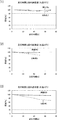
次に、本発明の実施例について説明する。まず、本発明の実施例1として、図1に示したアマルガムランプ11を用意し、これを垂直に立てた状態で(ステムマウント13側の端部が上方となる向きで)水処理装置内に取り付け、ランプ電流0.8Aを通電して連続点灯し、経時的に紫外線照度を計測した。尚、この実験は、水処理装置内の水温条件を変えて3回行った(第1回目は水温を25℃、第2回目は20℃、第3回目は10℃とした)。また、比較例1として、図6に示したアマルガムランプ61を用意し、実施例1と同一条件下で紫外線照度を計測した。その結果を図4に示す。
Next, examples of the present invention will be described. First, as Example 1 of the present invention, the
図4(1)は、水処理装置内の水温を25℃に設定した場合における紫外線照度の経時変化を示すグラフである。比較例1、実施例1ともに、点灯開始から70時間が経過しても照度は殆ど低下しなかった。 FIG. 4 (1) is a graph showing a change with time in ultraviolet illuminance when the water temperature in the water treatment apparatus is set to 25 ° C. In both Comparative Example 1 and Example 1, the illuminance hardly decreased even after 70 hours had elapsed since the start of lighting.
図4(2)は、水処理装置内の水温を20℃に設定した場合における紫外線照度の経時変化を示すグラフである。比較例1は、点灯開始から50時間が経過した時点で、照度は約80%程度まで下がったが、実施例1は、70時間が経過しても殆ど低下しなかった。 FIG. 4 (2) is a graph showing the change with time in the ultraviolet illuminance when the water temperature in the water treatment apparatus is set to 20 ° C. In Comparative Example 1, the illuminance decreased to about 80% when 50 hours passed from the start of lighting, but Example 1 hardly decreased even after 70 hours passed.
図4(3)は、水処理装置内の水温を10℃に設定した場合における紫外線照度の経時変化を示すグラフである。比較例1は、点灯開始から70時間が経過した時点で、照度は70%以下まで下がったが、実施例1は、70時間が経過しても殆ど低下しなかった。 FIG. 4 (3) is a graph showing a change with time in ultraviolet illuminance when the water temperature in the water treatment apparatus is set to 10 ° C. In Comparative Example 1, the illuminance decreased to 70% or less when 70 hours passed from the start of lighting, but Example 1 hardly decreased even after 70 hours passed.
また、実施例1においては、管端部への水銀の付着は見られず、紫外線照度の低下もなく、良好な結果が得られた。更に、実施例1の上下を入れ替えた場合、及び、実施例1を横向きに取り付けた場合のいずれにおいても、同様の効果が確認された。 Moreover, in Example 1, the adhesion of mercury to the tube end portion was not observed, and there was no decrease in ultraviolet illuminance, and good results were obtained. Furthermore, the same effect was confirmed in both cases where the upper and lower sides of Example 1 were exchanged and where Example 1 was mounted sideways.
次に、本発明の実施例2として、図2に示したアマルガムランプ21を用意し、これを垂直に立てた状態で水処理装置内に取り付け、ランプ電流0.8Aを通電して連続点灯し、経時的に紫外線照度を計測した。尚、この実験も、水処理装置内の水温条件を変えて3回行った(第1回目は水温を25℃、第2回目は20℃、第3回目は10℃とした)。また、比較例2として、図8に示したアマルガムランプ71を用意し、実施例2と同一条件下で紫外線照度を計測した。その結果を図5に示す。
Next, as Example 2 of the present invention, an
図5(1)は、水処理装置内の水温を25℃に設定した場合における紫外線照度の経時変化を示すグラフである。比較例2は、点灯開始から60時間が経過した時点で、照度は約90%程度まで下がったが、実施例2は、70時間が経過しても殆ど低下しなかった。 FIG. 5 (1) is a graph showing a change with time in ultraviolet illuminance when the water temperature in the water treatment apparatus is set to 25 ° C. In Comparative Example 2, when 60 hours passed from the start of lighting, the illuminance decreased to about 90%, but in Example 2, almost no decrease was observed even after 70 hours passed.
図5(2)は、水処理装置内の水温を20℃に設定した場合における紫外線照度の経時変化を示すグラフである。比較例2は、点灯開始から50時間が経過した時点で、照度は約80%程度まで下がったが、実施例2は、50時間が経過しても殆ど低下しなかった。 FIG. 5 (2) is a graph showing a change with time in ultraviolet illuminance when the water temperature in the water treatment apparatus is set to 20 ° C. In Comparative Example 2, when 50 hours passed from the start of lighting, the illuminance decreased to about 80%, but in Example 2, almost no decrease was observed even after 50 hours passed.
図5(3)は、水処理装置内の水温を10℃に設定した場合における紫外線照度の経時変化を示すグラフである。比較例2は、点灯開始から70時間が経過した時点で、照度は約70%程度まで下がったが、実施例2は、70時間が経過しても95%以下には低下しなかった。 FIG. 5 (3) is a graph showing the change over time in the ultraviolet illuminance when the water temperature in the water treatment apparatus is set to 10 ° C. In Comparative Example 2, when 70 hours passed from the start of lighting, the illuminance dropped to about 70%, but in Example 2, it did not decrease to 95% or less even after 70 hours passed.
また、実施例2においては、アマルガムの脱落は見られず、紫外線照度の立ち上がりも良く、良好な結果が得られた。更に、実施例2を横向きに取り付けた場合も同様の効果が確認された。 Moreover, in Example 2, the amalgam did not fall off, and the rising of the ultraviolet illuminance was good, and good results were obtained. Furthermore, the same effect was confirmed when Example 2 was mounted sideways.
11,21,61,71:アマルガムランプ、
12,22,62,72:石英バルブ、
13,23,63,73:ステムマウント、
14,14a,14b,24,64,74:電極、
15,65:ニッケルリング、
16,66:リング、
17,27:凸部、
18:内側端部、
19,69a,69b,69c,79:リード線、
20a,20b,30,70,80:コイル、
25,75:アマルガム、
26:ホルダー、
67:支柱線、
68:マウント部
11, 21, 61, 71: Amalgam lamp,
12, 22, 62, 72: quartz bulb,
13, 23, 63, 73: stem mount,
14, 14a, 14b, 24, 64, 74: electrodes,
15, 65: Nickel ring,
16, 66: Ring,
17, 27: convex part,
18: inner end,
19, 69a, 69b, 69c, 79: lead wires,
20a, 20b, 30, 70, 80: coil,
25,75: Amalgam,
26: Holder,
67: Strut wire,
68: Mount part
Claims (6)
前記電極のうち、少なくとも一方の電極がステムマウントによって支持されるように構成し、
前記ステムマウントの近傍であって、当該ステムマウントによって支持される電極よりも外側の位置に、前記アマルガム又は水銀と反応してアマルガム化する金属を配置し、
前記バルブに形成されている凸部によって前記アマルガム又は水銀と反応してアマルガム化する金属が保持されるように構成したことを特徴とする殺菌ランプ。 It is composed of a bulb that effectively transmits ultraviolet rays of 300 nm or less and electrodes arranged at both ends thereof, and amalgam and rare gas are sealed in the bulb of the bulb or amalgamated by reacting with mercury. In an amalgam sterilization lamp in which metal, mercury, and a rare gas are enclosed,
Among the electrodes, at least one electrode is configured to be supported by a stem mount,
In the vicinity of the stem mount, at a position outside the electrode supported by the stem mount, a metal that reacts with the amalgam or mercury and amalgamates is disposed,
A sterilizing lamp configured to hold the metal that amalgamates by reacting with the amalgam or mercury by a convex portion formed on the bulb.
前記アマルガム又は水銀と反応してアマルガム化する金属をリング状に形成して、或いは、前記アマルガム又は水銀と反応してアマルガム化する金属を、金属製のリング状ホルダーの内周面に固定した状態で、前記石英バルブの中間部に配置し、
前記バルブに形成されている凸部によって、前記アマルガム又は前記水銀と反応してアマルガム化する金属又はリング状ホルダーが保持されるように構成したことを特徴とする殺菌ランプ。 It is composed of a bulb that effectively transmits ultraviolet rays of 300 nm or less and electrodes arranged at both ends thereof, and amalgam and rare gas are sealed in the bulb of the bulb or amalgamated by reacting with mercury. In an amalgam sterilization lamp in which metal, mercury, and a rare gas are enclosed,
A state in which the metal that amalgamates by reacting with the amalgam or mercury is formed in a ring shape, or the metal that amalgamates by reacting with the amalgam or mercury is fixed to the inner peripheral surface of a metal ring-shaped holder In the middle of the quartz bulb,
A sterilizing lamp characterized in that a metal or ring-shaped holder that amalgamates by reacting with the amalgam or mercury is held by a convex portion formed on the bulb.
Priority Applications (1)
| Application Number | Priority Date | Filing Date | Title |
|---|---|---|---|
| JP2006124943A JP2007299563A (en) | 2006-04-28 | 2006-04-28 | High power sterilizer lamp |
Applications Claiming Priority (1)
| Application Number | Priority Date | Filing Date | Title |
|---|---|---|---|
| JP2006124943A JP2007299563A (en) | 2006-04-28 | 2006-04-28 | High power sterilizer lamp |
Publications (1)
| Publication Number | Publication Date |
|---|---|
| JP2007299563A true JP2007299563A (en) | 2007-11-15 |
Family
ID=38768895
Family Applications (1)
| Application Number | Title | Priority Date | Filing Date |
|---|---|---|---|
| JP2006124943A Pending JP2007299563A (en) | 2006-04-28 | 2006-04-28 | High power sterilizer lamp |
Country Status (1)
| Country | Link |
|---|---|
| JP (1) | JP2007299563A (en) |
Cited By (3)
| Publication number | Priority date | Publication date | Assignee | Title |
|---|---|---|---|---|
| JP2011258321A (en) * | 2010-06-07 | 2011-12-22 | Iwasaki Electric Co Ltd | Amalgam type low-pressure mercury lamp and power unit for lighting the same |
| EP2779210A1 (en) * | 2013-03-14 | 2014-09-17 | Heraeus Noblelight GmbH | Mercury vapour discharge lamp and method for its production |
| JP2016536082A (en) * | 2013-09-27 | 2016-11-24 | 何志明 | Ultraviolet sterilizer and disposition method thereof |
-
2006
- 2006-04-28 JP JP2006124943A patent/JP2007299563A/en active Pending
Cited By (3)
| Publication number | Priority date | Publication date | Assignee | Title |
|---|---|---|---|---|
| JP2011258321A (en) * | 2010-06-07 | 2011-12-22 | Iwasaki Electric Co Ltd | Amalgam type low-pressure mercury lamp and power unit for lighting the same |
| EP2779210A1 (en) * | 2013-03-14 | 2014-09-17 | Heraeus Noblelight GmbH | Mercury vapour discharge lamp and method for its production |
| JP2016536082A (en) * | 2013-09-27 | 2016-11-24 | 何志明 | Ultraviolet sterilizer and disposition method thereof |
Similar Documents
| Publication | Publication Date | Title |
|---|---|---|
| CN100449678C (en) | Short arc ultra-high pressure mercury lamp | |
| JP5023959B2 (en) | High pressure discharge lamp and high pressure discharge lamp apparatus | |
| GB2203283A (en) | Lamp for generating ultraviolet radiation | |
| JP4993115B2 (en) | High pressure discharge lamp | |
| JP4042588B2 (en) | Discharge lamp | |
| JP2006134710A (en) | Metal halide lamp | |
| JP4525798B2 (en) | Short arc type mercury lamp | |
| JP2007299563A (en) | High power sterilizer lamp | |
| TW200814840A (en) | Compact HID arc lamp having shrouded arc tube and helical lead wire | |
| CN104051223A (en) | Mercury vapor discharge lamp and method for its manufacture | |
| JP4400125B2 (en) | Short arc type discharge lamp lighting device | |
| WO2012176493A1 (en) | Mercury-free metal halide lamp for vehicle and metal halide lamp device | |
| KR101821898B1 (en) | a xenon flash lamp | |
| JP4026513B2 (en) | Discharge lamp | |
| JP2010257703A (en) | Discharge lamp and manufacturing method thereof | |
| JP4879383B2 (en) | Discharge lamp | |
| JP7692778B2 (en) | Discharge lamp and method of manufacturing electrode for discharge lamp | |
| JP4973509B2 (en) | Short arc type high pressure discharge lamp | |
| JP7072786B2 (en) | Low-pressure mercury lamp and its manufacturing method | |
| JP2009105062A (en) | Short arc super high pressure mercury lamp | |
| JP6692522B2 (en) | Low-pressure mercury lamp and device using the same | |
| JP2010251334A (en) | Discharge lamp | |
| JP2001291488A (en) | Double ring fluorescent lamp | |
| CN102315081A (en) | The location of Auxiliary amalgam | |
| JP2006269081A (en) | Short arc discharge lamp |