JP2007299599A - Ring lamp - Google Patents
Ring lamp Download PDFInfo
- Publication number
- JP2007299599A JP2007299599A JP2006125763A JP2006125763A JP2007299599A JP 2007299599 A JP2007299599 A JP 2007299599A JP 2006125763 A JP2006125763 A JP 2006125763A JP 2006125763 A JP2006125763 A JP 2006125763A JP 2007299599 A JP2007299599 A JP 2007299599A
- Authority
- JP
- Japan
- Prior art keywords
- light guide
- lens
- ring
- light
- guide arm
- Prior art date
- Legal status (The legal status is an assumption and is not a legal conclusion. Google has not performed a legal analysis and makes no representation as to the accuracy of the status listed.)
- Pending
Links
Images




Landscapes
- Non-Portable Lighting Devices Or Systems Thereof (AREA)
Abstract
【課題】従来のリング状ランプにおいては、高屈折率の透明材であるコアを低屈折率の透明材であるクラッドで覆い発光部を形成し、更に、コアとクラッドの間に反射層を形成する構成であったので、発光部の形成に大変に手間がかかり高価となっていた。
【解決手段】本発明により、リング状板として形成された導光レンズ2の中心にLED4を放射状に複数配置すると共に、夫々のLEDの光軸方向から導光レンズに至り導光アーム5を一体化して設置し、導光レンズと導光アームとの交点には、導光アームを伝播してくるLEDからの光を導光レンズの形成された円周方向に反射する反射部2aが設けられている構成のリング状ランプ1を基本とし、多層化、或いは、リフレクタ10などと組合わせることで安価で多様なリング状ランプの形成を可能とし課題を解決する。
【選択図】図1
In a conventional ring lamp, a core that is a transparent material having a high refractive index is covered with a clad that is a transparent material having a low refractive index to form a light emitting portion, and a reflective layer is formed between the core and the cladding. Therefore, the formation of the light emitting portion is very time-consuming and expensive.
According to the present invention, a plurality of LEDs 4 are arranged radially at the center of a light guide lens 2 formed as a ring-shaped plate, and the light guide arm 5 is integrated with the light guide lens from the optical axis direction of each LED. The reflection part 2a that reflects light from the LED propagating through the light guide arm in the circumferential direction on which the light guide lens is formed is provided at the intersection of the light guide lens and the light guide arm. The ring-shaped lamp 1 having the structure as described above is used as a base, and by combining with a multilayer structure or a reflector 10 or the like, various ring-shaped lamps can be formed at low cost and the problem is solved.
[Selection] Figure 1
Description
本発明は、リング状に発光を行う灯具の構成に係るものであり、例えば、ヘッドライトなど照明用灯具の周縁に設けられて、車両など装飾的効果を一層に向上させ、商品価値の向上を演出するときに用いる際に用いられる。 The present invention relates to a configuration of a lamp that emits light in a ring shape.For example, the lamp is provided at the periphery of an illumination lamp such as a headlight to further improve a decorative effect such as a vehicle and improve the commercial value. It is used when used when producing.
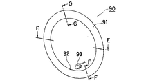
従来のこの種のリング状ランプ90の構成としては、全体的には、図9、図10に示すような形状に形成されており、丸棒をリング状に形成した発光部91の一部には、前記発光部91の径方向に沿う略V字状の切欠部92が少なくとも1箇所設けられており、この切欠部92にはLEDランプ93が対峙されて発光部91内に光が導入されるように構成されている。
A conventional ring-
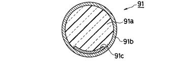
ここで、図11、図12に示すものは、前記発光部91の断面図であって、この発光部91を形成する丸棒自体が多層の構成とされ、まず、前記発光部91の中心部は、例えば、アクリル樹脂、ポリカーボネート樹脂など、比較的に屈折率の高い樹脂でコア91aが形成されており、その外周には、ポリエチレン、ポリプロピレンなど比較的に屈折率の低い樹脂で被膜(クラッド)91bが形成されている。
Here, FIGS. 11 and 12 are cross-sectional views of the light-emitting
また、前記切欠部92が設けられた側のコア91aと被膜91bとの間には、発光部91内を周回している光を外部に放出させるための反射層91cが形成され、この反射層91cは、図12に示すように、前記LEDランプ93から遠い場所ほど広い幅として形成されて、前記発光部91の全面から均一な明るさの光が放射されるように配慮されている。
しかしながら、前記した従来の構成のリング状ランプ90においては、丸棒状で且つリング状とした発光部91を形成すること、即ちコア91a部分を形成することは、ヒケなどの問題を生じやすく、かなりに困難な作業工程となり、更に加えて、コア91aを覆う被覆(クラッド)91b、及び、反射層91cを形成するのは更に困難な作業工程となる。
However, in the above-described ring-
よって、発光部91は、生産性が低くなり、コスト高なものとなる可能性が高く、リング状ランプ90自体がコスト高のものとなり、安価で大量生産が要求される車両用の装飾部品などとして使用するという目的には適さないものとなる問題点を生じる。
Therefore, the
また、上記のように発光部91を、丸棒のリング状として形成した場合には、外部に放出される光は全てが略半円状のレンズ状部分を通過するものとなり、広い範囲に拡散するものとなって、予定するほどの明るさが得られず、この明るさを充分なものとするときには多数のLEDランプを使用しなければ成らず、構成が煩雑化する問題点も生じていた。
Further, when the
本発明は、上記した従来の課題を解決するための具体的な手段として、リング状板として形成された導光レンズの中心にLEDを放射状に複数配置すると共に、夫々の前記LEDの光軸方向から前記導光レンズに至り導光アームを一体化して設置し、前記導光レンズと前記導光アームとの交点には、前記導光アームを伝播してくる前記LEDからの光を前記導光レンズの形成された円周方向に反射する反射部が設けられていることを特徴とするリング状ランプを提供することで、構成と組立作業を単純化し、コストダウンを可能として課題を解決するものである。 In the present invention, as specific means for solving the above-described conventional problems, a plurality of LEDs are arranged radially in the center of a light guide lens formed as a ring-shaped plate, and the optical axis direction of each of the LEDs From the LED to the light guide lens, a light guide arm is integrated and installed, and light from the LED propagating through the light guide arm is guided to the intersection of the light guide lens and the light guide arm. By providing a ring-shaped lamp that is provided with a reflecting portion that reflects in the circumferential direction on which the lens is formed, the configuration and assembly work can be simplified, and the cost can be reduced to solve the problem. It is.
本発明により、板状のリングを使用し、このリングの中心にチップ状のLEDを配置し、放射状に導光アームでリングで直結させることで、LEDからの光がそれ程にロスを生じない状態でリングに達するものとなり、また、リングから外部に放出されるときも、平面から放出されるものとなり極度の拡散を受けない状態となり、よって、少ないLEDの数においても明るいリング状ランプが得られるという効果が得られるものとなる。 According to the present invention, a plate-like ring is used, a chip-like LED is arranged at the center of this ring, and the light from the LED does not cause much loss by being directly connected by a ring with a light guide arm radially. And when it is emitted from the ring to the outside, it is emitted from the plane and is not subject to extreme diffusion, and thus a bright ring-shaped lamp can be obtained even with a small number of LEDs. The effect is obtained.
つぎに、本発明を図に示す実施形態に基づいて詳細に説明する。図1に符号1で示すものは、本発明に係るリング状ランプの第一実施例であり、本発明においてはリング状ランプ1のリング部である導光レンズ2は基本的には板状の形状として形成されている。
Below, this invention is demonstrated in detail based on embodiment shown in a figure. 1 is a first embodiment of a ring-shaped lamp according to the present invention. In the present invention, the
そして、前記導光レンズ2に対して、略同一平面内であり、且つ、略中心の位置には、多角形、例えば、四角形、五角形、六角形など多辺形の基板3が設置され、前記多辺形とされたそれぞれの辺3aには、光源であるLEDチップ4が取付けられている。尚、このときに、前記基板3はセラミクス、ガラスエポキシ樹脂など適宜の絶縁物で形成され、各LEDチップ4に給電が行えるように配線パターン(図示は省略する)の形成などが行われ、前記基板3の辺3aに取付けられたLEDチップ4は、点灯と消灯とが自在に行える構成とされている。また、前記基板3にフレキシブルプリント基板を用いて配線を行うことや、前記基板に代えてアルミニウムなどの金属基板を用いるようにしても良い。
Then, a polygonal substrate, for example, a
このときに、前記基板3とLEDチップ4とは、前記LEDチップ4を湿度など外部環境から保護するために、例えば、透明なエポキシ樹脂などによりモールデイングが行われ、外気に対して気密が保てる構成とされている。
At this time, the
加えて、本発明では、夫々の前記LEDチップ4に対応して導光アーム5が設けられるものとされており、夫々の前記LEDチップ4から発光された光は、それぞれに対応して設けられた導光アーム5の一方の端部5aから導光アーム5内に導入され、導光されるものとされる。
In addition, in the present invention, the
そして、前記導光アーム5の他方の端部5bは前記導光レンズ2の内径に接続されているものとされているので、前記LEDチップ4から発せられた光は、前記導光レンズ2内に導入されるものとなる。尚、このときには、前記導光アーム5の他方の端部5bと、前記導光レンズ2とは、直角に近い角度で接続されているものとなるので、双方が透明である場合には、内部反射を行わず、LEDチップ4からの光は、そのまま直進し、前記導光レンズ2の外径側から外部に放出してしまう可能性が高い。
Since the
よって、図1にも示すように、前記導光アーム5と接続されている位置の前記導光レンズ2の外径側には、導光アーム5からの光が内面全反射を行う角度として当接するような、略V字状とした反射部2aを形成しておき、この反射部2aにより光を反射させ、前記導光レンズ2内に閉じこめるようにしてある。よって、前記LEDチップ5からの光は導光レンズ2内に存在するものとされている。
Therefore, as shown in FIG. 1, the light beam from the
ここで、前記導光レンズ2、前記反射部2a、導光アーム5の全ての外気と接する面が平滑面であると、一旦、内面に閉じこめられた光は、上記した導光レンズ2など高屈折部材内で内面反射を繰り返すものとなり、表面には光は放出されることはない。即ち、灯具としての目的を達するものとは成らない。
Here, if the surfaces of the
そこで、本発明では図2に示すように、前記導光レンズ2の観視面2bに対峙する側の面(以下、背面と称する)に適宜な形状のレンズカット2cを設ければ、観視面2bを発光させることができる。尚、上記は導光アーム5においても同様であり、前記導光アーム5の観視面5cに対峙する側の面(背面)にレンズカット5dを設けておけば、前記導光アーム5も発光部分として使用可能となり、全体のデザインに変化を与えられるものとなる。
Therefore, in the present invention, as shown in FIG. 2, if a lens cut 2 c having an appropriate shape is provided on a surface (hereinafter referred to as a back surface) facing the
尚、このときに、前記導光レンズ2の観視面2bを光らせたい場所に対応する背面2dにレンズカット2cを施しておけば、導光レンズ2は所望の部分が光るものとなり、例えば、導光レンズ2を破線状の円弧などとして光輝させることも可能である。そして、これは、導光アーム5に対しても、全く同様に実施することが可能である。
At this time, if the lens cut 2c is applied to the
また、本発明では、導光レンズ2の観視面2b、或いは、導光アーム5の観視面5c側にも加工を行い見栄えの向上などを図ることが可能であり、上記のように導光レンズ2の背面2d、或いは、導光アーム5の背面5eのレンズカット2c、5dに対応する観視面2b、5c側に梨地加工など微細な凹凸加工を施しておけば、外部に射出される光は一層に均一度の高いものとなり、品質感、美観の向上が可能となる。
In the present invention, it is possible to process the
図3、図4は、第二実施例を示すものであり、本発明は上記に説明した第一実施例のように導光アーム5が1枚であっても良いが、例えば、2枚など複数であっても良い。
3 and 4 show a second embodiment, and the present invention may have only one
この第二実施例の場合、前の実施例と同様に導光レンズ2は一枚であり、この導光レンズ2に対して、例えば、4個のLEDチップ4を有する導光アーム51が設けられている点も同様であるが、これに加えて、前記導光レンズ2に対して、同様に4個のLEDチップ4を有する導光アーム52が下方にも設けられるものとされ、前記導光アーム51と導光アーム52とは、等角度で前記導光レンズ2の内周を分割するように配置されている。
In the case of this second embodiment, there is one
そして、下方に配置された導光アーム52の一方の端部52aにはLEDチップ4が対峙しており、他方の端部52b側には折曲反射部6が設けられて、前記導光アーム52からの光を略直角に上方に折り曲げて、前記導光レンズ2に接続されている。よって、前記導光レンズ2には内径側の4箇所に導光アーム51からの光が導入され、背面側の4箇所に導光アーム52からの光が導入されている。
The
尚、前記導光アーム51が接続された導光レンズ2の外径側には反射部2aが設けられている点、同じく前記導光レンズ2の背面2dの必要部分にはレンズカット2cが施されている点、観視面2b側に梨地加工などが必要に応じて施されている点は第一実施例と同様である。
Incidentally, a reflecting
図5、図6に示すものは、本発明の第三実施例であり、この第三実施例においても、図5に示すように、導光レンズ2、及び、導光アーム5の部分の構成はほぼ同様であり、正面から見たときの形状もほぼ同様であるが、このリング状ランプ1を正面から見た状態で前記導光レンズ2、及び、導光アーム5との下方(図6も参照)に、前記導光レンズ2、導光アーム5と平行に、LEDチップ4が搭載された第二基板8が設置されている。
5 and 6 show a third embodiment of the present invention. In this third embodiment as well, as shown in FIG. 5, the configuration of the
このときに、前記第二基板8上には複数のLEDチップ4が搭載されているが、これらLEDチップ4は、発光方向と設置位置とを前記導光レンズ2と導光アーム5とで囲まれる間隙部7に対応するものとされており、よって、この第三実施例のリング状ランプ1を正面から見るときには、前記第二基板8上に設置されたLEDチップ4からの光は、前記導光レンズ2と導光アーム5とに遮られることがないものとされている。
At this time, a plurality of
加えて、前記導光レンズ2と前記第二基板8の間には、第二基板8上に設置されたLEDチップ4に対応するレンズカット9a、例えば、LEDチップ4に焦点を合わせた凸レンズ状のカットが施されたインナーレンズ9が取付けられている。
In addition, between the
以上の構成としたことで、この第三実施例のリング状ランプ1は、正面視では図5に示すような形状に見えるものとなり、点灯時には、導光レンズ2と導光アーム5とが、それらの背面に施されたレンズカット2c、5dにより均一で比較的に暗い状態で光輝している間接光的な光と、第二基板8上の照射方向に向けられたLEDチップ4からの直射光的な光とが組合わされ、斬新な照明効果が得られるものとなる。
With the above configuration, the ring-shaped lamp 1 of the third embodiment looks like the shape shown in FIG. 5 when viewed from the front, and at the time of lighting, the
図7、図8に示すものは、本発明の第四実施例であり、この第四実施例は、前の各実施例で説明したのとほぼ同様な構成とした前記導光レンズ2、及び、導光アーム5の下方に基板3が延長されるなどして、任意数、例えば4個のLEDチップ41が好ましくは適宜な角度で光を下向きに発するように傾けて取付けられている。
FIG. 7 and FIG. 8 show a fourth embodiment of the present invention. This fourth embodiment has the
そして、上記LEDチップ41からの光が放射される範囲には、前記導光レンズ2の中心を通る垂直線Xの近傍を回転中心とする回転放物面など放物面系で形成されたリフレクタ10が取付けられ、前記LEDチップ41からの光を前記垂直線X方向に反射する。
In a range where the light from the
尚、このときに、このリング状ランプ1を車両用として使用することを目的とする場合には、車両に取付けるときに前記垂直線Xを水平として取付けられて、且つ、この取付時には車両に対する上下左右も指定できるようにして、前記リフレクタ10により規定の配光特性が得られるようにすれば良いものとなる。
At this time, when the ring lamp 1 is intended to be used for a vehicle, the vertical line X is mounted horizontally when being mounted on the vehicle, and at the time of mounting, It is only necessary that the right and left sides can be specified so that the
以上の構成としたことで、本発明のリング状ランプ1は、LEDチップ4の出力を変えること、複数段を積み重ねること、積み重ねるときの各段の構成に変化を持たせることで、家庭用、娯楽場用、遊技機用、車両用など多種の目的に使用可能となり、汎用性の広い照明器具とすることができる。
With the above configuration, the ring lamp 1 of the present invention can be used for household use by changing the output of the
1…リング状ランプ
2…導光レンズ
2a…反射部
2b…観視面
2c…レンズカット
2d…背面
3…基板
3a…辺
4、41…LEDチップ
5、51、52…導光アーム
5a…一方の端部
5b…他方の端部
5c…観視面
5d…レンズカット
5e…背面
6…折曲反射部
7…隙間部
8…第二基板
9…インナーレンズ
9a…レンズカット
10…リフレクタ
DESCRIPTION OF SYMBOLS 1 ... Ring-shaped
Claims (4)
Priority Applications (1)
| Application Number | Priority Date | Filing Date | Title |
|---|---|---|---|
| JP2006125763A JP2007299599A (en) | 2006-04-28 | 2006-04-28 | Ring lamp |
Applications Claiming Priority (1)
| Application Number | Priority Date | Filing Date | Title |
|---|---|---|---|
| JP2006125763A JP2007299599A (en) | 2006-04-28 | 2006-04-28 | Ring lamp |
Publications (1)
| Publication Number | Publication Date |
|---|---|
| JP2007299599A true JP2007299599A (en) | 2007-11-15 |
Family
ID=38768925
Family Applications (1)
| Application Number | Title | Priority Date | Filing Date |
|---|---|---|---|
| JP2006125763A Pending JP2007299599A (en) | 2006-04-28 | 2006-04-28 | Ring lamp |
Country Status (1)
| Country | Link |
|---|---|
| JP (1) | JP2007299599A (en) |
Cited By (3)
| Publication number | Priority date | Publication date | Assignee | Title |
|---|---|---|---|---|
| JP2009146722A (en) * | 2007-12-14 | 2009-07-02 | Koito Mfg Co Ltd | Vehicle lighting |
| US7726848B2 (en) | 2007-12-06 | 2010-06-01 | Foxsemicon Integrated Technology, Inc. | Solid-state illuminating apparatus |
| JP2013229128A (en) * | 2012-04-24 | 2013-11-07 | Stanley Electric Co Ltd | Lighting apparatus |
-
2006
- 2006-04-28 JP JP2006125763A patent/JP2007299599A/en active Pending
Cited By (3)
| Publication number | Priority date | Publication date | Assignee | Title |
|---|---|---|---|---|
| US7726848B2 (en) | 2007-12-06 | 2010-06-01 | Foxsemicon Integrated Technology, Inc. | Solid-state illuminating apparatus |
| JP2009146722A (en) * | 2007-12-14 | 2009-07-02 | Koito Mfg Co Ltd | Vehicle lighting |
| JP2013229128A (en) * | 2012-04-24 | 2013-11-07 | Stanley Electric Co Ltd | Lighting apparatus |
Similar Documents
| Publication | Publication Date | Title |
|---|---|---|
| JP5369359B2 (en) | Lamp | |
| JP4300123B2 (en) | LED lamp using light guide | |
| JP5567435B2 (en) | Vehicle lighting | |
| JP4687905B2 (en) | LED lighting fixtures | |
| US20220034463A1 (en) | Multi-beam vehicle light | |
| CN103975191A (en) | Light beam control component and lighting device | |
| US11460168B2 (en) | Lamp | |
| WO2016194959A1 (en) | Luminous flux control member, light-emission device, and illumination device | |
| JP2017112037A (en) | Vehicular lighting fixture | |
| JP5977636B2 (en) | Luminous flux control member, light emitting device, and illumination device | |
| JP2020155352A (en) | Vehicle lighting | |
| JP7280126B2 (en) | optical lens | |
| JP6144166B2 (en) | Vehicle lighting | |
| JP6383583B2 (en) | Vehicle lighting device | |
| JP2016021303A (en) | Luminous flux control member, light emitting device, and illumination device | |
| JP7280125B2 (en) | optical lens | |
| JP3352989B2 (en) | Signal lights for vehicles | |
| JP2011159554A (en) | Lamp for vehicle | |
| JP2017168335A (en) | Vehicle lighting | |
| JP4323065B2 (en) | Vehicle lighting | |
| JP2016212371A (en) | Luminous flux control member, light-emitting device and luminaire | |
| JP2014060040A (en) | Vehicular lighting fixture | |
| JP5193573B2 (en) | Lighting device | |
| JP2003257219A (en) | Vehicle lamp using LED as light source | |
| CN110594694A (en) | Light patterning device, vehicle lamp and motor vehicle comprising the same |