JP2007303476A - ピストンリングの回転位置の強制的な変化を生じさせる方法及びクロスヘッド型の2−ストローク内燃機関 - Google Patents
ピストンリングの回転位置の強制的な変化を生じさせる方法及びクロスヘッド型の2−ストローク内燃機関 Download PDFInfo
- Publication number
- JP2007303476A JP2007303476A JP2006129103A JP2006129103A JP2007303476A JP 2007303476 A JP2007303476 A JP 2007303476A JP 2006129103 A JP2006129103 A JP 2006129103A JP 2006129103 A JP2006129103 A JP 2006129103A JP 2007303476 A JP2007303476 A JP 2007303476A
- Authority
- JP
- Japan
- Prior art keywords
- cylinder
- load
- piston ring
- engine
- rotational position
- Prior art date
- Legal status (The legal status is an assumption and is not a legal conclusion. Google has not performed a legal analysis and makes no representation as to the accuracy of the status listed.)
- Granted
Links
- 230000008859 change Effects 0.000 title claims abstract description 81
- 238000000034 method Methods 0.000 title claims abstract description 54
- 238000002485 combustion reaction Methods 0.000 title claims abstract description 23
- 238000012544 monitoring process Methods 0.000 claims description 11
- 230000001965 increasing effect Effects 0.000 claims description 9
- 230000004044 response Effects 0.000 claims description 3
- 239000000446 fuel Substances 0.000 description 38
- 230000002000 scavenging effect Effects 0.000 description 12
- 239000007789 gas Substances 0.000 description 8
- 238000002347 injection Methods 0.000 description 8
- 239000007924 injection Substances 0.000 description 8
- 230000008569 process Effects 0.000 description 6
- 230000008901 benefit Effects 0.000 description 4
- 239000000463 material Substances 0.000 description 4
- 238000010586 diagram Methods 0.000 description 2
- 230000000694 effects Effects 0.000 description 2
- 239000012530 fluid Substances 0.000 description 2
- 230000001939 inductive effect Effects 0.000 description 2
- 230000001960 triggered effect Effects 0.000 description 2
- 238000006243 chemical reaction Methods 0.000 description 1
- 239000000567 combustion gas Substances 0.000 description 1
- 230000006835 compression Effects 0.000 description 1
- 238000007906 compression Methods 0.000 description 1
- 230000003247 decreasing effect Effects 0.000 description 1
- 238000002474 experimental method Methods 0.000 description 1
- 239000010687 lubricating oil Substances 0.000 description 1
- 239000000696 magnetic material Substances 0.000 description 1
- 238000012423 maintenance Methods 0.000 description 1
- 238000004519 manufacturing process Methods 0.000 description 1
- 239000003550 marker Substances 0.000 description 1
- 230000007246 mechanism Effects 0.000 description 1
- 238000013021 overheating Methods 0.000 description 1
- 238000012545 processing Methods 0.000 description 1
- 230000009467 reduction Effects 0.000 description 1
- 239000011343 solid material Substances 0.000 description 1
- 239000000758 substrate Substances 0.000 description 1
- 210000002105 tongue Anatomy 0.000 description 1
Images


Classifications
-
- F—MECHANICAL ENGINEERING; LIGHTING; HEATING; WEAPONS; BLASTING
- F16—ENGINEERING ELEMENTS AND UNITS; GENERAL MEASURES FOR PRODUCING AND MAINTAINING EFFECTIVE FUNCTIONING OF MACHINES OR INSTALLATIONS; THERMAL INSULATION IN GENERAL
- F16J—PISTONS; CYLINDERS; SEALINGS
- F16J9/00—Piston-rings, e.g. non-metallic piston-rings, seats therefor; Ring sealings of similar construction
- F16J9/12—Details
- F16J9/24—Members preventing rotation of rings in grooves
-
- F—MECHANICAL ENGINEERING; LIGHTING; HEATING; WEAPONS; BLASTING
- F16—ENGINEERING ELEMENTS AND UNITS; GENERAL MEASURES FOR PRODUCING AND MAINTAINING EFFECTIVE FUNCTIONING OF MACHINES OR INSTALLATIONS; THERMAL INSULATION IN GENERAL
- F16J—PISTONS; CYLINDERS; SEALINGS
- F16J10/00—Engine or like cylinders; Features of hollow, e.g. cylindrical, bodies in general
- F16J10/02—Cylinders designed to receive moving pistons or plungers
-
- F—MECHANICAL ENGINEERING; LIGHTING; HEATING; WEAPONS; BLASTING
- F16—ENGINEERING ELEMENTS AND UNITS; GENERAL MEASURES FOR PRODUCING AND MAINTAINING EFFECTIVE FUNCTIONING OF MACHINES OR INSTALLATIONS; THERMAL INSULATION IN GENERAL
- F16J—PISTONS; CYLINDERS; SEALINGS
- F16J9/00—Piston-rings, e.g. non-metallic piston-rings, seats therefor; Ring sealings of similar construction
- F16J9/12—Details
- F16J9/22—Rings for preventing wear of grooves or like seatings
-
- Y—GENERAL TAGGING OF NEW TECHNOLOGICAL DEVELOPMENTS; GENERAL TAGGING OF CROSS-SECTIONAL TECHNOLOGIES SPANNING OVER SEVERAL SECTIONS OF THE IPC; TECHNICAL SUBJECTS COVERED BY FORMER USPC CROSS-REFERENCE ART COLLECTIONS [XRACs] AND DIGESTS
- Y10—TECHNICAL SUBJECTS COVERED BY FORMER USPC
- Y10S—TECHNICAL SUBJECTS COVERED BY FORMER USPC CROSS-REFERENCE ART COLLECTIONS [XRACs] AND DIGESTS
- Y10S277/00—Seal for a joint or juncture
- Y10S277/908—Seal for use in rotating and reciprocating arrangement
-
- Y—GENERAL TAGGING OF NEW TECHNOLOGICAL DEVELOPMENTS; GENERAL TAGGING OF CROSS-SECTIONAL TECHNOLOGIES SPANNING OVER SEVERAL SECTIONS OF THE IPC; TECHNICAL SUBJECTS COVERED BY FORMER USPC CROSS-REFERENCE ART COLLECTIONS [XRACs] AND DIGESTS
- Y10—TECHNICAL SUBJECTS COVERED BY FORMER USPC
- Y10S—TECHNICAL SUBJECTS COVERED BY FORMER USPC CROSS-REFERENCE ART COLLECTIONS [XRACs] AND DIGESTS
- Y10S277/00—Seal for a joint or juncture
- Y10S277/909—Similar sealing structures for mounting on piston and about rod
Landscapes
- Engineering & Computer Science (AREA)
- General Engineering & Computer Science (AREA)
- Mechanical Engineering (AREA)
- Chemical & Material Sciences (AREA)
- Combustion & Propulsion (AREA)
- Combined Controls Of Internal Combustion Engines (AREA)
- Electrical Control Of Air Or Fuel Supplied To Internal-Combustion Engine (AREA)
- Pistons, Piston Rings, And Cylinders (AREA)
- Control Of Vehicle Engines Or Engines For Specific Uses (AREA)
Abstract
【解決手段】クロスヘッド型の2−ストローク内燃機関におけるピストンリングの当該ピストンリングに関連するピストンに対する回転位置の強制的な変化を生じさせる方法であって、エンジンが所望の一定負荷又は所望の一定スピードで連続的に作動するように設定されている間に、シリンダ内でのピストンリングの回転位置の強制的な変化によって、前記シリンダ内の平均有効圧力が少なくとも0.5バールだけ変化するように少なくとも前記シリンダにかかる負荷を変化させ且つ前記変化せしめられた負荷を一定期間に亘って前記シリンダ内に維持することによってなされることを特徴とする方法。
【選択図】図3
Description
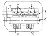
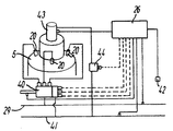
図1の実施形態においては、2−ストローク内燃機関1は、一列に配列された6個のシリンダ2を備えている(直列型エンジン)。このエンジンは、4個乃至15個のシリンダのような別の数のシリンダを備えることができる。このエンジンは、例えば、製造元がMAN B&W DieselのMC又はMEタイプ、製造元WartsilaのSulzer RT−flex又はSulzer RTAのタイプ、又は製造元Mitsubishiのものとすることができる。シリンダは、例えば25ないし120cm、好ましくは35乃至120cm、より好ましくは50乃至110cmの範囲内のボアを有することができる。このエンジンは、例えば、シリンダ当たり270乃至8500kW好ましくは1000乃至7000kWの範囲内の出力を有することができる。
Claims (13)
- クロスヘッド型の2−ストローク内燃機関におけるピストンリングの当該ピストンリングに関連するピストンに対する回転位置の強制的な変化を生じさせる方法であって、エンジンが所望の一定負荷又は所望の一定スピードで連続的に作動するように設定されている間に、シリンダ内でのピストンリングの回転位置の強制的な変化によって、前記シリンダ内の平均有効圧力が少なくとも0.5バールだけ変化するように少なくとも前記シリンダにかかる負荷を変化させ且つ前記変化せしめられた負荷を一定期間に亘って前記シリンダ内に維持することによってなされることを特徴とする方法。
- 請求項1に記載の方法であって、
前記ピストンリングの回転方向位置が監視され、前記ピストンリングの回転動作が検知されるまで前記変化せしめられた負荷が維持されることを特徴とする方法。 - 請求項1に記載の方法であって、
前記変化せしめられた負荷が、2乃至6分の範囲内の所定の期間に亘って維持されることを特徴とする方法。 - 請求項1乃至3のうちのいずれか一項に記載の方法であって、
前記シリンダ内の変化せしめられた負荷が負荷の増大であり、これと同時にエンジン内の別のシリンダにかかる負荷が前記負荷の増大に対応した負荷の減少であり、それによって、所望の一定のエンジン負荷が維持されるようになされることを特徴とする方法。 - 請求項1乃至4のうちのいずれか一項に記載の方法であって、
シリンダにかかる負荷を変化させることによってなされるシリンダ内のピストンリングの回転位置の強制的な変化が、エンジン内の全てのシリンダに適用されることを特徴とする方法。 - 請求項5に記載の方法であって、
シリンダ内のピストンリングの回転位置の強制的な変化が、エンジン内の全てのシリンダにかかる負荷を同時に変化させることによってなされることを特徴とする方法。 - 請求項5に記載の方法であって、
前記シリンダ内のピストンリングの回転位置の強制的な変化が、一回に単一のシリンダに、又は一回に2つのシリンダに同時に、又は一回に3つ以上のシリンダに同時になされて、全てのシリンダをカバーする連続的な方法で適用されることを特徴とする方法。 - 請求項1乃至7のうちのいずれか一項に記載の方法であって、
前記少なくとも1つのシリンダ内のピストンリングの回転位置の強制的な変化がときどき好ましくは前記所望の一定負荷又は前記所望の一定スピードでの4時間の作動当たり少なくとも1回繰り返されることを特徴とする方法。 - 請求項8に記載の方法であって、
前記少なくとも1つのシリンダ内のピストンリングの回転位置の強制的な変化が、前記所望の一定負荷又は前記所望の一定スピードでの1時間の作動毎に少なくとも1回繰り返されることを特徴とする方法。 - 請求項1乃至4のうちのいずれか一項に記載の方法であって、
前記ピストンリングの回転位置が少なくとも1つのシリンダ上で監視され、前記シリンダにかかる負荷を変化させることによるピストンリングの回転位置の強制的な変化が、前記監視によってシリンダ内のピストンリングの不十分な回転が指示されたときにシリンダに適用されることを特徴とする方法。 - 請求項1乃至10のうちのいずれか一項に記載の方法であって、
エンジンが船舶内の推進エンジンであり、前記エンジンは設定された平均速度で推進するように制御される間に、前記エンジンの負荷は、当該エンジンのシリンダ内の平均有効圧力が前記少なくとも0.5バールだけ変化せしめられるように、ときどき変化せしめられることを特徴とする方法。 - ピストンリングを備えたピストンと、エンジンの作動中における関連するピストンに対するピストンリングの回転位置の変化を監視するための少なくとも1つのセンサーとを備えている幾つかのシリンダを備えたクロスヘッド型の2−ストローク内燃機関であって、
シリンダ負荷制御ユニットが、リングの回転を確保するための所定の計画に従って且つ/又は不十分なピストンリングの回転を示す前記少なくとも1つのセンサーからの信号に応答して、前記シリンダ上に所定の一時的な負荷変化を生じさせることによって、少なくとも1つのシリンダ内のピストンリングの回転位置の変化を惹き起こすようになされていることを特徴とする2−ストローク内燃機関。 - 請求項12に記載の2−ストローク内燃機関であって、
前記シリンダ負荷制御ユニットは、前記一のシリンダにかかる所定の一時的な負荷変化が負荷の減少であるときに少なくとも1つの他のシリンダにかかる負荷を増大させ、前記一のシリンダにおける所定の一時的な負荷変化が負荷の増大であるときに前記少なくとも1つの他のシリンダの負荷を減少させることによって、エンジンの負荷を一定に保つことを特徴とする2−ストローク内燃機関。
Priority Applications (3)
| Application Number | Priority Date | Filing Date | Title |
|---|---|---|---|
| JP2006129103A JP4429294B2 (ja) | 2006-05-08 | 2006-05-08 | ピストンリングの回転位置の強制的な変化を生じさせる方法及びクロスヘッド型の2−ストローク内燃機関 |
| KR1020060059541A KR100808275B1 (ko) | 2006-05-08 | 2006-06-29 | 피스톤 링의 회전 위치의 강제 변화를 야기하는 방법 및 크로스헤드 타입의 2행정 내연 기관 엔진 |
| CN2006101000841A CN101070796B (zh) | 2006-05-08 | 2006-06-29 | 强制改变活塞环旋转位置的方法和十字头式二冲程内燃机 |
Applications Claiming Priority (1)
| Application Number | Priority Date | Filing Date | Title |
|---|---|---|---|
| JP2006129103A JP4429294B2 (ja) | 2006-05-08 | 2006-05-08 | ピストンリングの回転位置の強制的な変化を生じさせる方法及びクロスヘッド型の2−ストローク内燃機関 |
Publications (2)
| Publication Number | Publication Date |
|---|---|
| JP2007303476A true JP2007303476A (ja) | 2007-11-22 |
| JP4429294B2 JP4429294B2 (ja) | 2010-03-10 |
Family
ID=38837580
Family Applications (1)
| Application Number | Title | Priority Date | Filing Date |
|---|---|---|---|
| JP2006129103A Expired - Fee Related JP4429294B2 (ja) | 2006-05-08 | 2006-05-08 | ピストンリングの回転位置の強制的な変化を生じさせる方法及びクロスヘッド型の2−ストローク内燃機関 |
Country Status (3)
| Country | Link |
|---|---|
| JP (1) | JP4429294B2 (ja) |
| KR (1) | KR100808275B1 (ja) |
| CN (1) | CN101070796B (ja) |
Family Cites Families (6)
| Publication number | Priority date | Publication date | Assignee | Title |
|---|---|---|---|---|
| CH541070A (de) * | 1971-07-27 | 1973-08-31 | Sulzer Ag | Geschlitzter Kolbenring einer Kolbenbrennkraftmaschine |
| CH590416A5 (ja) * | 1975-04-17 | 1977-08-15 | Sulzer Ag | |
| US4379234A (en) * | 1981-05-15 | 1983-04-05 | Cummins Engine Company, Inc. | Electro optic controlled piston ring installing apparatus |
| DK172244B1 (da) * | 1994-05-27 | 1998-02-02 | Man B & W Diesel Gmbh | Opdelt udstødsreceiver i en stor jævntryksladet forbrændingsmotor |
| DK172961B1 (da) * | 1997-05-27 | 1999-10-18 | Man B & W Dielsel As | Hydraulisk centralenhed til en cylinder i en forbrændingsmotor |
| DE10222313C1 (de) | 2002-05-18 | 2003-11-27 | Man B & W Diesel As Kopenhagen | Kreuzkopfmotor |
-
2006
- 2006-05-08 JP JP2006129103A patent/JP4429294B2/ja not_active Expired - Fee Related
- 2006-06-29 CN CN2006101000841A patent/CN101070796B/zh not_active Expired - Fee Related
- 2006-06-29 KR KR1020060059541A patent/KR100808275B1/ko not_active Expired - Fee Related
Also Published As
| Publication number | Publication date |
|---|---|
| KR100808275B1 (ko) | 2008-02-29 |
| CN101070796B (zh) | 2011-06-01 |
| JP4429294B2 (ja) | 2010-03-10 |
| KR20070108802A (ko) | 2007-11-13 |
| CN101070796A (zh) | 2007-11-14 |
Similar Documents
| Publication | Publication Date | Title |
|---|---|---|
| DK2446123T3 (en) | Lubrication of cylinders in large diesel engines, particularly marine engines | |
| JP6226837B2 (ja) | 大型低速2ストロークディーゼル機関用のシリンダ潤滑デバイスおよびシリンダ潤滑システムの運転方法 | |
| JP6193291B2 (ja) | 燃料供給装置 | |
| CN101415936B (zh) | 十字头型的大型单流式双冲程柴油发动机 | |
| DK179118B1 (en) | Cylinder lubrication apparatus for a large two-stroke compression-ignited internal combustion engine | |
| JP6574440B2 (ja) | シリンダに潤滑油を注油する方法及びシステム | |
| WO2010054653A1 (en) | Large two-stroke diesel engine with electronically controlled exhaust valve actuation system | |
| WO2010006599A1 (en) | Cam driven exhaust valve actuation system for large two stroke diesel engine | |
| JP5762495B2 (ja) | クロスヘッドおよびカム駆動式排気弁作動システムを有する大型低速ターボ過給式2ストロークユニフロー内燃機関 | |
| KR101278423B1 (ko) | 대형 디젤엔진의 실린더 표면을 윤활하는 방법 및 장치 | |
| CN103244302B (zh) | 包括汽缸润滑装置的大型发动机和用于润滑其汽缸的方法 | |
| KR102203587B1 (ko) | 내연 기관의 작동 | |
| JP4429294B2 (ja) | ピストンリングの回転位置の強制的な変化を生じさせる方法及びクロスヘッド型の2−ストローク内燃機関 | |
| JP5746727B2 (ja) | シリンダ潤滑デバイス | |
| JP4597264B2 (ja) | クロスヘッド型大型ユニフロー式2サイクルディーゼル機関 | |
| US20010040346A1 (en) | Piston ring assembly | |
| CN102251895B (zh) | 十字头型的大型单流式双冲程柴油发动机 |
Legal Events
| Date | Code | Title | Description |
|---|---|---|---|
| A131 | Notification of reasons for refusal |
Free format text: JAPANESE INTERMEDIATE CODE: A131 Effective date: 20080125 |
|
| A601 | Written request for extension of time |
Free format text: JAPANESE INTERMEDIATE CODE: A601 Effective date: 20080424 |
|
| A602 | Written permission of extension of time |
Free format text: JAPANESE INTERMEDIATE CODE: A602 Effective date: 20080430 |
|
| A521 | Written amendment |
Free format text: JAPANESE INTERMEDIATE CODE: A523 Effective date: 20080714 |
|
| A02 | Decision of refusal |
Free format text: JAPANESE INTERMEDIATE CODE: A02 Effective date: 20081112 |
|
| A521 | Written amendment |
Free format text: JAPANESE INTERMEDIATE CODE: A523 Effective date: 20090310 |
|
| A911 | Transfer to examiner for re-examination before appeal (zenchi) |
Free format text: JAPANESE INTERMEDIATE CODE: A911 Effective date: 20090414 |
|
| A912 | Re-examination (zenchi) completed and case transferred to appeal board |
Free format text: JAPANESE INTERMEDIATE CODE: A912 Effective date: 20090508 |
|
| A01 | Written decision to grant a patent or to grant a registration (utility model) |
Free format text: JAPANESE INTERMEDIATE CODE: A01 |
|
| A61 | First payment of annual fees (during grant procedure) |
Free format text: JAPANESE INTERMEDIATE CODE: A61 Effective date: 20091215 |
|
| FPAY | Renewal fee payment (event date is renewal date of database) |
Free format text: PAYMENT UNTIL: 20121225 Year of fee payment: 3 |
|
| R150 | Certificate of patent or registration of utility model |
Ref document number: 4429294 Country of ref document: JP Free format text: JAPANESE INTERMEDIATE CODE: R150 Free format text: JAPANESE INTERMEDIATE CODE: R150 |
|
| FPAY | Renewal fee payment (event date is renewal date of database) |
Free format text: PAYMENT UNTIL: 20131225 Year of fee payment: 4 |
|
| R250 | Receipt of annual fees |
Free format text: JAPANESE INTERMEDIATE CODE: R250 |
|
| R250 | Receipt of annual fees |
Free format text: JAPANESE INTERMEDIATE CODE: R250 |
|
| R250 | Receipt of annual fees |
Free format text: JAPANESE INTERMEDIATE CODE: R250 |
|
| R250 | Receipt of annual fees |
Free format text: JAPANESE INTERMEDIATE CODE: R250 |
|
| R250 | Receipt of annual fees |
Free format text: JAPANESE INTERMEDIATE CODE: R250 |
|
| R250 | Receipt of annual fees |
Free format text: JAPANESE INTERMEDIATE CODE: R250 |
|
| R250 | Receipt of annual fees |
Free format text: JAPANESE INTERMEDIATE CODE: R250 |
|
| R250 | Receipt of annual fees |
Free format text: JAPANESE INTERMEDIATE CODE: R250 |
|
| LAPS | Cancellation because of no payment of annual fees |