JP2007303620A - Under seal of linear guide device and linear guide device having the same - Google Patents
Under seal of linear guide device and linear guide device having the same Download PDFInfo
- Publication number
- JP2007303620A JP2007303620A JP2006134762A JP2006134762A JP2007303620A JP 2007303620 A JP2007303620 A JP 2007303620A JP 2006134762 A JP2006134762 A JP 2006134762A JP 2006134762 A JP2006134762 A JP 2006134762A JP 2007303620 A JP2007303620 A JP 2007303620A
- Authority
- JP
- Japan
- Prior art keywords
- under seal
- linear guide
- guide device
- guide rail
- bearing block
- Prior art date
- Legal status (The legal status is an assumption and is not a legal conclusion. Google has not performed a legal analysis and makes no representation as to the accuracy of the status listed.)
- Granted
Links
Images


Classifications
-
- F—MECHANICAL ENGINEERING; LIGHTING; HEATING; WEAPONS; BLASTING
- F16—ENGINEERING ELEMENTS AND UNITS; GENERAL MEASURES FOR PRODUCING AND MAINTAINING EFFECTIVE FUNCTIONING OF MACHINES OR INSTALLATIONS; THERMAL INSULATION IN GENERAL
- F16C—SHAFTS; FLEXIBLE SHAFTS; ELEMENTS OR CRANKSHAFT MECHANISMS; ROTARY BODIES OTHER THAN GEARING ELEMENTS; BEARINGS
- F16C29/00—Bearings for parts moving only linearly
- F16C29/08—Arrangements for covering or protecting the ways
- F16C29/084—Arrangements for covering or protecting the ways fixed to the carriage or bearing body movable along the guide rail or track
- F16C29/088—Seals extending in the longitudinal direction of the carriage or bearing body
-
- F—MECHANICAL ENGINEERING; LIGHTING; HEATING; WEAPONS; BLASTING
- F16—ENGINEERING ELEMENTS AND UNITS; GENERAL MEASURES FOR PRODUCING AND MAINTAINING EFFECTIVE FUNCTIONING OF MACHINES OR INSTALLATIONS; THERMAL INSULATION IN GENERAL
- F16C—SHAFTS; FLEXIBLE SHAFTS; ELEMENTS OR CRANKSHAFT MECHANISMS; ROTARY BODIES OTHER THAN GEARING ELEMENTS; BEARINGS
- F16C29/00—Bearings for parts moving only linearly
- F16C29/04—Ball or roller bearings
- F16C29/06—Ball or roller bearings in which the rolling bodies circulate partly without carrying load
- F16C29/0633—Ball or roller bearings in which the rolling bodies circulate partly without carrying load with a bearing body defining a U-shaped carriage, i.e. surrounding a guide rail or track on three sides
- F16C29/0635—Ball or roller bearings in which the rolling bodies circulate partly without carrying load with a bearing body defining a U-shaped carriage, i.e. surrounding a guide rail or track on three sides whereby the return paths are provided as bores in a main body of the U-shaped carriage, e.g. the main body of the U-shaped carriage is a single part with end caps provided at each end
- F16C29/0638—Ball or roller bearings in which the rolling bodies circulate partly without carrying load with a bearing body defining a U-shaped carriage, i.e. surrounding a guide rail or track on three sides whereby the return paths are provided as bores in a main body of the U-shaped carriage, e.g. the main body of the U-shaped carriage is a single part with end caps provided at each end with balls
- F16C29/0642—Ball or roller bearings in which the rolling bodies circulate partly without carrying load with a bearing body defining a U-shaped carriage, i.e. surrounding a guide rail or track on three sides whereby the return paths are provided as bores in a main body of the U-shaped carriage, e.g. the main body of the U-shaped carriage is a single part with end caps provided at each end with balls with four rows of balls
-
- F—MECHANICAL ENGINEERING; LIGHTING; HEATING; WEAPONS; BLASTING
- F16—ENGINEERING ELEMENTS AND UNITS; GENERAL MEASURES FOR PRODUCING AND MAINTAINING EFFECTIVE FUNCTIONING OF MACHINES OR INSTALLATIONS; THERMAL INSULATION IN GENERAL
- F16C—SHAFTS; FLEXIBLE SHAFTS; ELEMENTS OR CRANKSHAFT MECHANISMS; ROTARY BODIES OTHER THAN GEARING ELEMENTS; BEARINGS
- F16C43/00—Assembling bearings
- F16C43/04—Assembling rolling-contact bearings
- F16C43/045—Mounting or replacing seals
Landscapes
- Engineering & Computer Science (AREA)
- General Engineering & Computer Science (AREA)
- Mechanical Engineering (AREA)
- Bearings For Parts Moving Linearly (AREA)
Abstract
【課題】簡単かつ安価な構成でありながら、簡単に組み付け・交換等をすることができるリニアガイド装置のアンダーシールを提供する。
【解決手段】本発明に係るアンダーシール2は、エラストマやプラスチックス等の樹脂材料のみで構成される。アンダーシール2は、リップ部2Aをガイドレール20に当接して所望のシール性を確保するのに十分な強度(剛性)を備える一方で、エンドキャップ3に設けられるアンダーシール溝3Aに、差込部分2a、2bを差し込む際に撓ませることができる程度の弾性を備えて構成される。これにより、従来のアンダーシールのようにゴム等の弾性材料に芯金を装填して構成されたものに対して、所望のシール性を確保しながら、ベアリングブロックをガイドレールに組み付けた状態であっても、簡単かつ迅速にアンダーシールの組み付け・交換等を行なうことができる。
【選択図】図3
An underseal of a linear guide device that can be easily assembled and replaced while having a simple and inexpensive configuration.
An under seal 2 according to the present invention is composed only of a resin material such as an elastomer or plastics. The under seal 2 has sufficient strength (rigidity) to secure the desired sealing performance by bringing the lip portion 2A into contact with the guide rail 20, while being inserted into the under seal groove 3A provided in the end cap 3. It is configured to be elastic enough to bend when the portions 2a and 2b are inserted. As a result, the bearing block is assembled to the guide rail while ensuring the desired sealing performance, compared to a conventional underseal that is constructed by loading a core metal with an elastic material such as rubber. However, it is possible to easily and quickly assemble and replace the under seal.
[Selection] Figure 3
Description
本発明は、リニアガイド装置のアンダーシール及びこれを備えたリニアガイド装置に関する。 The present invention relates to an under seal of a linear guide device and a linear guide device including the same.
一般に、リニアガイド(直動案内)装置10は、図7に示すように、ガイドレール20と、ベアリングブロック30と、ガイドレール20に設けられるレール側転動溝21とベアリングブロック30に設けられるベアリングブロック側転動溝31との間に転動自在に介装される転動体(ボール)40と、を含んで構成される。
In general, as shown in FIG. 7, the linear guide (linear guide)
そして、この種のリニアガイド装置10には、図7に示したように、ガイドレール20の中心軸を挟んで両側にボール列が配設されており、転動体(ボール)40は、ガイドレール側ボール溝21及びベアリングブロック側ボール溝31、エンドキャップ50に設けられる方向転換路51、ベアリングブロック30に設けられる循環路32を通って、無限循環するように構成されている。
In this type of
ここで、特許文献1に開示されるように、図7のリニアガイド装置10には、油密の確保や異物の混入等を抑制するために、ガイドレール20とベアリングブロック30との間に、アンダーシール60が設けられる。該アンダーシール60は、その両端部がエンドキャップ50に設けられるアンダーシール溝52(図8参照)にそれぞれ挿入されて保持される。
Here, as disclosed in Patent Document 1, the
アンダーシール60を、アンダーシール溝52に挿入するには、アンダーシール60はその全長に亘ってシール性能を確保できるようにゴム等の弾性材料に芯金を装填して構成されているため長手方向における剛性が高いことから、ガイドレール20側(図8に示す矢印Y方向)からアンダーシール60を挿入する必要がある。このため、従来のリニアガイド装置10においては、ベアリングブロック30がガイドレール20に組み付けられている状態では、アンダーシール60をアンダーシール溝52に挿入することはできなかった。同様に、ベアリングブロック30がガイドレール20に組み付けられている状態では、アンダーシール60をアンダーシール溝52から外すことはできなかった。
In order to insert the under
従って、従来においては、アンダーシール60を損傷、劣化等により交換しようとする場合、ベアリングブロック30をガイドレール20から取り外さなければならなかった。例えば、一本のレールに複数のベアリングブロックを取り付けている場合などにおいては、1個のベアリングブロックのアンダーシールだけを交換したい場合でも、該当するベアリングブロック以外のベアリングブロックも一旦ガイドレールから外さなければならない場合もあり、多大な時間と手間を要するおそれがある。
本発明は、上記従来の実情に鑑みなされたもので、簡単かつ安価な構成でありながら、簡単に組み付け・交換等をすることができるリニアガイド装置のアンダーシール及び該アンダーシールを利用したリニアガイド装置を提供することを目的とする。 The present invention has been made in view of the above-described conventional situation, and has an underseal of a linear guide device that can be easily assembled and replaced while having a simple and inexpensive configuration, and a linear guide using the underseal. An object is to provide an apparatus.
上記の目的を達成するため、請求項1に記載の発明に係るリニアガイド装置のアンダーシールでは、
ガイドレールと、転動体を介してガイドレールに移動自在に配設されるベアリングブロックと、ベアリングブロックの両端に配設されるエンドキャップと、を含んで構成されるリニアガイド装置のアンダーシールであって、各端部が対応するエンドキャップに設けられるアンダーシール溝にそれぞれ挿入保持されて、ガイドレールとベアリングブロックとの間のシールを行なうものにおいて、
当該アンダーシールを、ベアリングブロックがガイドレールに取り付けられた状態において、前記アンダーシール溝から取り外すことができると共に前記アンダーシール溝へ取り付けることができる弾性材料のみで構成した。
In order to achieve the above object, in the under seal of the linear guide device according to the invention of claim 1,
An under seal of a linear guide device including a guide rail, a bearing block that is movably disposed on the guide rail via a rolling element, and end caps that are disposed at both ends of the bearing block. Each end is inserted and held in an under seal groove provided in the corresponding end cap, and seals between the guide rail and the bearing block.
The under seal was made of only an elastic material that can be removed from the under seal groove and attached to the under seal groove in a state where the bearing block is attached to the guide rail.
請求項2に記載の発明は、前記弾性材料が、エラストマ若しくはプラスチックス等の樹脂材料であることを特徴とする。
The invention described in
請求項3に記載の発明に係るリニアガイド装置は、請求項1又は請求項2に記載のリニアガイド装置のアンダーシールを含んで構成した。 A linear guide device according to a third aspect of the invention includes the under seal of the linear guide device according to the first or second aspect.
本発明は、従来のアンダーシールのようにゴム等の弾性材料に芯金を装填して構成されたものに対して、アンダーシールをエラストマやプラスチックス等の樹脂材料のみで構成したので、所望のシール性を確保しながら、ベアリングブロックをガイドレールに組み付けた状態であっても、アンダーシールを、エンドキャップに設けられるアンダーシール溝に簡単かつ迅速に挿入して取り付けることができる或いは取り外すことができるため、簡単かつ迅速にアンダーシールの組み付け・交換等を行なうことができる。 In the present invention, since the under seal is composed only of a resin material such as elastomer or plastic, in contrast to the conventional under seal configured by loading a core metal on an elastic material such as rubber, a desired material can be obtained. Even when the bearing block is assembled to the guide rail while ensuring the sealing performance, the under seal can be easily and quickly inserted into and removed from the under seal groove provided in the end cap. Therefore, it is possible to easily and quickly assemble / replace the under seal.
従って、本発明によれば、簡単かつ安価な構成でありながら、簡単に組み付け・交換等をすることができるリニアガイド装置のアンダーシール及び該アンダーシールを利用したリニアガイド装置を提供することができる。 Therefore, according to the present invention, it is possible to provide an under seal of a linear guide device that can be easily assembled and replaced while having a simple and inexpensive configuration, and a linear guide device using the under seal. .
以下、添付の図面を参照しつつ、本発明の一実施の形態について詳細に説明する。
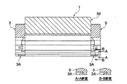
本発明の一実施の形態に係るリニアガイド装置1は、本実施形態で用いるアンダーシール2を除き、図7で示したものとほぼ同様の構成であるため、同様の構成要素には同一の符号を付すこととして、その詳細な説明は省略する。
Hereinafter, an embodiment of the present invention will be described in detail with reference to the accompanying drawings.
Since the linear guide device 1 according to the embodiment of the present invention has substantially the same configuration as that shown in FIG. 7 except for the
図1に示す本実施形態に係るリニアガイド装置1では、図2に示すような、ガイドレール20に当接されるリップ部2Aと、その両端部がアンダーシール溝3Aに挿入されて保持される保持部2Bと、を含んで構成されるアンダーシール2を用いる。該アンダーシール2は、エラストマやプラスチックス等の樹脂材料のみで構成されている。
In the linear guide device 1 according to the present embodiment shown in FIG. 1, a
アンダーシール2は、リップ部2Aをガイドレール20に当接して所望のシール性を確保するのに十分な強度(剛性)を備える一方で、図3(A)、図3(B)に示すような方法でエンドキャップ3に設けられるアンダーシール溝3Aに、後述する差込部分2a、2bを差し込む際に撓ませることができる程度の弾性を備えて構成される。
As shown in FIGS. 3A and 3B, the
なお、アンダーシール2は、上記の強度(剛性)及び弾性に関する要求特性を備えることができれば、他の材料で構成されても良い。
The
ここで、本実施形態におけるアンダーシール2のベアリングブロック30への取り付け方法について、図3(A)、図3(B)を参照しつつ説明する。
Here, the attachment method to the
まず、ガイドレール20に組み付けられた状態のベアリングブロック30にアンダーシール2を取り付ける際には、アンダーシール2の一端にある差込部分2aを、エンドキャップ3に隣接するベアリングブロック30側(図3(A)の矢印方向)から、対応する側のアンダーシール溝3Aに挿入する。
First, when the
次に、アンダーシール2を、図3(B)に示すように下方に撓ませて、アンダーシール2の他端にある差込部分2bを、エンドキャップ3に隣接するベアリングブロック30側(図3(B)の矢印方向)から、対応する側のアンダーシール溝3Aに挿入する。
Next, the
ガイドレール20に組み付けられた状態のベアリングブロック30からアンダーシール2を取り外す際は、アンダーシール2を、図3(B)に示すように下方に撓ませて、エンドキャップ3のアンダーシール溝3Aからアンダーシール2の差込部分2a、2bを抜き取る。
When the
このように、本実施形態によれば、従来のアンダーシールのようにゴム等の弾性材料に芯金を装填して構成されるものに対して、アンダーシール2をエラストマやプラスチックス等の樹脂材料のみで構成したので、所望のシール性を確保することができると共に、ベアリングブロック30をガイドレール20に組み付けた状態であっても、アンダーシール2の差込部分2a、2bを、対応する側のアンダーシール溝3Aに簡単かつ迅速に挿入或いは取り外することができるため、簡単かつ迅速にアンダーシールの組み付け・交換等を行なうことができる。
As described above, according to the present embodiment, the
なお、アンダーシール2の端面を、図4に示すような形状とすることもでき、かかる場合には、アンダーシール溝3Aは、図5に示すような形状とすることができる。
Note that the end face of the under
更に、アンダーシール2の保持部2Bに、図6(A)、図6(B)に示すように、突起2Cを設ける一方、該突起2Cと係合可能な凹部(図示せず)をアンダーシール溝3Aに設け、アンダーシール2の脱落防止などを一層確実なものとするように構成することもできる。
Further, as shown in FIGS. 6A and 6B, the
ところで、アンダーシール2、アンダーシール溝3Aの形状は、本実施形態で例示したものに限定されるものではなく、組み付け・交換容易で、所定にシール性を確保しつつ保持可能な形状であれば、他の形状とすることができることは勿論である。
By the way, the shapes of the under
1 リニアガイド装置
2 アンダーシール
3 エンドキャップ
3A アンダーシール溝
20 ガイドレール
30 ベアリングブロック
40 転動体(ボール)
DESCRIPTION OF SYMBOLS 1
Claims (3)
当該アンダーシールが、ベアリングブロックがガイドレールに組み付けられた状態において、前記アンダーシール溝から取り外すことができると共に前記アンダーシール溝へ取り付けることができる弾性材料のみで構成されたことを特徴とするリニアガイド装置のアンダーシール。 An under seal of a linear guide device including a guide rail, a bearing block that is movably disposed on the guide rail via a rolling element, and end caps that are disposed at both ends of the bearing block. Each end is inserted and held in an under seal groove provided in the corresponding end cap, and seals between the guide rail and the bearing block.
The linear guide is composed of only an elastic material that can be removed from the under seal groove and attached to the under seal groove in a state where the bearing block is assembled to the guide rail. Equipment under seal.
A linear guide device comprising the under seal of the linear guide device according to claim 1 or 2.
Priority Applications (1)
| Application Number | Priority Date | Filing Date | Title |
|---|---|---|---|
| JP2006134762A JP4688066B2 (en) | 2006-05-15 | 2006-05-15 | Linear guide device |
Applications Claiming Priority (1)
| Application Number | Priority Date | Filing Date | Title |
|---|---|---|---|
| JP2006134762A JP4688066B2 (en) | 2006-05-15 | 2006-05-15 | Linear guide device |
Publications (2)
| Publication Number | Publication Date |
|---|---|
| JP2007303620A true JP2007303620A (en) | 2007-11-22 |
| JP4688066B2 JP4688066B2 (en) | 2011-05-25 |
Family
ID=38837715
Family Applications (1)
| Application Number | Title | Priority Date | Filing Date |
|---|---|---|---|
| JP2006134762A Expired - Fee Related JP4688066B2 (en) | 2006-05-15 | 2006-05-15 | Linear guide device |
Country Status (1)
| Country | Link |
|---|---|
| JP (1) | JP4688066B2 (en) |
Cited By (3)
| Publication number | Priority date | Publication date | Assignee | Title |
|---|---|---|---|---|
| JP2013092203A (en) * | 2011-10-26 | 2013-05-16 | Nsk Ltd | Underseal, and linear guide device |
| JP2013167352A (en) * | 2011-12-27 | 2013-08-29 | Nsk Ltd | Rectilinear guide device |
| CN105229319A (en) * | 2013-05-21 | 2016-01-06 | 舍弗勒技术股份两合公司 | Guide carriage for linear guides |
Citations (2)
| Publication number | Priority date | Publication date | Assignee | Title |
|---|---|---|---|---|
| JPH0398320U (en) * | 1990-01-26 | 1991-10-11 | ||
| JPH0419918U (en) * | 1990-06-12 | 1992-02-19 |
-
2006
- 2006-05-15 JP JP2006134762A patent/JP4688066B2/en not_active Expired - Fee Related
Patent Citations (2)
| Publication number | Priority date | Publication date | Assignee | Title |
|---|---|---|---|---|
| JPH0398320U (en) * | 1990-01-26 | 1991-10-11 | ||
| JPH0419918U (en) * | 1990-06-12 | 1992-02-19 |
Cited By (4)
| Publication number | Priority date | Publication date | Assignee | Title |
|---|---|---|---|---|
| JP2013092203A (en) * | 2011-10-26 | 2013-05-16 | Nsk Ltd | Underseal, and linear guide device |
| JP2013167352A (en) * | 2011-12-27 | 2013-08-29 | Nsk Ltd | Rectilinear guide device |
| CN105229319A (en) * | 2013-05-21 | 2016-01-06 | 舍弗勒技术股份两合公司 | Guide carriage for linear guides |
| CN105229319B (en) * | 2013-05-21 | 2017-10-13 | 舍弗勒技术股份两合公司 | Guide carriage for linear guides |
Also Published As
| Publication number | Publication date |
|---|---|
| JP4688066B2 (en) | 2011-05-25 |
Similar Documents
| Publication | Publication Date | Title |
|---|---|---|
| EP2607730B1 (en) | Linear guide device | |
| JP2931465B2 (en) | Linear motion rolling guide unit | |
| JP5408346B2 (en) | Linear motion guide device | |
| CN103732930A (en) | Guide device | |
| US5358336A (en) | Linear motion rolling guide unit | |
| US20090310892A1 (en) | Linear motion guide apparatus having changeable sealing structure | |
| JP4688066B2 (en) | Linear guide device | |
| JP2005291341A (en) | Linear motion guide bearing device and under seal | |
| JP5120239B2 (en) | Linear motion device | |
| US5324116A (en) | Linear motion rolling guide unit | |
| JP6146009B2 (en) | Linear motion guide device | |
| CN100467207C (en) | Rolling element containment belts and linear guides for linear guides | |
| JP4635758B2 (en) | Stopper device and linear guide device having the same | |
| JP5866966B2 (en) | Under seal and linear guide device | |
| JP4622971B2 (en) | Linear motion guide device | |
| CN110388382B (en) | Miniature linear sliding rail and sliding seat thereof | |
| JP5223714B2 (en) | Linear motion guide device | |
| JP2013177969A (en) | Linear guide device | |
| JP6311449B2 (en) | Linear motion guide device | |
| JP2008128384A (en) | Rolling body holder and linear motion guide device having the same | |
| JP2018003897A (en) | Linear guide device | |
| JP2007132445A (en) | Linear guide device | |
| JP7079173B2 (en) | Exercise guidance device | |
| JP2006064007A (en) | Linear motion guide device | |
| JP2015117785A (en) | Under seal and linear guide device |
Legal Events
| Date | Code | Title | Description |
|---|---|---|---|
| A621 | Written request for application examination |
Free format text: JAPANESE INTERMEDIATE CODE: A621 Effective date: 20090220 |
|
| A977 | Report on retrieval |
Free format text: JAPANESE INTERMEDIATE CODE: A971007 Effective date: 20100527 |
|
| A131 | Notification of reasons for refusal |
Free format text: JAPANESE INTERMEDIATE CODE: A131 Effective date: 20100602 |
|
| A521 | Written amendment |
Free format text: JAPANESE INTERMEDIATE CODE: A523 Effective date: 20100730 |
|
| TRDD | Decision of grant or rejection written | ||
| A01 | Written decision to grant a patent or to grant a registration (utility model) |
Free format text: JAPANESE INTERMEDIATE CODE: A01 Effective date: 20110124 |
|
| A01 | Written decision to grant a patent or to grant a registration (utility model) |
Free format text: JAPANESE INTERMEDIATE CODE: A01 |
|
| R150 | Certificate of patent or registration of utility model |
Ref document number: 4688066 Country of ref document: JP Free format text: JAPANESE INTERMEDIATE CODE: R150 Free format text: JAPANESE INTERMEDIATE CODE: R150 |
|
| A61 | First payment of annual fees (during grant procedure) |
Free format text: JAPANESE INTERMEDIATE CODE: A61 Effective date: 20110206 |
|
| FPAY | Renewal fee payment (event date is renewal date of database) |
Free format text: PAYMENT UNTIL: 20140225 Year of fee payment: 3 |
|
| LAPS | Cancellation because of no payment of annual fees |