JP2007315744A - Scooter type motorcycle - Google Patents
Scooter type motorcycle Download PDFInfo
- Publication number
- JP2007315744A JP2007315744A JP2007175591A JP2007175591A JP2007315744A JP 2007315744 A JP2007315744 A JP 2007315744A JP 2007175591 A JP2007175591 A JP 2007175591A JP 2007175591 A JP2007175591 A JP 2007175591A JP 2007315744 A JP2007315744 A JP 2007315744A
- Authority
- JP
- Japan
- Prior art keywords
- cover
- fins
- cooling air
- fin
- air intake
- Prior art date
- Legal status (The legal status is an assumption and is not a legal conclusion. Google has not performed a legal analysis and makes no representation as to the accuracy of the status listed.)
- Granted
Links
Images



Landscapes
- Air-Flow Control Members (AREA)
Abstract
【課題】被冷却物を覆うカバーに設けられるルーバーにおいて、カバー内への異物の侵入を効果的に防止した上で、カバー内に冷却空気を円滑に導入し得るようにする。
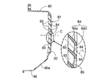
【解決手段】被冷却物に向けて開口した冷却空気取入口82を有して前記被冷却物を覆うカバー80に、前記冷却空気取入口82を複数の空気流通路83に分割する複数のフィン84が、各空気流通路83の外端中心および内端中心間を結ぶ直線Lを前記冷却空気取入口82の中心線Cに対して傾斜させる配置で設けられて成る、カバーのルーバーであって、前記各フィン84が、それらのフィン84の外端相互の間隔を各フィン84の内端相互の間隔よりも狭くした形状に形成される。
【選択図】図7In a louver provided on a cover that covers an object to be cooled, it is possible to smoothly introduce cooling air into the cover while effectively preventing foreign matter from entering the cover.
A cover having a cooling air intake opening that opens toward an object to be cooled and covering the object to be cooled has a plurality of fins that divide the cooling air intake into a plurality of air flow passages. 84 is a cover louver provided in such a manner that a straight line L connecting the outer end center and the inner end center of each air flow passage 83 is inclined with respect to the center line C of the cooling air intake 82. The fins 84 are formed in a shape in which the distance between the outer ends of the fins 84 is narrower than the distance between the inner ends of the fins 84.
[Selection] Figure 7
Description
本発明は、被冷却物を覆うカバーに設けられるルーバー、ならびに該ルーバーを有する合成樹脂製のカバーを成形するための金型装置の改良に関する。 The present invention relates to a louver provided on a cover that covers an object to be cooled, and an improvement of a mold apparatus for molding a synthetic resin cover having the louver.
従来、自動二輪車に搭載されたエンジンの放熱部を覆うカバーにルーバーが設けられたものが、特許文献1で開示されている。
ルーバーは、カバー内に導入する冷却空気の整流、カバー内で発生する騒音の外部への洩れ抑制、ならびにカバー内への異物の侵入防止を図るものであり、そのような効果を得るために、上記従来のルーバーでは、冷却空気取入口内に配置される複数のフィンが、それらのフィン相互間に形成される空気流通路の流通方向に沿って一直線状に傾斜してカバーに設けられている。 The louver is intended to rectify the cooling air introduced into the cover, to suppress the leakage of noise generated in the cover to the outside, and to prevent foreign matter from entering the cover. In the above-described conventional louver, a plurality of fins arranged in the cooling air intake port are provided on the cover so as to incline in a straight line along the flow direction of the air flow passage formed between the fins. .
ところで、カバー内への異物の侵入を効果的に防止するには各フィンの外端相互の間隔が狭いほうがよく、上記従来のルーバーで各フィンの外端相互の間隔を狭くすると、各フィン相互間の空気流通路の流通面積が流通方向全長にわたって小さくなり、空気流通路を流通する冷却空気の流通抵抗が大きくなってしまう。 By the way, in order to effectively prevent the entry of foreign matter into the cover, it is better that the distance between the outer ends of the fins is narrower. When the distance between the outer ends of the fins is reduced with the conventional louver, The flow area of the air flow passage in between is reduced over the entire length in the flow direction, and the flow resistance of the cooling air flowing through the air flow passage is increased.
本発明は、かかる事情に鑑みてなされたものであり、カバー内への異物の侵入を効果的に防止した上で、カバー内に冷却空気を円滑に導入し得るようにしたカバーのルーバーを提供することを目的とする。 The present invention has been made in view of such circumstances, and provides a louver for a cover that can effectively introduce cooling air into the cover while effectively preventing foreign matter from entering the cover. The purpose is to do.
上記目的を達成するために、請求項1記載の発明は、被冷却物に向けて開口した冷却空気取入口を有して前記被冷却物を覆うカバーに、前記冷却空気取入口を複数の空気流通路に分割する複数のフィンが、各空気流通路の外端中心および内端中心間を結ぶ直線を前記冷却空気取入口の中心線に対して傾斜させる配置で設けられて成る、カバーのルーバーであって、前記各フィンが、それらのフィンの外端相互の間隔を各フィンの内端相互の間隔よりも狭くした形状に形成されることを特徴とする。 In order to achieve the above object, the invention according to claim 1 is characterized in that a cooling air intake opening that opens toward the object to be cooled is provided on the cover that covers the object to be cooled. A louver for a cover, wherein a plurality of fins divided into flow passages are arranged so as to incline a straight line connecting between the outer end center and the inner end center of each air flow passage with respect to the center line of the cooling air intake port And each said fin is formed in the shape which made the space | interval of the outer ends of those fins narrower than the space | interval of the inner ends of each fin.
このような構成によれば、各フィンの外端相互の間隔を比較的狭く設定することで、カバー内への異物の侵入を効果的に防止することができる。しかも各フィンの内端相互の間隔は比較的広いので、各フィン相互間の空気流通路の流通面積は、各フィンの外端側の一部で小さくなるものの、空気流通路の全長にわたって小さくなることはなく、各空気流通路を流通する冷却空気の流通抵抗が大幅に増大することを避けて、冷却空気を各空気流通路で整流しつつカバー内に円滑に導入することができる。 According to such a structure, the penetration | invasion of the foreign material into a cover can be effectively prevented by setting the space | interval of the outer ends of each fin comparatively narrowly. In addition, since the distance between the inner ends of the fins is relatively wide, the flow area of the air flow passage between the fins is reduced at a part of the outer end side of each fin, but is reduced over the entire length of the air flow passage. In other words, it is possible to smoothly introduce the cooling air into the cover while rectifying the air in each air flow passage while avoiding a significant increase in the flow resistance of the cooling air flowing through each air flow passage.
また請求項2記載の発明は、上記請求項1記載の発明の構成に加えて、合成樹脂から成る前記カバーに一体に設けられる前記フィンが、前記冷却空気取入口の中心線に対して傾斜して延びるとともに前記冷却空気取入口の外端周縁部に外端を面一に連ならせるフィン主部と、該フィン主部の外端に鈍角をなして面一に連設されて隣接のフィン側に張出す張出部とから成ることを特徴とし、かかる構成によれば、フィンの外端側の肉厚を部分的に厚くするだけで、上記請求項1に記載したフィンの形状を得ることができ、フィンすなわちカバーの重量が大きく増大することを回避することができる。 According to a second aspect of the invention, in addition to the configuration of the first aspect of the invention, the fin integrally provided on the cover made of synthetic resin is inclined with respect to the center line of the cooling air intake. A fin main portion that extends to the outer peripheral edge of the cooling air inlet and is flush with the outer end of the fin main portion, and is adjacent to the fin. In this configuration, the fin shape according to claim 1 can be obtained simply by partially increasing the thickness of the outer end side of the fin. And a significant increase in the weight of the fin or cover can be avoided.
さらに請求項3記載の発明は、請求項2記載のルーバーを有するカバーを成形するためのカバー成形用金型装置であって、前記フィン主部の外側面および外端面ならびに前記張出部の外面および先端面を形成する第1成形部を有する第1金型と、前記フィン主部の内側面および内端面ならびに前記張出部の内面を形成する第2成形部を有する第2金型とを備えることを特徴とし、かかる金型装置によれば、第1および第2金型の型割り面を、フィンの外端位置よりも内方側に設定するようにして、フィンの外端部にバリやシャープジエッジが生じることを防止してカバーの外観性を高め、商品性を向上することができる。また第2金型が有する第2成形部の先端で張出部の内面を形成するようにして、第1および第2成形部の先端幅を確保しつつフィン相互の間隔を狭めることができ、これによってもカバーの商品性を向上することができる。 Furthermore, a third aspect of the present invention is a cover molding mold apparatus for molding a cover having the louver according to the second aspect, wherein the outer surface and the outer end surface of the fin main portion and the outer surface of the overhang portion. And a first mold having a first molding part that forms a tip surface, and a second mold having a second molding part that forms an inner surface and an inner end surface of the fin main part and an inner surface of the overhanging part. According to such a mold apparatus, the mold dividing surfaces of the first and second molds are set on the inner side of the outer end position of the fin, so that the outer end portion of the fin The appearance of the cover can be improved by preventing the occurrence of burrs and sharp edges, and the product quality can be improved. In addition, by forming the inner surface of the overhang portion at the tip of the second molding portion of the second mold, the gap between the fins can be reduced while ensuring the tip width of the first and second molding portions, Also by this, the merchantability of the cover can be improved.
以上のように請求項1記載の発明によれば、カバー内への異物の侵入を効果的に防止することができる上に、各空気流通路を流通する冷却空気の流通抵抗が大幅に増大することを避けて、冷却空気を各空気流通路で整流しつつカバー内に円滑に導入することができる。 As described above, according to the first aspect of the present invention, it is possible to effectively prevent foreign matter from entering the cover, and the flow resistance of the cooling air flowing through each air flow passage is greatly increased. By avoiding this, the cooling air can be smoothly introduced into the cover while being rectified in each air flow passage.
また請求項2記載の発明によれば、フィンの外端側の肉厚を部分的に厚くするだけで、上記請求項1に記載したフィンの形状を得ることができ、フィンすなわちカバーの重量が大きく増大することを回避することができる。 Further, according to the invention described in claim 2, the fin shape described in claim 1 can be obtained only by partially increasing the thickness of the outer end side of the fin. Large increase can be avoided.
さらに請求項3記載の発明によれば、第1および第2金型の型割り面を、フィンの外端位置よりも内方側に設定するようにして、フィンの外端部にバリやシャープジエッジが生じることを防止してカバーの外観性を高め、商品性を向上することができ、第2金型が有する第2成形部の先端で張出部の内面を形成するようにして、第1および第2成形部の先端幅を確保しつつフィン相互の間隔を狭めることができ、これによってもカバーの商品性を向上することができる。 Further, according to the invention described in claim 3, burrs and sharps are formed on the outer end portion of the fin so that the dividing surfaces of the first and second molds are set inward from the outer end position of the fin. It is possible to improve the appearance of the cover by preventing the occurrence of the edge and improve the merchantability, and to form the inner surface of the overhang portion at the tip of the second molding portion of the second mold. The interval between the fins can be narrowed while ensuring the tip widths of the first and second molded parts, and the productability of the cover can also be improved.
以下、本発明の実施の形態を、添付図面に示した本発明の一実施例に基づいて説明する。 DESCRIPTION OF THE PREFERRED EMBODIMENTS Embodiments of the present invention will be described below based on one embodiment of the present invention shown in the accompanying drawings.
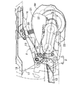
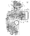
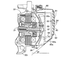
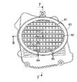
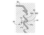
図1〜図9は本発明の一実施例を示すもので、図1はスクータ型の自動二輪車の全体側面図、図2は図1の要部拡大図、図3は図2の3−3線断面図、図4は図3の4−4線矢視図、図5は図4の5−5線断面図、図6はカバーの側面図、図7は図6の7−7線断面図、図8は図6の8−8線断面図、図9は金型装置の一部を示す断面図である。 1 to 9 show an embodiment of the present invention. FIG. 1 is an overall side view of a scooter type motorcycle, FIG. 2 is an enlarged view of the main part of FIG. 1, and FIG. 3 is 3-3 of FIG. 4 is a sectional view taken along line 4-4 in FIG. 3, FIG. 5 is a sectional view taken along line 5-5 in FIG. 4, FIG. 6 is a side view of the cover, and FIG. 7 is a sectional view taken along line 7-7 in FIG. 8 is a sectional view taken along line 8-8 in FIG. 6, and FIG. 9 is a sectional view showing a part of the mold apparatus.
先ず図1および図2において、操向ハンドル11により操舵される前輪Wfとスイング式のパワーユニットPにより駆動される後輪Wrとを備えたスクータ型の自動二輪車Vの車体フレームFは、フロントフレーム12、センターフレーム13およびリヤフレーム14に3分割される。フロントフレーム12は、ヘッドパイプ121 、ダウンチューブ122 およびステップフロア支持部123 を一体に備えたアルミ合金の鋳造品から構成される。パワーユニットPがピボット15を介して上下揺動自在に支持されるセンターフレーム13はアルミ合金の鋳造品から構成され、前記フロントフレーム12の後端に結合される。パワーユニットPの後上方に延びるリヤフレーム14は環状のパイプ材から構成され、その上面に燃料タンク16が支持される。センターフレーム13の上面にはヘルメットケース17が支持されており、シート18を一体に有するカバー19によってヘルメットケース17および燃料タンク16が開閉自在に覆われる。
1 and 2, a vehicle body frame F of a scooter type motorcycle V having a front wheel Wf that is steered by a
パワーユニットPは、シリンダを車体前方に向けて配置した水冷式の単気筒4サイクルエンジンEと、エンジンEの左側面から車体後方に延びるベルト式無段変速機Tとを一体に結合して成り、ベルト式無段変速機Tの後部上面がリヤクッション20を介してセンターフレーム13の後端に結合される。ベルト式無段変速機Tの上面にはエアクリーナ21が支持され、ベルト式無段変速機Tの右側面にはマフラー22が支持され、エンジンEの下面には起立・倒伏可能なメインスタンド23が支持される。
The power unit P is formed by integrally connecting a water-cooled single-cylinder four-cycle engine E with a cylinder disposed toward the front of the vehicle body and a belt-type continuously variable transmission T extending from the left side surface of the engine E to the rear of the vehicle body. The rear upper surface of the belt type continuously variable transmission T is coupled to the rear end of the
図3および図4において、エンジンEは、クランクシャフト31に沿って鉛直方向に延びる割り面30により分割された第1エンジンブロック32および第2エンジンブロック33を備えており、第1エンジンブロック32はシリンダブロック321 およびクランクケース半部322 を構成し、第2エンジンブロック33はクランクケースの他の半部を構成する。第1エンジンブロック32の前端にはシリンダヘッド34が結合され、シリンダヘッド34の前端にはヘッドカバー35が結合される。第1および第2エンジンブロック32,33の右側面には発電機カバー36が結合される。
3 and 4, the engine E includes a
ベルト式無段変速機Tは、相互に結合される右側ケーシング37および左側ケーシング38を備えており、右側ケーシング37の前部右側面が、第1および第2エンジンブロック32,33の左側面に結合される。また右側ケーシング37の後部右側面には減速機ケーシング39が結合される。
The belt type continuously variable transmission T includes a right casing 37 and a
第1エンジンブロック32が備えるシリンダ41の内部に摺動自在に嵌合するピストン42は、コネクティングロッド43を介してクランクシャフト31に連接される。シリンダヘッド34にはカムシャフト44が回転自在に支持されており、シリンダヘッド34に設けられた吸気バルブおよび排気バルブ(図示せず)が前記カムシャフト44によって開閉駆動される。第1エンジンブロック32に設けられたチェーン通路40内にはタイミングチェーン45が収納され、該タイミングチェーン45が、クランクシャフト31に設けられた駆動スプロケット46とカムシャフト44に設けられた従動スプロケット47とに巻き掛けられる。これによりカムシャフト44は、クランクシャフト31の2回転につき1回転する。
A piston 42 slidably fitted into a cylinder 41 included in the
右側ケーシング37および左側ケーシング38の内部に突出するクランクシャフト31の左端には駆動プーリ54が設けられる。該駆動プーリ54は、クランクシャフト31に固定された固定側プーリ半体55と、固定側プーリ半体55に対して接近・離間可能な可動側プーリ半体56とを備えており、可動側プーリ半体56はクランクシャフト31の回転数の増加に応じて半径方向外側に移動する遠心ウエイト57によって、固定側プーリ半体55に接近する方向に付勢される。
A
右側ケーシング37の後部および減速機ケーシング39間に支持された出力軸58に設けられた従動プーリ59は、出力軸58に相対回転可能に支持された固定側プーリ半体60と、固定側プーリ半体60に対して接近・離間可能な可動側プーリ半体61とを備えており、可動側プーリ半体61はスプリング62で固定側プーリ半体60に向けて付勢される。また固定側プーリ半体60と出力軸58との間に発進用クラッチ63が設けられる。そして駆動プーリ54および従動プーリ59間に無端状のVベルト64が巻き掛けられる。
A driven pulley 59 provided on an output shaft 58 supported between the rear portion of the right casing 37 and the
右側ケーシング37および減速機ケーシング39間には前記出力軸58と平行な中間軸65および車軸66が支持されており、出力軸58、中間軸65および車軸66間に減速ギヤ列67が設けられる。そして減速機ケーシング39を貫通して右側に突出する車軸66の右端に後輪Wrが設けられる。
An
而して、クランクシャフト31の回転動力は駆動プーリ54に伝達され、該駆動プーリ54からVベルト64、従動プーリ59、発進用クラッチ63および減速ギヤ列67を介して後輪Wrに伝達される。
Thus, the rotational power of the
エンジンEの低速回転時には、駆動プーリ54の遠心ウエイト57に作用する遠心力が小さいため、従動プーリ59のスプリング62によって固定側プーリ半体60および可動側プーリ半体61間の溝幅が減少し、変速比はLOWになっている。この状態からクランクシャフト31の回転数が増加すると、遠心ウエイト57に作用する遠心力が増加して駆動プーリ54の固定側プーリ半体55および可動側プーリ半体56間の溝幅が減少し、それに伴って従動プーリ59の固定側プーリ半体60および可動側プーリ半体61間の溝幅が増加するため、変速比はLOWからTOPに向かって無段で変化する。
Since the centrifugal force acting on the centrifugal weight 57 of the
クランクシャフト31の右側に設けられた交流発電機68は発電機カバー36により覆われており、その発電機カバー36の右側に被冷却物としてのラジエータ69が設けられる。このラジエータ69に冷却風を供給すべく、クランクシャフト31の右端に固定された冷却ファン70が交流発電機68およびラジエータ69間に配置される。また内部にサーモスタット71を収納したサーモスタットケース72がシリンダヘッド34の右側面に結合されており、カムシャフト44の右端に設けられた冷却水ポンプ73がシリンダヘッド34およびサーモスタットケース72によって囲まれた空間に収納される。
The
図4から明らかなように、ラジエータ69の前下部とサーモスタットケース52とが冷却水配管74で接続され、サーモスタットケース52と第1エンジンブロック32とが冷却水配管75で接続される。また後輪Wrを上方から覆うリヤフェンダー76には、ラジエータ69の後上部に接続される注水管77が着脱可能に締結されており、この注水管77とシリンダヘッド34とが冷却水配管78で接続される。
As is apparent from FIG. 4, the front lower portion of the
エンジンEの暖機運転が完了した状態では、カムシャフト44により駆動される冷却水ポンプ73から排出された冷却水は、サーモスタットケース72および冷却水配管75を経て第1エンジンブロック32およびシリンダヘッド34内のウオータジャケットに供給され、そこを通過する間にエンジンEを冷却した後に冷却水配管78を経てラジエータ69に供給される。そしてラジエータ69を通過する間に温度低下した冷却水は、冷却水配管74およびサーモスタット71を経て前記冷却水ポンプ73に戻される。一方、エンジンEが暖機運転中であって冷却水温度が低いときにはサーモスタット71が作動し、冷却水はラジエータ69を通過することなくエンジンEの内部を循環して速やかに温度上昇する。
In a state where the warm-up operation of the engine E is completed, the cooling water discharged from the cooling
図5〜図8を併せて参照して、クランクシャフト31に固着される冷却ファン70と、該冷却ファン70の外方に配置されるラジエータ69とは、発電機カバー36に締結される合成樹脂製のカバー80で覆われる。而して該カバー80は、このスクータ型自動二輪車の右側で最も突出した位置に配置されることになり、該自動二輪車の右側へのバンク角αが、カバー80で規制されることになるので、カバー80の下部側壁80aは、外側方に向かうにつれて上方位置となるように傾斜して形成され、ラジエータ69の下部69aも、前記下部側壁80aに対応して傾斜するように形成される。
5 to 8 together, the cooling
カバー80には、該カバー80内に導入する冷却空気の整流、カバー80内で発生する騒音の外部への洩れ抑制、ならびにカバー80内への異物の侵入防止を図るようにして、外部からの冷却空気ラジエータ69に導くルーバー81が設けられており、該ルーバー81は、ラジエータ69に向けて開口してカバー80に設けられる冷却空気取入口82を複数の空気流通路83,83…に分割する複数のフィン84,84…が、カバー80に一体に設けられて成るものである。
The
前記冷却空気取入口82は、前記バンク角αを稼ぐために、自動二輪車の前後方向に長い楕円形状に形成されており、該冷却空気取入口82の中心線Cがクランクシャフト31の軸線よりも上方位置に配置されるように、カバー80の上部側に偏った位置に配置される。
The cooling
各フィン84,84…は、自動二輪車の前後方向に長く延びるようにして形成されており、上下方向にほぼ等間隔をあけて冷却空気取入口82に配置される。しかも各フィン84,84…は、それらのフィン84,84…相互間の空気流通路83の外端中心および内端中心間を結ぶ直線Lが前記冷却空気取入口82の中心線Cに対して傾斜するように形成されるものであり、この実施例では、各空気流通路83の外端中心が内端中心よりも下方にあるようにして、前記直線Lが前記中心線Cに対して傾斜する。
Each
しかもフィン84は、冷却空気取入口82の中心線Cに対して傾斜して延びるとともに冷却空気取入口82の外端周縁部に外端を面一に連ならせるフィン主部84aと、該フィン主部84の外端に鈍角をなして面一に連設されて下方側で隣接のフィン84側に張出す張出部84bとから成るものであり、各フィン84が、そのような形状を有するものであることにより、各フィン84,84…の外端相互の間隔が各フィン84,84…の内端相互の間隔よりも狭くなる。
In addition, the
また各フィン84,84…相互間は、上下方向に延びる複数の補強部85,85…で相互に一体に連結されるのであるが、それらの補強部85,85の外端位置は、前記張出部84bの内面位置と同一に設定される。
The
このようなルーバー81からカバー80内に導入される空気は、冷却ファン70で吸引されてラジエータ69を通過し、ラジエータ69内の冷却水を冷却し、カバー80の下部に設けられている空気排出口86から外部に排出される。
The air introduced into the
ところで、冷却ファン70は、図5で明示するように、発電機カバー36の端壁36aに設けられている貫通孔87を貫通するクランクシャフト31の端部に固着されるものであり、貫通孔87の内面およびクランクシャフト31の外面間にはカバー80内に通じる環状の間隙が生じている。このため、冷却ファン70の作動時に冷却ファン70および端壁36a間の間隙88に負圧が生じると、発電機カバー36内にも負圧が生じ、発電機カバー36と、第1、第2エンジンブロック32,33との結合面からダストや水の侵入が生じる可能性がある。そこで、冷却ファン70は、発電機カバー36の端壁36aに比較的長い距離にわたって対向するように形成されており、冷却ファン70および端壁36a間の間隙88に負圧が生じることを極力防止している。
Incidentally, as clearly shown in FIG. 5, the cooling
図9において、カバー80を成形するためのカバー成形用金型装置は、相互に近接・離反可能な第1および第2金型91,92を備えるものであり、第1金型91には、フィン84におけるフィン主部84aの外側面および外端面ならびに張出部84bの外面および先端面を形成する第1成形部91aが設けられ、第2金型92には、フィン主部84aの内側面および内端面ならびに張出部84bの内面を形成する第2成形部92aが設けられる。
In FIG. 9, a cover molding mold apparatus for molding the
次にこの実施例の作用について説明すると、カバー80に設けられるルーバー81を構成する複数のフィン84,84…が、それらのフィン84,84…の外端相互の間隔を各フィン84,84…の内端相互の間隔よりも狭くした形状に形成されている。したがって各フィン84,84…の外端相互の間隔を比較的狭く設定することで、カバー80内への異物の侵入を効果的に防止することができる。また各フィン84,84…の内端相互の間隔は比較的広いので、各フィン84,84…相互間の空気流通路83,83…の流通面積は、各フィン84,84…の外端側の一部で小さくなるものの、空気流通路83,83…の全長にわたって小さくなることはなく、各空気流通路83,83…を流通する冷却空気の流通抵抗が大幅に増大することを避けて、冷却空気を各空気流通路83,83…で整流しつつカバー80内に円滑に導入し、ラジエータ69を効果的に冷却することができる。
Next, the operation of this embodiment will be described. A plurality of
しかもフィン84が、冷却空気取入口82の中心線Cに対して傾斜して延びるとともに冷却空気取入口82の外端周縁部に外端を面一に連ならせるフィン主部84と、該フィン主部84の外端に鈍角をなして面一に連設されて隣接のフィン84側に張出す張出部84bとから成るものであり、フィン84の外端側の肉厚を部分的に厚くするだけで、フィン84,84…の外端相互の間隔を各フィン84,84…の内端相互の間隔よりも狭くしているので、フィン84,84…すなわちカバー80の重量が大きく増大することを回避することができる。
In addition, the
しかも各フィン84は、自動二輪車の下部に配置されるカバー80に、外側方に向かうにつれて下方位置となるように傾斜して形成されているので、自動二輪車の右側方にいる人の視線からカバー80内を確実に隠すことができ、商品性を向上することができる。
Moreover, the
さらにカバー80を成形するためのカバー成形用金型装置は、フィン主部84aの外側面および外端面ならびに張出部84bの外面および先端面を形成する第1成形部91aを有する第1金型91と、フィン主部84aの内側面および内端面ならびに張出部84bの内面を形成する第2成形部92aを有する第2金型92とを備えるものであり、第1および第2金型91,92の型割り面を、フィン84の外端位置よりも内方側に設定するようにして、フィン84の外端部にバリやシャープジエッジが生じることを防止してカバー80の外観性を高め、商品性を向上することができる。
Furthermore, the cover molding mold apparatus for molding the
また第2金型92が有する第2成形部92aの先端で張出部84bの内面を形成するようにして、第2成形部92aの先端幅W2ならびに第1成形部91aの先端幅W1を確保しつつフィン84相互の間隔を狭めることができ、これによってもカバー80の商品性を向上することができる。
In addition, the tip end width W2 of the
以上、本発明の実施例を詳述したが、本発明は上記実施例に限定されるものではなく、特許請求の範囲に記載された本発明を逸脱することなく種々の設計変更を行なうことが可能である。 Although the embodiments of the present invention have been described in detail above, the present invention is not limited to the above-described embodiments, and various design changes can be made without departing from the present invention described in the claims. Is possible.
たとえば上記実施例では、ラジエータ69を覆うカバー80に本発明を適用した場合について説明したが、本発明は、被冷却物を覆うカバーに設けられるルーバーに広く適用可能である。
For example, in the above embodiment, the case where the present invention is applied to the
69・・・被冷却物としてのラジエータ
80・・・カバー
81・・・ルーバー
82・・・冷却空気取入口
83・・・空気流通路
84・・・フィン
84a・・・フィン主部
84b・・・張出部
91・・・第1金型
91a・・・第1成形部
92・・・第2金型
92a・・・第2成形部
C・・・中心線
L・・・直線
69 ...
Claims (3)
Priority Applications (1)
| Application Number | Priority Date | Filing Date | Title |
|---|---|---|---|
| JP2007175591A JP4638469B2 (en) | 2007-07-03 | 2007-07-03 | Scooter type motorcycle |
Applications Claiming Priority (1)
| Application Number | Priority Date | Filing Date | Title |
|---|---|---|---|
| JP2007175591A JP4638469B2 (en) | 2007-07-03 | 2007-07-03 | Scooter type motorcycle |
Related Parent Applications (1)
| Application Number | Title | Priority Date | Filing Date |
|---|---|---|---|
| JP15142299A Division JP4280358B2 (en) | 1999-05-31 | 1999-05-31 | Cover with louver, mold apparatus for molding cover, and engine |
Publications (2)
| Publication Number | Publication Date |
|---|---|
| JP2007315744A true JP2007315744A (en) | 2007-12-06 |
| JP4638469B2 JP4638469B2 (en) | 2011-02-23 |
Family
ID=38849753
Family Applications (1)
| Application Number | Title | Priority Date | Filing Date |
|---|---|---|---|
| JP2007175591A Expired - Lifetime JP4638469B2 (en) | 2007-07-03 | 2007-07-03 | Scooter type motorcycle |
Country Status (1)
| Country | Link |
|---|---|
| JP (1) | JP4638469B2 (en) |
Cited By (2)
| Publication number | Priority date | Publication date | Assignee | Title |
|---|---|---|---|---|
| US7900372B2 (en) * | 2008-04-18 | 2011-03-08 | Mabe Canada Inc. | Clothes dryer with louvre cover |
| WO2018083640A1 (en) * | 2016-11-04 | 2018-05-11 | Piaggio & C. S.P.A | Motorcycle engine cooling system |
Families Citing this family (2)
| Publication number | Priority date | Publication date | Assignee | Title |
|---|---|---|---|---|
| JP5898046B2 (en) * | 2012-10-26 | 2016-04-06 | 本田技研工業株式会社 | Water-cooled internal combustion engine for saddle-ride type vehicles |
| JP5898047B2 (en) * | 2012-10-26 | 2016-04-06 | 本田技研工業株式会社 | Water-cooled internal combustion engine for saddle-ride type vehicles |
Citations (4)
| Publication number | Priority date | Publication date | Assignee | Title |
|---|---|---|---|---|
| JPS5945176U (en) * | 1982-09-17 | 1984-03-26 | 本田技研工業株式会社 | Engine cooling systems for motorcycles, etc. |
| JPS6095125A (en) * | 1983-10-31 | 1985-05-28 | Suzuki Motor Co Ltd | Engine of forcedly air cooling type |
| JPS62107222A (en) * | 1985-11-05 | 1987-05-18 | Honda Motor Co Ltd | Engine cooling device |
| JPH0754653A (en) * | 1993-08-09 | 1995-02-28 | Suzuki Motor Corp | Forced cooling device for scooter type vehicle |
-
2007
- 2007-07-03 JP JP2007175591A patent/JP4638469B2/en not_active Expired - Lifetime
Patent Citations (4)
| Publication number | Priority date | Publication date | Assignee | Title |
|---|---|---|---|---|
| JPS5945176U (en) * | 1982-09-17 | 1984-03-26 | 本田技研工業株式会社 | Engine cooling systems for motorcycles, etc. |
| JPS6095125A (en) * | 1983-10-31 | 1985-05-28 | Suzuki Motor Co Ltd | Engine of forcedly air cooling type |
| JPS62107222A (en) * | 1985-11-05 | 1987-05-18 | Honda Motor Co Ltd | Engine cooling device |
| JPH0754653A (en) * | 1993-08-09 | 1995-02-28 | Suzuki Motor Corp | Forced cooling device for scooter type vehicle |
Cited By (4)
| Publication number | Priority date | Publication date | Assignee | Title |
|---|---|---|---|---|
| US7900372B2 (en) * | 2008-04-18 | 2011-03-08 | Mabe Canada Inc. | Clothes dryer with louvre cover |
| WO2018083640A1 (en) * | 2016-11-04 | 2018-05-11 | Piaggio & C. S.P.A | Motorcycle engine cooling system |
| TWI742190B (en) * | 2016-11-04 | 2021-10-11 | 義大利商比雅久股份有限公司 | Cooling system for an internal combustion engine of a motorcycle and motorcycle having the same |
| US11458832B2 (en) | 2016-11-04 | 2022-10-04 | Piaggio & C. S.P.A. | Motorcycle engine cooling system |
Also Published As
| Publication number | Publication date |
|---|---|
| JP4638469B2 (en) | 2011-02-23 |
Similar Documents
| Publication | Publication Date | Title |
|---|---|---|
| JP4732375B2 (en) | Forced air-cooled internal combustion engine | |
| JP4953950B2 (en) | Cooling device for small vehicle engine | |
| JP6476301B2 (en) | Power unit for saddle-ride type vehicles | |
| JP2007038736A (en) | Saddle riding vehicle | |
| JP4638469B2 (en) | Scooter type motorcycle | |
| JP5703183B2 (en) | Scooter type motorcycle | |
| EP2620611B1 (en) | Internal combustion engine and straddle-type vehicle including the same | |
| JP4280358B2 (en) | Cover with louver, mold apparatus for molding cover, and engine | |
| JP3777298B2 (en) | Radiator mounting structure in vehicles | |
| JP3819700B2 (en) | Radiator device for vehicle | |
| US11180021B2 (en) | Vehicle | |
| JP2009019582A (en) | Radiator device for small vehicles | |
| EP2620612A2 (en) | Internal combustion engine and straddle-type vehicle including the same | |
| JP6104304B2 (en) | Lower cowl structure of saddle riding type vehicle | |
| JP4145425B2 (en) | Radiator filler neck mounting structure for motorcycles | |
| JP2010064706A (en) | Cooling device for motorcycle engine and motorcycle | |
| JP6561486B2 (en) | Cooling fan structure for internal combustion engine | |
| EP2272740A1 (en) | Motorcycle | |
| TWI551775B (en) | Forced air-cooling type internal combustion engine and saddled vehicle having the same | |
| JP6340809B2 (en) | Engine cooling structure | |
| JP2014070621A (en) | Air-cooled internal combustion engine and saddle type vehicle with the same | |
| JP6763273B2 (en) | Motorcycle cooling system | |
| JP7333372B2 (en) | power unit | |
| JP3686077B2 (en) | Radiator device for vehicle | |
| JP2011157977A (en) | Vehicle equipped with internal combustion engine with air exhaust duct |
Legal Events
| Date | Code | Title | Description |
|---|---|---|---|
| A977 | Report on retrieval |
Free format text: JAPANESE INTERMEDIATE CODE: A971007 Effective date: 20100426 |
|
| A131 | Notification of reasons for refusal |
Free format text: JAPANESE INTERMEDIATE CODE: A131 Effective date: 20100512 |
|
| A521 | Written amendment |
Free format text: JAPANESE INTERMEDIATE CODE: A523 Effective date: 20100709 |
|
| A131 | Notification of reasons for refusal |
Free format text: JAPANESE INTERMEDIATE CODE: A131 Effective date: 20100811 |
|
| A521 | Written amendment |
Free format text: JAPANESE INTERMEDIATE CODE: A523 Effective date: 20100916 |
|
| TRDD | Decision of grant or rejection written | ||
| A01 | Written decision to grant a patent or to grant a registration (utility model) |
Free format text: JAPANESE INTERMEDIATE CODE: A01 Effective date: 20101102 |
|
| A01 | Written decision to grant a patent or to grant a registration (utility model) |
Free format text: JAPANESE INTERMEDIATE CODE: A01 |
|
| A61 | First payment of annual fees (during grant procedure) |
Free format text: JAPANESE INTERMEDIATE CODE: A61 Effective date: 20101125 |
|
| FPAY | Renewal fee payment (event date is renewal date of database) |
Free format text: PAYMENT UNTIL: 20131203 Year of fee payment: 3 |
|
| R150 | Certificate of patent or registration of utility model |
Ref document number: 4638469 Country of ref document: JP Free format text: JAPANESE INTERMEDIATE CODE: R150 Free format text: JAPANESE INTERMEDIATE CODE: R150 |
|
| EXPY | Cancellation because of completion of term |