JP2007332995A - Cage for ball bearing and ball bearing using the same - Google Patents
Cage for ball bearing and ball bearing using the same Download PDFInfo
- Publication number
- JP2007332995A JP2007332995A JP2006162411A JP2006162411A JP2007332995A JP 2007332995 A JP2007332995 A JP 2007332995A JP 2006162411 A JP2006162411 A JP 2006162411A JP 2006162411 A JP2006162411 A JP 2006162411A JP 2007332995 A JP2007332995 A JP 2007332995A
- Authority
- JP
- Japan
- Prior art keywords
- cage
- ball bearing
- ball
- pockets
- Prior art date
- Legal status (The legal status is an assumption and is not a legal conclusion. Google has not performed a legal analysis and makes no representation as to the accuracy of the status listed.)
- Pending
Links
Images
Classifications
-
- F—MECHANICAL ENGINEERING; LIGHTING; HEATING; WEAPONS; BLASTING
- F16—ENGINEERING ELEMENTS AND UNITS; GENERAL MEASURES FOR PRODUCING AND MAINTAINING EFFECTIVE FUNCTIONING OF MACHINES OR INSTALLATIONS; THERMAL INSULATION IN GENERAL
- F16C—SHAFTS; FLEXIBLE SHAFTS; ELEMENTS OR CRANKSHAFT MECHANISMS; ROTARY BODIES OTHER THAN GEARING ELEMENTS; BEARINGS
- F16C33/00—Parts of bearings; Special methods for making bearings or parts thereof
- F16C33/30—Parts of ball or roller bearings
- F16C33/38—Ball cages
- F16C33/41—Ball cages comb-shaped
- F16C33/412—Massive or moulded comb cages, e.g. snap ball cages
- F16C33/414—Massive or moulded comb cages, e.g. snap ball cages formed as one-piece cages, i.e. monoblock comb cages
- F16C33/416—Massive or moulded comb cages, e.g. snap ball cages formed as one-piece cages, i.e. monoblock comb cages made from plastic, e.g. injection moulded comb cages
-
- F—MECHANICAL ENGINEERING; LIGHTING; HEATING; WEAPONS; BLASTING
- F16—ENGINEERING ELEMENTS AND UNITS; GENERAL MEASURES FOR PRODUCING AND MAINTAINING EFFECTIVE FUNCTIONING OF MACHINES OR INSTALLATIONS; THERMAL INSULATION IN GENERAL
- F16C—SHAFTS; FLEXIBLE SHAFTS; ELEMENTS OR CRANKSHAFT MECHANISMS; ROTARY BODIES OTHER THAN GEARING ELEMENTS; BEARINGS
- F16C33/00—Parts of bearings; Special methods for making bearings or parts thereof
- F16C33/30—Parts of ball or roller bearings
- F16C33/38—Ball cages
- F16C33/3831—Ball cages with hybrid structure, i.e. with parts made of distinct materials
-
- F—MECHANICAL ENGINEERING; LIGHTING; HEATING; WEAPONS; BLASTING
- F16—ENGINEERING ELEMENTS AND UNITS; GENERAL MEASURES FOR PRODUCING AND MAINTAINING EFFECTIVE FUNCTIONING OF MACHINES OR INSTALLATIONS; THERMAL INSULATION IN GENERAL
- F16C—SHAFTS; FLEXIBLE SHAFTS; ELEMENTS OR CRANKSHAFT MECHANISMS; ROTARY BODIES OTHER THAN GEARING ELEMENTS; BEARINGS
- F16C33/00—Parts of bearings; Special methods for making bearings or parts thereof
- F16C33/30—Parts of ball or roller bearings
- F16C33/38—Ball cages
- F16C33/44—Selection of substances
-
- F—MECHANICAL ENGINEERING; LIGHTING; HEATING; WEAPONS; BLASTING
- F16—ENGINEERING ELEMENTS AND UNITS; GENERAL MEASURES FOR PRODUCING AND MAINTAINING EFFECTIVE FUNCTIONING OF MACHINES OR INSTALLATIONS; THERMAL INSULATION IN GENERAL
- F16C—SHAFTS; FLEXIBLE SHAFTS; ELEMENTS OR CRANKSHAFT MECHANISMS; ROTARY BODIES OTHER THAN GEARING ELEMENTS; BEARINGS
- F16C33/00—Parts of bearings; Special methods for making bearings or parts thereof
- F16C33/30—Parts of ball or roller bearings
- F16C33/66—Special parts or details in view of lubrication
- F16C33/6637—Special parts or details in view of lubrication with liquid lubricant
- F16C33/6681—Details of distribution or circulation inside the bearing, e.g. grooves on the cage or passages in the rolling elements
-
- F—MECHANICAL ENGINEERING; LIGHTING; HEATING; WEAPONS; BLASTING
- F16—ENGINEERING ELEMENTS AND UNITS; GENERAL MEASURES FOR PRODUCING AND MAINTAINING EFFECTIVE FUNCTIONING OF MACHINES OR INSTALLATIONS; THERMAL INSULATION IN GENERAL
- F16C—SHAFTS; FLEXIBLE SHAFTS; ELEMENTS OR CRANKSHAFT MECHANISMS; ROTARY BODIES OTHER THAN GEARING ELEMENTS; BEARINGS
- F16C41/00—Other accessories, e.g. devices integrated in the bearing not relating to the bearing function as such
- F16C41/008—Identification means, e.g. markings, RFID-tags; Data transfer means
-
- F—MECHANICAL ENGINEERING; LIGHTING; HEATING; WEAPONS; BLASTING
- F16—ENGINEERING ELEMENTS AND UNITS; GENERAL MEASURES FOR PRODUCING AND MAINTAINING EFFECTIVE FUNCTIONING OF MACHINES OR INSTALLATIONS; THERMAL INSULATION IN GENERAL
- F16C—SHAFTS; FLEXIBLE SHAFTS; ELEMENTS OR CRANKSHAFT MECHANISMS; ROTARY BODIES OTHER THAN GEARING ELEMENTS; BEARINGS
- F16C19/00—Bearings with rolling contact, for exclusively rotary movement
- F16C19/02—Bearings with rolling contact, for exclusively rotary movement with bearing balls essentially of the same size in one or more circular rows
- F16C19/04—Bearings with rolling contact, for exclusively rotary movement with bearing balls essentially of the same size in one or more circular rows for radial load mainly
- F16C19/06—Bearings with rolling contact, for exclusively rotary movement with bearing balls essentially of the same size in one or more circular rows for radial load mainly with a single row or balls
Landscapes
- Engineering & Computer Science (AREA)
- General Engineering & Computer Science (AREA)
- Mechanical Engineering (AREA)
- Mounting Of Bearings Or Others (AREA)
- Rolling Contact Bearings (AREA)
Abstract
【課題】回転時における潤滑油などの攪拌抵抗をより小さくすることができる新規な玉軸受用保持器およびこれを用いた玉軸受の提供。
【解決手段】内輪1と外輪2間で転動する複数のボール3を保持するための玉軸受用保持器4であって、リング状の保持器本体4aにポケット4bを複数備えると共に、当該保持器本体4aの各ポケット4b、4b間の端面形状を、隣接するポケット4b、4b間で連続するように滑らかな曲面とし、保持器ポケット4bの回転方向上流側縁部3aをボール3組み込み持に弾性変形可能とする。これによって、その周囲の潤滑油がその各ポケット4b、4b間の曲面状の端面に沿ってスムーズに流れるようになるため、その端面部分での流体の攪拌が発生しなくなって攪拌抵抗が大幅に減少すると共に、ボール3の保持器ポケット4bへの組み込み性を向上させる。
【選択図】 図3
A novel ball bearing cage capable of further reducing agitation resistance of lubricating oil or the like during rotation and a ball bearing using the same.
A ball bearing retainer 4 for retaining a plurality of balls 3 that roll between an inner ring 1 and an outer ring 2, the ring-shaped retainer body 4a having a plurality of pockets 4b, and the holding The end face shape between each pocket 4b, 4b of the cage body 4a is a smooth curved surface so as to be continuous between adjacent pockets 4b, 4b, and the upstream edge 3a in the rotational direction of the cage pocket 4b is incorporated into the ball 3 It can be elastically deformed. As a result, the surrounding lubricating oil flows smoothly along the curved end surface between the pockets 4b, 4b, so that the agitation of the fluid does not occur at the end surface portion and the agitation resistance is greatly increased. As well as decreasing, the incorporation of the ball 3 into the cage pocket 4b is improved.
[Selection] Figure 3
Description
本発明は、油浴潤滑下などの深溝玉軸受などのようにボールおよびその保持器の周囲が潤滑油で満たされた玉軸受に係り、特にそのボールを保持するための保持器およびこれを用いた玉軸受に関するものである。 The present invention relates to a ball bearing in which the periphery of the ball and its cage is filled with lubricating oil, such as a deep groove ball bearing under oil bath lubrication, and the like, and in particular, a cage for holding the ball and the use thereof It relates to a ball bearing.
一般に油浴潤滑下などで使用される玉軸受は、図5に示すように、回転する軸体側に支持される内輪1と、静止体側に支持される外輪2と、その間に設けられる複数のボール(転動体)3と、これらボール3を保持するための保持器4から主に構成されている。
そして、この保持器4としては、打抜き保持器やかご形保持器などのように金属材料からなるものが多いが、最近では、金属材料に比べて自己潤滑性や耐摩耗性に優れた合成樹脂材料からなるものが多く採用されてきている。
As shown in FIG. 5, a ball bearing generally used under oil bath lubrication includes an
The
このような合成樹脂製の保持器4としては、例えば図6に示すようないわゆる冠型樹脂保持器4がある。この冠型樹脂保持器4は、リング状をした保持器本体4aの端面に複数のポケット4bがその周方向に沿って一定の間隔を隔てて設けられており、これら各ポケット4b、4b…にそれぞれボール3を回転自在に収容することで、これら各ボール3、3…をそれぞれ一定の間隔を隔てて保持するようになっている。
An example of such a
ところで、図6に示したような冠型樹脂保持器4は、各ポケット4b、4b…に収容されたボール3の脱落を防止するために、各ポケット4b、4b…の縁部には、収容されたボール3を抱えるように突出した爪4c、4cが設けられている。
このため、各ポケット4b、4b…間には大きな溝部4dが形成されることになり、この溝部4dによって冠型樹脂保持器4が回転したときにその周囲の潤滑油を不要に攪拌してしまい、攪拌抵抗による潤滑油の温度上昇や気泡の発生を誘発することがある。
Incidentally, the crown-
For this reason, a
そのため、例えば特許文献1では、保持器4のポケット4b,4b間の空間を空間埋め部材などで埋めることでその空間による潤滑油の攪拌を極力抑え、攪拌抵抗による温度上昇や気泡の発生を防止するようにしている。
また、特許文献2では、保持器4の内周面と外周面の全面に亘って複数の細い溝を形成することで保持器4周囲の潤滑剤などの流体の流れを整流化し、これによって回転トルクの低減および発熱の抑制を図るようにしている。
Moreover, in
ところで、この特許文献1のように保持器4のポケット4b,4b間の空間を空間埋め部材などで埋めることによってその空間などによる潤滑油の攪拌を抑え、攪拌抵抗による温度上昇や気泡の発生をある程度まで抑制することは可能であるが、ボール3をポケット4bへ組み込む場合の変形量が十分でない。
また、特許文献2の技術では、保持器4の内周面と外周面の流体の流れを整流することは可能であるが、保持器4の端面部分の流体の流れまでも整流することは困難である。
そこで、本発明はこのような課題を解決するための案出されたものであり、その主な目的は、回転時における潤滑油などの攪拌抵抗をより小さくすることができると共に、ポケットへのボール組み込み性を改良した新規な玉軸受用保持器およびこれを用いた玉軸受を提供するものである。
By the way, as in
Further, in the technique of
Therefore, the present invention has been devised to solve such problems, and its main purpose is to reduce the agitation resistance of lubricating oil and the like during rotation, and to ball into the pocket. It is intended to provide a novel ball bearing retainer with improved assemblability and a ball bearing using the same.
前記課題を解決するために請求項1の発明は、
内輪と外輪間で転動する複数のボールを保持するための玉軸受用保持器であって、リング状の保持器本体に前記各ボールをその端面側から収容するためのポケットを複数備えると共に、当該保持器本体の各ポケット間の端面形状を、隣接するポケット間で連続するように滑らかな曲面とし、前記ポケットの回転方向上流側の縁部をボール組み込み時に弾性変形可能としたことを特徴とする玉軸受用保持器である。
また、請求項2の発明は、
請求項1に記載の玉軸受用保持器において、前記保持器本体を合成樹脂材料で形成したことを特徴とする玉軸受用保持器である。
In order to solve the above-mentioned problem, the invention of
A ball bearing retainer for retaining a plurality of balls that roll between an inner ring and an outer ring, the ring-shaped retainer body including a plurality of pockets for accommodating each of the balls from its end face side, The end face shape between each pocket of the cage body is a smooth curved surface so as to be continuous between adjacent pockets, and the edge on the upstream side in the rotation direction of the pocket is elastically deformable when the ball is incorporated. It is a cage for ball bearings.
The invention of
2. The ball bearing cage according to
また、請求項3の発明は、
請求項1に記載の玉軸受用保持器において、前記保持器本体の各ポケット間に溝部を形成し、当該溝部に前記各ポケット間の曲面形状を維持すべく弾性変形部材を嵌合したことを特徴とする玉軸受用保持器である。
また、請求項4の発明は、
請求項1〜3のいずれか1項に記載の玉軸受用保持器を回転自在に組み込んだことを特徴とする玉軸受である。
また、請求項5の発明は、
請求項4に記載の玉軸受において、前記外輪または内輪の端面に、前記保持器の回転方向を識別する識別情報を付したことを特徴とする玉軸受である。
The invention of
The ball bearing retainer according to
The invention of
A ball bearing in which the ball bearing retainer according to any one of
The invention of claim 5
The ball bearing according to
請求項1の発明によれば、保持器本体が回転した際にその周囲の潤滑油がその各ポケット間の曲面状の端面に沿ってスムーズに流れるようになるため、その端面部分での流体の攪拌しなくなって攪拌抵抗が大幅に減少する。この結果、攪拌抵抗による潤滑油の温度上昇や気泡の発生などを効果的に抑制することができる。
請求項2の発明によれば、前記保持器本体を合成樹脂材料で形成したため、前記保持器本体を容易に変形することができる。これによって、各ポケットへのボールの組み込みや交換作業を容易に行うことができる。
According to the first aspect of the present invention, when the cage body rotates, the surrounding lubricating oil flows smoothly along the curved end surfaces between the pockets. Stirring resistance is greatly reduced because stirring is stopped. As a result, it is possible to effectively suppress an increase in the temperature of the lubricating oil due to the stirring resistance and the generation of bubbles.
According to the invention of
請求項3の発明によれば、請求項2の発明と同様に前記保持器本体を容易に変形することが可能となるため、各ポケットへのボールの組み込みや交換作業を容易に行うことができる。
請求項4の発明によれば、玉軸受に前記請求項1〜3のいずれかに記載の玉軸受用保持器を回転自在に組み込んだことから、攪拌抵抗による潤滑油の温度上昇や気泡の発生などが効果的に抑制されるため、従来よりもさらに長期に亘って安定した軸受性能を維持することができる。
請求項5の発明によれば、前記外輪または内輪の端面に、前記保持器の回転方向を識別する識別情報を付したことから、その識別情報に基づいて前記保持器を玉軸受に組み込み、かつその玉軸受をハウジングなどに組み込むことにより、その回転方向を間違えずに正確に組み込むことができる。
According to the invention of
According to the invention of
According to the invention of claim 5, since the identification information for identifying the rotation direction of the cage is attached to the end face of the outer ring or the inner ring, the cage is incorporated in the ball bearing based on the identification information, and By incorporating the ball bearing in a housing or the like, it is possible to accurately incorporate the rotation direction without making a mistake.
以下、本発明の実施形態について図面を参照しながら説明する。
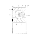
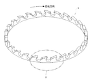
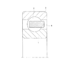
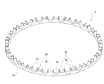
図1は、本発明に係る玉軸受10の実施の一形態を示したものであり、図2はこの玉軸受10に組み込まれる保持器4を示す斜視図である。
図示するようにこの玉軸受10は、外周面に断面円弧状の軌道溝1aを有する内輪1と、内周面に前記内輪1の軌道面1aに対向すべく同じく断面円弧状の軌道溝2aを有する外輪2と、これら軌道溝1a,2a間に転動自在に配置される複数のボール(転動体)3,3…と、これら各ボール3,3…を一定の間隔を隔てて保持するリング状の保持器4とを備えた構造となっている。
Hereinafter, embodiments of the present invention will be described with reference to the drawings.
FIG. 1 shows an embodiment of a ball bearing 10 according to the present invention, and FIG. 2 is a perspective view showing a
As shown in the figure, this ball bearing 10 has an
そして、本実施の形態にあっては、これら各ボール3,3…をその周方向に沿って一定の間隔を隔てて保持するリング状の保持器4の一端面が図2および図3に示すように滑らかな連続した波形形状となっている。
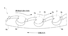
すなわち、同図に示すようにこの保持器本体4aの一端面側からその周方向に沿って一定の間隔を隔てて複数のポケット4b,4b…が形成されていると共に、それら各ポケット4b,4b…にボール3の一部が露出した状態で転動自在に収容されている。そして、この各ポケット4b,4b…間の形状がその露出したボール3の表面(曲面)部分と連続するように曲面状に形成されており、この各ポケット4b,4b…に収容されたボール3の露出面と、その各ポケット4b,4b…間の表面形状とによって曲面が連続した波形端面が形成されるようになっている。
And in this Embodiment, the end surface of the ring-shaped holder |
That is, as shown in the figure, a plurality of
つまり、図6などに示したように従来の保持器4の場合は、各ポケット4b,4b…にボール3を収容したときに、そのポケット4bの爪部4cと収容されたボール3との境界部に急激な段差が多数形成されてしまうのに対し、本発明の保持器4の場合は図3に示すように特に各ポケット4b,4b…の回転方向上流側の縁部3aが滑らかに盛り上がってボール3の露出面頂部と連続するような形状となっている。そして、この各ポケット4b,4b…の回転方向下流側の縁部3bも、ボール3の露出面底部と連続するような凸状の曲面形状となってそのまま滑らかに盛り上がって次のボール3の露出面頂部と再び連続するような形状となっており、ボール3の露出面の前後において急激な段差部分が皆無となっている。
That is, in the case of the
従って、図3に示すように各ボール3,3…の転動に伴って潤滑油の流れが矢印の方向に向かうようにこの保持器4を図2の矢印の回転方向に回転すると、各ポケット4b,4b…が形成された保持器本体4a側の端面においてその周囲の潤滑油がその波形端面に沿ってスムーズに流れることになる。
これによって、その端面部分で潤滑油が無用に攪拌しなくなって攪拌抵抗が大幅に減少するため、攪拌抵抗による潤滑油の温度上昇や気泡の発生などを効果的に抑制することができる。
Therefore, when the
As a result, the lubricating oil is not unnecessarily stirred at the end face portion, and the stirring resistance is greatly reduced. Therefore, the temperature rise of the lubricating oil due to the stirring resistance and the generation of bubbles can be effectively suppressed.
さらに、回転方向上流側の縁部3aおよび下流側の縁部3bは、それぞれその先端が細くなっており、ボール3をポケット4bに着脱するにあたってこの部分が変形し易いので、ポケット4bへのボール3の着脱時の作業性が向上する。
また、この保持器4を弾性変形し易い材料、例えばフェノール樹脂や、四フッ化エチレン樹脂(PTFE、テフロン(登録商標))、ポリアミド(ナイロン)などのように自己潤滑性のみならず可撓性に優れた合成樹脂材料で形成すれば、適度な弾性変形性を発揮することが可能となるため、各ポケット4b,4b…へのボール3の着脱作業をさらに極めて容易に行うことができる。
Furthermore, the
The
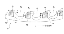
また、この保持器4を、合成樹脂材料のような適度な弾性変形性を有しない剛性が大きい材料、例えば金属などで形成した場合には、図4に示すように、その保持器本体4aの各ポケット間に溝部4dを形成し、その溝部4dに各ポケット間4b,4b…の曲面形状を維持すべく弾性変形部材4e、例えばゴムなどの保持器本体4aより弾性係数が小さい弾性変形部材4eを詰め物として嵌合するようにしても良い。なお、この弾性変形部材としてポリウレタンや発泡スチロールなどの吸音特性が優れる材料を用いることにより、音響特性の向上が図れる。
Further, when the
このような構成にすれば、適度な弾性変形性が発揮されるため、各ポケット4b、4b…へのボール3の着脱作業が容易になると共に、各ポケット間4b,4b…の曲面形状を損なうこともないため、その端面部分での攪拌抵抗を増大させることもなくなる。
また、本実施の形態の保持器4のように、各ポケット4b,4b…の回転方向上流側の縁部3aが回転方向下流側の縁部3bよりも盛り上がるように形成した場合は、その保持器4の回転方向が重要となってくる。すなわち、その回転方向を誤って取り付けると、各ポケット4b,4b…に収容されたボール3の露出面と潤滑油がほぼ直角に衝突してしまい、全く効果が得られないばかりか却って逆効果になってしまう。
With such a configuration, moderate elastic deformability is exhibited, so that it is easy to attach and detach the
Further, when the
そのため、例えば図1に示すように外輪2や内輪3の端面に、保持器4の回転方向を識別する識別情報6を刻印しておけば、その回転方向に対応した保持器4を間違いなく玉軸受に組み付けることができ、かつ、その玉軸受をハウジングなどに組み込むことができる。具体的には、前記回転方向の識別情報としてその回転方向を示す矢印やその軸受や対応する保持器4の型番などの数字記号を用いることができる。
Therefore, for example, as shown in FIG. 1, if
10…玉軸受
1…内輪
2…外輪
3…ボール(転動体)
4…保持器
4a…保持器本体
4b…ポケット
4d…溝
4e…弾性変形部材
6…回転方向識別情報
10 ...
2 ... Outer ring
3. Ball (rolling element)
DESCRIPTION OF
Claims (5)
前記保持器本体を合成樹脂材料で形成したことを特徴とする玉軸受用保持器。 The ball bearing retainer according to claim 1,
A cage for ball bearings, wherein the cage body is formed of a synthetic resin material.
前記保持器本体の各ポケット間に溝部を形成し、当該溝部に前記各ポケット間の曲面形状を維持すべく弾性変形部材を嵌合したことを特徴とする玉軸受用保持器。 The ball bearing retainer according to claim 1,
A ball bearing cage, wherein a groove is formed between each pocket of the cage body, and an elastically deformable member is fitted in the groove to maintain the curved shape between the pockets.
Priority Applications (1)
| Application Number | Priority Date | Filing Date | Title |
|---|---|---|---|
| JP2006162411A JP2007332995A (en) | 2006-06-12 | 2006-06-12 | Cage for ball bearing and ball bearing using the same |
Applications Claiming Priority (1)
| Application Number | Priority Date | Filing Date | Title |
|---|---|---|---|
| JP2006162411A JP2007332995A (en) | 2006-06-12 | 2006-06-12 | Cage for ball bearing and ball bearing using the same |
Publications (1)
| Publication Number | Publication Date |
|---|---|
| JP2007332995A true JP2007332995A (en) | 2007-12-27 |
Family
ID=38932666
Family Applications (1)
| Application Number | Title | Priority Date | Filing Date |
|---|---|---|---|
| JP2006162411A Pending JP2007332995A (en) | 2006-06-12 | 2006-06-12 | Cage for ball bearing and ball bearing using the same |
Country Status (1)
| Country | Link |
|---|---|
| JP (1) | JP2007332995A (en) |
Cited By (2)
| Publication number | Priority date | Publication date | Assignee | Title |
|---|---|---|---|---|
| WO2012043575A1 (en) * | 2010-09-28 | 2012-04-05 | Ntn株式会社 | Fluid dynamic bearing device and assembly method thereof |
| US8534920B2 (en) | 2008-04-22 | 2013-09-17 | Jtekt Corporation | Rolling bearing |
-
2006
- 2006-06-12 JP JP2006162411A patent/JP2007332995A/en active Pending
Cited By (2)
| Publication number | Priority date | Publication date | Assignee | Title |
|---|---|---|---|---|
| US8534920B2 (en) | 2008-04-22 | 2013-09-17 | Jtekt Corporation | Rolling bearing |
| WO2012043575A1 (en) * | 2010-09-28 | 2012-04-05 | Ntn株式会社 | Fluid dynamic bearing device and assembly method thereof |
Similar Documents
| Publication | Publication Date | Title |
|---|---|---|
| JP2009058039A (en) | Roller bearing cage | |
| JP6261719B2 (en) | Spherical roller bearing cage and bearing with cylindrical guide contact surface and radially outwardly directed inner flange | |
| JP2004162879A (en) | Resin cage for rolling bearing | |
| JP2018035944A (en) | Method for manufacturing ball bearing | |
| JP3122529U (en) | Holding device for bearing, bearing and harmonic reducer | |
| EP2811188A2 (en) | Ball bearing | |
| JP2009281399A (en) | Deep groove ball bearing cage and deep groove ball bearing | |
| JPH10238543A (en) | Cage for radial ball bearing | |
| CN203477079U (en) | Crown cage and ball bearing | |
| JP2007332995A (en) | Cage for ball bearing and ball bearing using the same | |
| JP2003028163A (en) | Cage for ball bearing | |
| JP2013068249A (en) | Ball bearing and retainer for ball bearing | |
| JP5272737B2 (en) | Crown type cage and ball bearing | |
| JP5029733B2 (en) | Ball bearing | |
| JP4969548B2 (en) | Ball bearing | |
| JP2012047269A (en) | Ball bearing | |
| JP2011085261A (en) | Roller bearing for electric seat reclining | |
| JP2009275799A (en) | Deep groove ball bearing | |
| JP2002098150A (en) | Ball bearing | |
| WO2010137434A1 (en) | Ball bearing retainer and ball bearing | |
| JP2007078078A (en) | Retainer for rolling ball bearing and its manufacturing method | |
| JP2005155759A (en) | Rolling bearing | |
| JP5050910B2 (en) | Ball bearing cage and ball bearing | |
| JPH0979265A (en) | Crown type cage for ball bearings | |
| JP2006207684A (en) | Rolling bearing |