JP2007502425A - Support device - Google Patents
Support device Download PDFInfo
- Publication number
- JP2007502425A JP2007502425A JP2006523692A JP2006523692A JP2007502425A JP 2007502425 A JP2007502425 A JP 2007502425A JP 2006523692 A JP2006523692 A JP 2006523692A JP 2006523692 A JP2006523692 A JP 2006523692A JP 2007502425 A JP2007502425 A JP 2007502425A
- Authority
- JP
- Japan
- Prior art keywords
- support
- core barrel
- support device
- pressure vessel
- reactor pressure
- Prior art date
- Legal status (The legal status is an assumption and is not a legal conclusion. Google has not performed a legal analysis and makes no representation as to the accuracy of the status listed.)
- Granted
Links
- 230000000295 complement effect Effects 0.000 claims description 22
- 238000006073 displacement reaction Methods 0.000 claims description 10
- 238000000034 method Methods 0.000 claims description 6
- 238000005096 rolling process Methods 0.000 claims description 6
- 238000003466 welding Methods 0.000 claims description 6
- 239000007789 gas Substances 0.000 claims description 5
- 239000001307 helium Substances 0.000 claims description 2
- 229910052734 helium Inorganic materials 0.000 claims description 2
- SWQJXJOGLNCZEY-UHFFFAOYSA-N helium atom Chemical compound [He] SWQJXJOGLNCZEY-UHFFFAOYSA-N 0.000 claims description 2
- 238000009826 distribution Methods 0.000 description 3
- 239000000463 material Substances 0.000 description 3
- 238000001816 cooling Methods 0.000 description 2
- 238000004519 manufacturing process Methods 0.000 description 2
- 230000036316 preload Effects 0.000 description 2
- 230000002159 abnormal effect Effects 0.000 description 1
- 238000005452 bending Methods 0.000 description 1
- 238000009434 installation Methods 0.000 description 1
- 238000005121 nitriding Methods 0.000 description 1
- 239000003758 nuclear fuel Substances 0.000 description 1
- 238000000926 separation method Methods 0.000 description 1
- 230000006641 stabilisation Effects 0.000 description 1
- 238000011105 stabilization Methods 0.000 description 1
Images


Classifications
-
- G—PHYSICS
- G21—NUCLEAR PHYSICS; NUCLEAR ENGINEERING
- G21C—NUCLEAR REACTORS
- G21C13/00—Pressure vessels; Containment vessels; Containment in general
- G21C13/02—Details
- G21C13/024—Supporting constructions for pressure vessels or containment vessels
-
- G—PHYSICS
- G21—NUCLEAR PHYSICS; NUCLEAR ENGINEERING
- G21C—NUCLEAR REACTORS
- G21C13/00—Pressure vessels; Containment vessels; Containment in general
-
- G—PHYSICS
- G21—NUCLEAR PHYSICS; NUCLEAR ENGINEERING
- G21C—NUCLEAR REACTORS
- G21C5/00—Moderator or core structure; Selection of materials for use as moderator
- G21C5/02—Details
- G21C5/10—Means for supporting the complete structure
-
- Y—GENERAL TAGGING OF NEW TECHNOLOGICAL DEVELOPMENTS; GENERAL TAGGING OF CROSS-SECTIONAL TECHNOLOGIES SPANNING OVER SEVERAL SECTIONS OF THE IPC; TECHNICAL SUBJECTS COVERED BY FORMER USPC CROSS-REFERENCE ART COLLECTIONS [XRACs] AND DIGESTS
- Y02—TECHNOLOGIES OR APPLICATIONS FOR MITIGATION OR ADAPTATION AGAINST CLIMATE CHANGE
- Y02E—REDUCTION OF GREENHOUSE GAS [GHG] EMISSIONS, RELATED TO ENERGY GENERATION, TRANSMISSION OR DISTRIBUTION
- Y02E30/00—Energy generation of nuclear origin
- Y02E30/30—Nuclear fission reactors
Landscapes
- Physics & Mathematics (AREA)
- Engineering & Computer Science (AREA)
- Plasma & Fusion (AREA)
- General Engineering & Computer Science (AREA)
- High Energy & Nuclear Physics (AREA)
- Structure Of Emergency Protection For Nuclear Reactors (AREA)
- Devices And Processes Conducted In The Presence Of Fluids And Solid Particles (AREA)
- Prostheses (AREA)
- Materials For Medical Uses (AREA)
- Auxiliary Devices For And Details Of Packaging Control (AREA)
- Non-Reversible Transmitting Devices (AREA)
- Input Circuits Of Receivers And Coupling Of Receivers And Audio Equipment (AREA)
Abstract
原子炉は、原子炉圧力容器12と、該原子炉圧力容器12内に収容される炉心バレル14を含む。原子炉10は更に、単一の垂直支持体16を含み、炉心バレルから原子炉圧力容器に垂直荷重を伝達する。更に横方向支持手段は、サポート16を上回る高さに設けられ、炉心バレル14に対する横方向支持を与える。この装置により、結果として温度変動から生じる応力が低減されることになる。The nuclear reactor includes a reactor pressure vessel 12 and a core barrel 14 accommodated in the reactor pressure vessel 12. The reactor 10 further includes a single vertical support 16 to transmit vertical loads from the core barrel to the reactor pressure vessel. Further, lateral support means are provided at a height above the support 16 to provide lateral support for the core barrel 14. This device results in a reduction of stress resulting from temperature fluctuations.
Description
本発明は、支持装置に関する。本発明はまた、容器を支持する方法に関する。 The present invention relates to a support device. The invention also relates to a method for supporting a container.
温度変動を受ける容器に関して問題がある。温度変化の結果、容器の形状及び/又は寸法が変化する可能性があり、これにより、容器及び/又は容器支持体に望ましくない応力がもたらされるおそれがある。これは、特に温度変化が一様ではない場合に当てはまる。 There are problems with containers subject to temperature fluctuations. As a result of temperature changes, the shape and / or dimensions of the container can change, which can result in undesirable stresses on the container and / or container support. This is especially true when the temperature change is not uniform.
本発明の目的は、この状況を少なくとも緩和すると発明者が考える手段を提供することである。 The object of the present invention is to provide means for the inventors to at least alleviate this situation.
本発明の1つの態様によれば、支持されることになる容器と、容器の重量を支持する単一の垂直支持体と、少なくとも単一の垂直支持体を上回る高さにあり、容器に対する横方向支持を与える横方向支持手段とを備える支持装置を提供する。 According to one aspect of the invention, the container to be supported, a single vertical support for supporting the weight of the container, and at least above the single vertical support, A support device is provided comprising lateral support means for providing directional support.
本発明は、特に、必ずしもこれ以外を排除するものではないが、高温ガス冷却原子炉に用途が見出されると本発明者は考える。 Although the present invention does not necessarily exclude other than this, the present inventor believes that the present invention finds use in a high-temperature gas-cooled nuclear reactor.
従って、容器は、たとえば、原子炉圧力容器を含む高温ガス冷却原子炉の炉心バレルであり、該原子炉圧力容器内に炉心バレルが収容され、垂直支持体は、それぞれが炉心バレルと原子炉圧力容器とに連結される上部及び下部支持部材を備え、これらの間で垂直方向の荷重が伝達される。 Thus, the vessel is, for example, the core barrel of a high temperature gas cooled reactor that includes a reactor pressure vessel, in which the core barrel is housed and the vertical supports are respectively the core barrel and the reactor pressure. An upper and lower support member connected to the container is provided, and a vertical load is transmitted between them.
炉心バレルは、略円筒形の形状とすることができ、略垂直方向に延びる軸線を有し、上部及び下部支持部材は、中央に位置付けられた対向配置の接触面を定める。 The core barrel can be generally cylindrical in shape and have an axis extending in a generally vertical direction, with the upper and lower support members defining opposed contact surfaces positioned centrally.
接触面の少なくとも1つが湾曲することができ、その結果、接触面間の相対移動が転動によって行われてヘリウム環境での運転時に磨耗と表面溶着の可能性が低減される。 At least one of the contact surfaces can be curved, so that the relative movement between the contact surfaces is effected by rolling, reducing the possibility of wear and surface welding when operating in a helium environment.
上部支持部材は下方に面する凹状接触面を定めることができる。下部支持部材は、上方に面する凸状接触面を定めることができる。接触面は部分球形とすることができる。本発明の好適な実施形態においては、凸状接触面の半径は凹状接触面の半径よりも小さい。 The upper support member can define a concave contact surface facing downward. The lower support member can define a convex contact surface facing upward. The contact surface can be partially spherical. In a preferred embodiment of the present invention, the radius of the convex contact surface is smaller than the radius of the concave contact surface.
垂直支持体は、上部支持部材と下部支持部材との間に挿入される中間部材を含むことができる。中間部材は、それぞれが上部及び下部支持部材の相補的接触面と協働する上部及び下部接触面を定めることができる。 The vertical support may include an intermediate member that is inserted between the upper support member and the lower support member. The intermediate member can define upper and lower contact surfaces that each cooperate with complementary contact surfaces of the upper and lower support members.
中間部材の接触面は凸状とすることができ、上部及び下部支持部材の相補的接触面は凹状である。本発明の好適な実施形態においては、各凸状接触面の半径は、相補的凹状接触面の半径よりも小さい。 The contact surface of the intermediate member can be convex, and the complementary contact surfaces of the upper and lower support members are concave. In a preferred embodiment of the invention, the radius of each convex contact surface is less than the radius of the complementary concave contact surface.
横方向支持手段は、炉心バレルを作動上の上端部で又はこれに向けて横方向に支持するように位置付けられる、複数の円周方向に間隔を置いて配置された上部横方向支持体を含むことができる。 The lateral support means includes a plurality of circumferentially spaced upper lateral supports positioned to laterally support the core barrel at or toward the operational upper end. be able to.
各上部横方向支持体は、炉心バレルと原子炉圧力容器とにそれぞれ連結された内側及び外側上部支持部材のセットを含むことができ、各セットの内側及び外側上部支持部材の少なくとも1つは、弾性変形可能な支持体上に取り付けられる。 Each upper lateral support can include a set of inner and outer upper support members coupled to the core barrel and the reactor pressure vessel, respectively, wherein at least one of the inner and outer upper support members of each set includes Mounted on an elastically deformable support.
各上部横方向支持体の内側上部支持部材と外側上部支持部材との間にローラ要素を挟装して、内側及び外側上部支持部材間、並びにこれらが連結される炉心バレルと原子炉圧力容器との間の相対変位を助長することができる。ローラと内側上部支持部材及び外側上部支持部材のうちの少なくとも1つとが相補的ギアを備え、ローラと内側及び外側上部支持部材の相補的軸受面との間の相対変位が確実に転動であって摺動によるものではないようにすることができる。 A roller element sandwiched between an inner upper support member and an outer upper support member of each upper lateral support, between the inner and outer upper support members, and a core barrel and a reactor pressure vessel to which they are connected; The relative displacement between can be encouraged. The roller and at least one of the inner upper support member and the outer upper support member are provided with complementary gears to ensure that the relative displacement between the roller and the complementary bearing surfaces of the inner and outer upper support members is rolling. Therefore, it can be prevented from being caused by sliding.
ローラの使用に加えて、前記軸受面は、溶着を阻止するように処理することができる。この処理は軸受面の窒化を含むことができる。 In addition to the use of rollers, the bearing surface can be treated to prevent welding. This treatment may include nitriding the bearing surface.
内側及び外側上部支持部材の軸受面は傾斜面とすることができる。特に、内側及び外側上部横方向支持部材の軸受面は略平行であり且つ外方上方に傾斜することができる。 The bearing surfaces of the inner and outer upper support members can be inclined surfaces. In particular, the bearing surfaces of the inner and outer upper lateral support members are substantially parallel and can be inclined outwardly upward.
各外側上部支持部材は弾性変形可能な支持体上に取り付けることができ、該弾性変形可能な支持体は、前記原子炉圧力容器に固定される上部支持リング上に取り付けられる。弾性変形可能な支持体は、離間した位置に上部支持リングに連結された支持ポストのペアと、支持ポスト間に延び且つ外側上部支持部材が取り付けられる弾性変形可能なガイドビームとを含むことができる。ガイドビームの位置を調整可能とすることができることによって、内側及び外側上部支持部材の相対位置が調整可能となる。 Each outer upper support member can be mounted on an elastically deformable support, and the elastically deformable support is mounted on an upper support ring fixed to the reactor pressure vessel. The elastically deformable support may include a pair of support posts coupled to the upper support ring at spaced locations and an elastically deformable guide beam extending between the support posts and having an outer upper support member attached thereto. . Since the position of the guide beam can be adjusted, the relative positions of the inner and outer upper support members can be adjusted.
横方向支持手段は、下端部に隣接した炉心バレルに対する横方向支持を与えるように位置付けられる、複数の円周方向に間隔を置いて配置された下部横方向支持体を含むことができる。 The lateral support means can include a plurality of circumferentially spaced lower lateral supports positioned to provide lateral support for the core barrel adjacent the lower end.
各下部横方向支持体は、炉心バレルと原子炉圧力容器との間で横荷重を伝達するために内側及び外側受け入れ構成体の間に半径方向に延びる弾性変形可能な位置決め要素を含むことができる。 Each lower lateral support can include an elastically deformable positioning element that extends radially between the inner and outer receiving structures to transmit lateral loads between the core barrel and the reactor pressure vessel. .
内側受け入れ構成体は、上部支持部材上に設けることができ、外側受け入れ構成体は、原子炉圧力容器に固定された下部支持リングから半径方向内方に突出する突出部である。 The inner receiving structure may be provided on the upper support member, and the outer receiving structure is a protrusion that projects radially inward from a lower support ring secured to the reactor pressure vessel.
本支持装置は、例えば、地震事象の結果として、例外的な荷重を受けたときに前記原子炉圧力容器内で前記炉心バレルを支持する補助支持手段を含むことができる。 The support apparatus can include auxiliary support means for supporting the core barrel within the reactor pressure vessel when subjected to exceptional loads, for example, as a result of an earthquake event.
本発明の1つの実施形態においては、上部支持部材は、炉心バレル底部から下方に延びる中央部材と、炉心バレル底部及び中央部材に連結され且つ中央部材から半径方向外方に延びる複数の角度方向に間隔を置いて配置された支持ビームとを含むことができ、補助支持手段は、支持ビームの半径方向外方の端部がほとんど間隙なしで受け入れ可能である複数の円周方向に間隔を置いて配置された半径方向内方に面するスロットを含む下部補助支持体を含む。 In one embodiment of the present invention, the upper support member includes a central member extending downward from the core barrel bottom, and a plurality of angular directions coupled to the core barrel bottom and central member and extending radially outward from the central member. And a plurality of circumferentially spaced support beams, the radially outer ends of the support beams being acceptable with little clearance. A lower auxiliary support including a radially inwardly facing slot disposed therein;
スロットは、原子炉圧力容器に固定された下部支持リングの半径方向内方の面上に定めることができる。シムを使用して、スロット内でビームの端部の所望の間隙を得ることができる。 The slot can be defined on a radially inward surface of the lower support ring secured to the reactor pressure vessel. A shim can be used to obtain the desired gap at the end of the beam in the slot.
本発明の別の実施形態においては、上部支持部材は、炉心バレル底部から下方に延びる中央部材と、炉心バレル底部及び中央部材に連結され且つ中央部材から炉心バレルより垂下する環状スカートまで半径方向外方に延びる複数の角度方向に間隔を置いて配置された支持ビームとを含み、補助支持手段は、原子炉圧力容器に固定された下部支持リングから半径方向内方に突出し且つスカートの相補的スロット内にほとんど間隙なしで受け入れられる複数の円周方向に間隔を置いて配置された突出部を含む下部補助支持体を含む。 In another embodiment of the invention, the upper support member is radially outward from a central member extending downwardly from the core barrel bottom and to an annular skirt coupled to the core barrel bottom and central member and depending from the central member. A plurality of angularly spaced support beams extending in the direction, the auxiliary support means projecting radially inwardly from a lower support ring secured to the reactor pressure vessel and a complementary slot in the skirt A plurality of circumferentially spaced protrusions are received within the lower auxiliary support that are received with substantially no gap therein.
シムを設けて、突出部とスロットとの間で所望の間隙を得ることができる。 A shim can be provided to obtain the desired gap between the protrusion and the slot.
本発明の別の態様によれば、容器を支持する方法であって、内容物を伴う容器の重量を単一の垂直支持体を介して支持装置に伝達する段階と、少なくとも垂直支持体を上回る高さにある位置で横方向に容器を支持する段階とを含む方法を提供する。 According to another aspect of the invention, a method for supporting a container, wherein the weight of the container with its contents is transmitted to a support device via a single vertical support, and at least above the vertical support. Supporting the container laterally at a position at a height.
容器が内部に炉心バレルが支持される原子炉圧力容器を含む高温ガス冷却原子炉の炉心バレルの形である場合に、本方法は、炉心バレル及びその内容物の重量を単一の垂直支持体を介して原子炉圧力容器に伝達する段階と、垂直支持体を上回る高さに位置付けられた横方向支持体を介して炉心バレルと原子炉圧力容器との間で横荷重を伝達する段階とを含むことができる。 When the vessel is in the form of a core barrel of a high temperature gas cooled nuclear reactor that includes a reactor pressure vessel in which the core barrel is supported, the method provides for the weight of the core barrel and its contents to be a single vertical support. And transmitting a lateral load between the core barrel and the reactor pressure vessel via a lateral support positioned above the vertical support. Can be included.
次に、例証として添付の概略図を参照しながら本発明を説明する。 The present invention will now be described by way of example with reference to the accompanying schematic drawings.
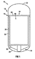
図面において、参照番号10は、本発明による支持装置を組み込んだ原子炉全体を示す。原子炉10は、原子炉圧力容器12と、該原子炉圧力容器12内に含まれる、全体が参照番号14で示される炉心バレルとを含む。原子炉10は更に、炉心バレルから原子炉圧力容器に垂直荷重を伝達する、全体が参照番号16で示された単一の垂直支持体と、炉心バレル14に対する横方向支持を提供する、全体が参照番号18(図7)で示された横方向支持手段とを含む。
In the drawings,
原子炉圧力容器12は、円筒形側壁20と、それぞれドーム形上端部及び下端部22、24を備える。
The
炉心バレル14は、円筒形側壁26と、頂部28と、底部30とを含む。炉心バレル14内には、核燃料が受けられる炉心又はチャンバ40の範囲を定める複数の反射体(図示せず)が置かれている。
The
反射体の動作上の詳細及び関連する構造的特長は、本発明の理解に不可欠ではないので、詳細には図示又は説明しない。 The operational details of the reflector and related structural features are not essential to an understanding of the present invention and are not shown or described in detail.
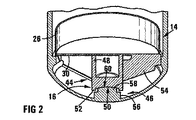
ここで図面のうち特に図2、図3、及び図5を参照すると、垂直支持体16は、上部支持部材44と下部支持部材46とを含む。
Referring now specifically to FIGS. 2, 3 and 5 of the drawings, the
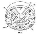
上部支持部材44は、炉心バレル14の底部30に連結され、且つ該炉心バレル14と同軸に下方に延びる円筒形中央部材48を含む。中央部材48は、下方に面する凹状接触面50を備える。中央部材48の接触面50は、環状肩部52によって囲まれた凹部として形成されている。上部支持部材44は更に、炉心バレル14の底部30に連結され、且つ中央部材48に連結されて半径方向外方に伸びる複数の角度方向に間隔を置いて配置された支持ビーム54を含む。従って、支持ビーム54は、底部30及び中央部材48に対する支持を与え、炉心バレル14の重量を中央部材48に伝達する役目をする。
The
図面のうち図2及び図5で最も良く分かるように、下部支持部材46は、原子炉圧力容器12の下端部24に固定されるベース56と、該ベースから上方に突出して凸状接触面60を備える中央配置の円筒部58とを含む。支持部材46は、原子炉圧力容器にボルト固定される。垂直支持体16を介して伝達されるのは炉心バレル組立体の重量であり、従って、負荷は垂直下側方向であることを考慮すると、これらのボルトの負荷は余り大きいものではない。突出部58の直径は、間隙を有して受け入れ可能であるように、環状肩部52の内径よりも小さい。更に、中央部材の接触面50は、円筒部58の接触面60よりも大きな曲率半径を有する。本発明の1つの実施形態においては、接触面50は、5250mmの半径を有し、接触面60は、4400mmの半径を有する。しかし当然のことながら、これらの半径は、原子炉の寸法に応じて変わる可能性があり、特定の用途に対する最適値は、定期的な試験又は経験的手段によって決定付けることができる。湾曲面は、相対移動が転動によって生じ、摺動によって生じないことを保証するために設けられる。更に、相対的に大きな半径は、所望の接触面積を得るために用いられる。
As best seen in FIGS. 2 and 5 of the drawings, the
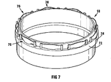
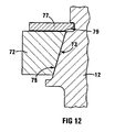
図面のうち図7、図8及び図12で最も良く分かるように、上部リング72は、原子炉圧力容器12内で所定位置に固定される。この点に関し、1つ又はそれ以上のトーションキー(torsion key)を使用して、リング72を所定位置に固定することができる。図面のうち図12で最も明確に分かるように、リング72及び圧力容器12は、相補的な下側半径方向内方にテーパが付いた面73、75を備えている。更に、環状ロッキングプレート77は、溶接又はボルトによって支持リング72に固定され、該ロッキングプレート77の半径方向外方の縁部は、原子炉容器12の環状凹部79で受けられる。この構成は、原子炉容器12の表面に対して、溶接をする必要がなくリング72を所定位置に固定する役目を果たす。
As best seen in FIGS. 7, 8 and 12 of the drawings, the
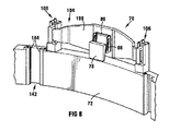
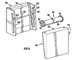
横方向支持手段18は、作動上方端部又はその方向に向けて炉心バレル14を支持するように位置付けられ複数の円周方向に間隔を置いて配置された上部横方向支持体76を含む。更に、図面のうちの図9を参照すると、各上部横方向支持体76は、内側上部支持部材78及び外側上部支持部材80を含む。以下で、より詳細に説明するように、内側上部支持部材78は炉心バレル14に固定され、外側上部支持部材80は、上部リング72に連結される。上部横方向支持部材78、80は、該支持部材78、80間に位置付けられたローラ86と接触して支持する相補的に傾斜した支持体又は軸受面82、84を定める。ローラ86は、中央配置の環状凹部90を有する円筒体88を含む。更に、ギア車92は円筒体の各端部に設けられ、円筒形軸方向突出部94はギア車92の各々から突出する。内側及び外側の上部支持部材78、80の各々には、表面82、84から突出し凹部90に受けられる中央配置のリブ96を備えている。更に、表面82、84の各々の各側部には、ギア92のそれぞれに相補的なギア98のセットが設けられる。この構成は、内側横方向支持部材78と外側横方向支持部材80との相対変位がローラ86の転動の結果として確実に行われるような役目を果たす。更に、各外側横方向支持部材80は、スロット102が設けられたチークプレート100のペアを有する。スロット102は、表面84と平行である。突出部94は、スロット102内でほとんど間隙なく受けられ、外側上部横方向支持部材80に対するローラ86の動きの範囲を制限するよう機能する。
The lateral support means 18 includes a plurality of circumferentially spaced upper lateral supports 76 positioned to support the
各外側上部横方向支持部材80は、全体が参照番号104(図8)で示される弾性変形可能な支持体上に取り付けられる。各支持体104は、上部リング72上に取り付けられるガイドポスト106のペアと、支持ポスト106間に延びる弾性変形可能なガイドビーム108とを含む。
Each outer upper lateral support member 80 is mounted on an elastically deformable support, generally indicated by reference numeral 104 (FIG. 8). Each
図面のうち図10で最も良く分かるように、各支持ポスト106は、溶接によって上部リング72に固定されるベース110と、スライダ112とを含む。ベース110及びスライダ112は、ベース110上でのスライダ112の垂直方向の相対変位を可能にする相補的リップ113及びチャンネル構成体115を有する。ベース110及びスライダ112のそれぞれの上には、調整ねじ118の一部が位置付けられる穴を協働して形成する相補的半円凹部114、116が設けられる。凹部116はねじ山が設けられる。支持ベース上に取り付けられ、ねじ122によって所定位置に保持されるカバープレート120により、調整ねじ118の垂直方向の変位が抑制される。カバープレート120は、調整ねじ118上のカラーと協動して、調整ねじ118の垂直方向の変位を抑制する。また、カバープレート120は、スライダ112をベース110上に係留して保持し、調整ねじ118の回転によるベース110に対するスライダ112の垂直方向の変位の程度を制限可能とするよう機能する。スライダ112は、ガイドビーム108の端部が受け入れ可能であるスロット126を定める。これに伴い、ガイドビームは、ガイドポスト106のペア上に支持され、板ばね様に、すなわちガイドビーム108の弾性変位をある程度可能にするように構成され、従って、外側上部横方向支持部材80がその上に取り付けられる。更に、調整ねじ118を調整することによって、ガイドビーム、従って、内側上部横方向支持部材78に対する外側上部横方向支持部材80の位置を調整して所望の予荷重を得ることができる。図示の実施形態においては、ガイドビーム108は、炉心バレルと原子炉圧力容器との間に定められた空間内に嵌合するように湾曲している。
As best seen in FIG. 10 of the drawings, each
以下に更に詳細に説明するように、垂直支持体16及び横方向支持手段18は、通常の運転状態の下で原子炉容器12内で炉心バレル14を支持する役目をする。しかしながら、例えば地震事象の結果として原子炉10が例外的な荷重を受ける可能性がある。これに応じて原子炉10は、補助支持手段を含む。補助支持手段は、全体が参照番号130(図3及び図4)で示された下部補助支持体と、全体が参照番号132(図11)で示された上部補助支持体とを含む。
As will be described in more detail below, the
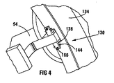
下部補助支持体130は、炉心バレル14の下端部に隣接する原子炉容器12に固定された下部支持リング134を含む。下部支持リング134は、上述のように、上部支持リング72と類似した方法で原子炉容器12内の所定位置に固定することができる。複数の半径方向内方の開放スロット138が、下部支持リング134上の円周方向に間隔を置いて配置された位置に設けられる。支持ビーム54の半径方向外方の端部がスロット内に受けられる。
The lower
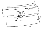
上部補助支持体132は、炉心バレル14の内壁26に連結され、そこから外方に突出する複数の円周方向に間隔を置いて配置されたリブ140を含む。相補的に半径方向内方に向けられたスロット142が、リブ140のスロット部を受けることが可能な上部支持リング72上で円周方向に間隔を置いて配置された位置に設けられる。
The upper
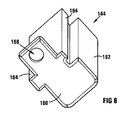
通常の使用では、例えば、温度変化、膨張率の差、及び同様のものの結果として、炉心バレル14と原子炉圧力容器12間の幾らかの相対移動が存在することは理解されるところである。支持ビーム54と下部支持リング134間、及びリブ140と上部支持リング72間の間隙は、この相対移動を可能にするように選択されることになる。スロット138、142の所望の間隙を得るためにシム144が利用され、その1つが図面のうちの図6に示されている。シムは、所望の寸法に加工されて、下部支持リング134及び上部支持リング72上に取り付けられ、支持ビーム54とリブ140の端部間にそれぞれ所望の間隙が得られるようにする。図面のうち図6で最も良く分かるように、各シム144は、端プレート160と、該端プレート160から突出する本体部分162とを含む。対向して配置された平行リブ164は、本体162から横方向外方に突出し、支持リング72、134の相補的な垂直方向に延びる対向して内方に配置されたチャンネル構成体内に摺動自在に受けることが可能である。シムは、端プレート160の突出部の相補的な穴168を貫通して延びるねじ166によってこの位置に保持される。
It will be appreciated that in normal use, there will be some relative movement between the
炉心バレルは通常、約22メートルの長さ及び約18メートルの円周を有する。炉心バレルは運転中に加熱され、運転停止中に冷却される。材料温度制約条件内に留まるように、炉心バレルは外側を冷却する必要があり、このために炉心バレル冷却システムが設けられる。しかしながら、炉心バレル側面は、どのような所与の高さにおいても円周全体で均一な温度になる可能性は少ない。温度変動は、炉心バレル円周回りの炉心バレル冷却システムガスの一様ではない流れ、例えば製造公差に起因する側面反射体と炉心バレル側部との間の一様でないギャップ、原子炉圧力容器と炉心バレルとの間のこれらの構成部品の両方の製造公差に起因する一様でないギャップ、入口及び出口パイプの構成部品の非対称形配置、又は同様のものなどの種々の要因から生じる可能性がある。炉心バレル上の温度分布が一様でないことにより、炉心バレルの何らかの横方向の変形、例えば僅かな曲がりが発生する可能性がある。中央に配置された単一の垂直支持体16上で炉心バレルの重量を支持することによって、炉心バレルは、例外的な応力が炉心バレル又は支持構造体内に誘起されることなく曲がることができる。これによって、炉心バレルは一様でない温度分布の影響を受けなくなる。従来技術の欠点は、炉心バレルが複数の離間した垂直支持体に支持されることである。炉心バレルが移動する結果として、支持体すなわち炉心バレルの一様でない荷重が生じる可能性があり、望ましくない高いレベルの応力をもたらす可能性がある。この問題は、単一の中央に配置された垂直支持体16を利用することによって回避される。
The core barrel typically has a length of about 22 meters and a circumference of about 18 meters. The core barrel is heated during operation and cooled during shutdown. In order to remain within the material temperature constraints, the core barrel must be cooled on the outside, and for this purpose a core barrel cooling system is provided. However, the core barrel side is less likely to be at a uniform temperature throughout the circumference at any given height. Temperature fluctuations can result in uneven flow of core barrel cooling system gas around the core barrel circumference, such as uneven gaps between side reflectors and core barrel sides due to manufacturing tolerances, reactor pressure vessels, It can result from various factors such as non-uniform gaps due to manufacturing tolerances of both of these components to the core barrel, asymmetrical arrangement of inlet and outlet pipe components, or the like . The non-uniform temperature distribution on the core barrel can cause some lateral deformation of the core barrel, for example a slight bend. By supporting the weight of the core barrel on a single centrally disposed
更に、当然ながら、温度並びに使用する材料の差異の結果として、炉心バレルと原子炉圧力容器の膨張の速度及び程度が異なる可能性がある。この点において、上部横方向支持体76は、炉心バレルの上端部を支持する役目を果たす。炉心バレルが加熱されると、垂直方向及び半径方向の両方で膨張する。これにより、内側上部横方向支持部材78が、外側上部横方向支持部材80に対して上方及び半径方向外方に変位するようになる。しかしながら、支持面82、84の傾斜はこの膨張を可能にし、支持面をローラ86の表面に接触した状態に保持する。また、ガイドビーム108の固有の弾性は、ある程度の横方向移動を許容する。何らかの理由で表面82、84がローラ86と接触しなくなった場合、ローラは、ギア92、98によって所定位置に保持されることになる。表面82、84間の分離が更に大きくなりギア92、94が接触しなくなった場合には、ローラは、突出部94がスロット102の底部に位置付けられるまで表面84を転動して降下する。これによって、ローラ86が原子炉圧力容器12と炉心バレル14間に確実に落下しなくなる。表面82、84は通常、垂直方向に対し約10°の角度で傾斜している。しかしながら、この角度は、特定の用途における定期的な試験又は経験によって決定される最適性に応じて変わる場合がある点は認識されるであろう。
Furthermore, of course, the speed and extent of expansion of the core barrel and the reactor pressure vessel may differ as a result of temperature and material differences used. In this respect, the upper
例えば地震事象の結果として異常な荷重が原子炉10に付加された場合、単一の垂直支持体16が炉心バレル14の重量を支持することになるが、ガイドビーム108が変形するので、上部横方向支持体76は水平方向の支持を炉心バレル14に対し十分に与えることができない可能性がある。偏差が十分である場合、支持ビーム54端部とスロット138間、及びリブ140とスロット142間のギャップは近接し、これにより水平荷重が炉心バレル14から原子炉圧力容器12に伝達される。地震事象の後、ガイドビーム108によって炉心バレル14は中央に配置され、リブ140とスロット142間のギャップが広がる。この点において、ガイドビーム108は、この変形に対処して製造材料の弾性領域内に留まるように設計されることは理解されるであろう。
For example, if an abnormal load is applied to the
当然ながら、支持装置の幾つかの変形が実施可能である。例えば、下部支持部材46は、炉心バレルによって伝達される荷重を原子炉圧力容器のより大きな面積にわたって広げるよう設計されたビーム構成によって原子炉圧力容器に連結することができる。
Of course, several variations of the support device are possible. For example, the
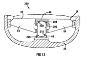
支持装置の別の変形形態を、図面のうちの図13に示しており、参照番号200は、本発明による支持装置を組み込んだ別の原子炉の一部を全体的に示すものであり、特に指示がない限り、上記で使用したのと同じ参照番号は同じ部品を示すのに使用される。
Another variant of the support device is shown in FIG. 13 of the drawings, the
原子炉200の支持装置と原子炉10の支持装置との間の主な相違点は、原子炉200の場合の、支持装置が上部支持部材44と下部支持部材46との間に配置された中間部材202を含むことである。中間部材202は、凸状の上部接触面と下部接触面204、206を有する略長円の形状である。上部支持部材44及び下部支持部材46は凹状支持面208、210を有する。支持面208、210の半径は支持面204、206の半径よりも大きい。
The main difference between the support device of the
この構成の利点は、自己調心式であることである。 The advantage of this configuration is that it is self-aligning.
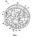
次に、図面のうちの図14から図16を参照すると、本発明による支持装置を組み込んだ別の原子炉の一部が参照番号300で全体的に示されており、特に指示がない限り、上記で使用した同じ参照番号は、同じ要素を示すのに使用されている。
Referring now to FIGS. 14-16 of the drawings, a portion of another nuclear reactor incorporating a support apparatus according to the present invention is generally indicated by
本発明のこの実施形態においては、環状スカート302が炉心バレルの底部30から下方に垂下する。支持ビーム54は、炉心バレル14の底部30と中央部材48とに連結されて半径方向外方に延びており、支持ビーム54の半径方向外方の端部がスカート302に連結される。
In this embodiment of the invention, an
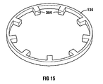
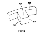
更に、図15に示す実施形態においては、突出部304は、下部支持リング134から半径方向内方に突出する。突出部304は、スカート302内に設けられたスロット306を貫通して延びる。従って、スカート302及び突出部304は、地震事象時に生じる可能性のあるような例外的荷重を受けた際に、炉心バレルを支持する下部補助支持体130として機能する。突出部304とスロット306との間に所望の間隙を得るために、シム308を使用することができる。更に、図面のうち図16で最も良く分かるように、各突出部304は凸状側部310を有し、これは地震事象の際にシム308と接触する。凸状側部310によって、例えば、炉心バレルの曲がりの結果として、スカート302が水平に対し若干の角度をなした場合でも確実に小さな接触応力が発生する。
Further, in the embodiment shown in FIG. 15, the
更に、本発明のこの実施形態においては、横方向支持手段は、3つの弾性変形可能な位置決め要素又はビーム312備えた下部横方向支持体を含む。ビーム312の内端部は、上部支持部材48上に設けられた凹部314の形で内側受け入れ構成体に配置され、ビーム312の半径方向外方端部は、突出部304のうち3つに取り付けられるシム318上に設けられた相補的凹部316内に位置付けられる。シム318は、ビーム312において所望の予荷重を得るのに使用される。ビーム312は、最大の偏差を得て地震事象時にビーム内応力が最小となるように湾曲しており、突出部304とシム308間の間隔が近接することができるようビーム312が十分に変形し、これにより横荷重が炉心バレルから原子炉圧力容器に伝達されるようになる。地震事象後、ビーム312は中央部材48を中央に配置し、突出部304とシム308との間のギャップを回復する。
Furthermore, in this embodiment of the invention, the lateral support means comprises a lower lateral support with three elastically deformable positioning elements or beams 312. The inner end of the
発明者らは、従来技術によるシステムと比較すると、本発明により温度変動を受ける容器並びに支持構造体に加わる応力が小さくなると考えている。更に、原子炉の特定の場合においては、本発明は、応力を増大させることなく炉心バレルの曲がり量を小さくすることを可能にする。炉心バレルは、一様ではない温度分布を許容することができる。更に、炉心バレルは、原子炉圧力容器に対して半径方向並びに軸方向に膨張することができる。支持体104の調整を可能にすることによって、上端部に隣接する炉心バレルの横方向支持体を調節して、炉心バレルの自己調芯及び安定化を確実にすることができる。更に、上部及び下部支持リング上に設けられたシムは、取り付け中にサイズが決められ、これにより確実に所望の間隔取り又は許容公差が実現される。
The inventors believe that the stress applied to the container and support structure subjected to temperature fluctuations by the present invention is reduced compared to systems according to the prior art. Furthermore, in the specific case of a nuclear reactor, the present invention allows the core barrel bend to be reduced without increasing the stress. The core barrel can tolerate a non-uniform temperature distribution. Furthermore, the core barrel can expand radially as well as axially relative to the reactor pressure vessel. By allowing the
10 原子炉
12 原子炉圧力容器
14 炉心バレル
16 垂直支持体
18 横方向支持手段
20 円筒形側壁
22 ドーム形上端部
24 ドーム形下端部
26 円筒形側壁
28 頂部
30 底部
40 チャンバ
DESCRIPTION OF
Claims (29)
前記容器の重量を支持する単一の垂直支持体と、
少なくとも前記単一の垂直支持体を上回る高さにあり、前記容器に対する横方向支持を与える横方向支持手段と、
を含む支持装置。 A container to be supported;
A single vertical support for supporting the weight of the container;
Lateral support means at least above the single vertical support and providing lateral support for the container;
Supporting device including.
内容物を伴う前記容器の重量を単一の垂直支持体を介して支持装置に伝達する段階と、
少なくとも前記垂直支持体を上回る高さにある位置で前記容器を横方向に支持する段階とを含む方法。 A method of supporting a container,
Transmitting the weight of the container with contents to a support device via a single vertical support;
Supporting the container laterally at a position at least above the vertical support.
前記炉心バレル及びその内容物の重量を単一の垂直支持体を介して前記原子炉圧力容器に伝達する段階と、
前記垂直支持体を上回る高さに位置付けられた横方向支持体を介して前記炉心バレルと前記原子炉圧力容器との間で横荷重を伝達する段階と、
を含む請求項28に記載の方法。 When the vessel is in the form of a high temperature gas cooled reactor core barrel including a reactor pressure vessel in which the core barrel is supported, the method comprises:
Transferring the weight of the core barrel and its contents to the reactor pressure vessel via a single vertical support;
Transmitting a lateral load between the core barrel and the reactor pressure vessel via a lateral support positioned at a height above the vertical support;
30. The method of claim 28, comprising:
Applications Claiming Priority (2)
| Application Number | Priority Date | Filing Date | Title |
|---|---|---|---|
| ZA200306376 | 2003-08-15 | ||
| PCT/IB2004/001738 WO2005017920A2 (en) | 2003-08-15 | 2004-05-27 | A support arrangement |
Publications (3)
| Publication Number | Publication Date |
|---|---|
| JP2007502425A true JP2007502425A (en) | 2007-02-08 |
| JP2007502425A5 JP2007502425A5 (en) | 2007-07-12 |
| JP4531046B2 JP4531046B2 (en) | 2010-08-25 |
Family
ID=34195113
Family Applications (1)
| Application Number | Title | Priority Date | Filing Date |
|---|---|---|---|
| JP2006523692A Expired - Lifetime JP4531046B2 (en) | 2003-08-15 | 2004-05-27 | Support device |
Country Status (10)
| Country | Link |
|---|---|
| US (1) | US8077824B2 (en) |
| EP (1) | EP1665288B1 (en) |
| JP (1) | JP4531046B2 (en) |
| KR (1) | KR101058202B1 (en) |
| CN (1) | CN1836292B (en) |
| AT (1) | ATE382184T1 (en) |
| CA (1) | CA2535280C (en) |
| DE (1) | DE602004010919T2 (en) |
| WO (1) | WO2005017920A2 (en) |
| ZA (1) | ZA200601194B (en) |
Cited By (1)
| Publication number | Priority date | Publication date | Assignee | Title |
|---|---|---|---|---|
| JP2023538028A (en) * | 2020-08-17 | 2023-09-06 | テラパワー, エルエルシー | Cartridge Core Barrel for Nuclear Reactor |
Families Citing this family (21)
| Publication number | Priority date | Publication date | Assignee | Title |
|---|---|---|---|---|
| JP5410950B2 (en) * | 2009-01-15 | 2014-02-05 | 株式会社日立ハイテクノロジーズ | Plasma processing equipment |
| CN102347087A (en) * | 2011-09-01 | 2012-02-08 | 李志胜 | Anti-vibration device for nuclear power plant reactor |
| US9850430B2 (en) * | 2013-03-12 | 2017-12-26 | Amec Foster Wheeler Usa Corporation | Method and system for utilizing selectively de-coupleable connections for modular installation of a coke drum |
| JP2015105867A (en) * | 2013-11-29 | 2015-06-08 | 株式会社東芝 | Shroud support device and shroud support device remodeling method |
| WO2015102742A1 (en) * | 2013-12-31 | 2015-07-09 | Nuscale Power, Llc | Seismic attenuation system for a nuclear reactor |
| KR101651412B1 (en) * | 2014-11-20 | 2016-08-26 | 두산중공업 주식회사 | Reactor core support barrel aligment device and aligment method for an internal sturcture |
| EP3393645A1 (en) * | 2015-12-22 | 2018-10-31 | Shell Internationale Research Maatschappij B.V. | Tray support inserts for chemical reactor vessels and methods of use catalyst |
| CN105913889A (en) * | 2016-07-05 | 2016-08-31 | 上海核工程研究设计院 | Three-loop nuclear energy system |
| CN106448751B (en) * | 2016-07-12 | 2018-02-13 | 华能山东石岛湾核电有限公司 | A kind of HTGR metal in-pile component reactor core shell supporting structure and installation method |
| CN108953855B (en) * | 2018-08-01 | 2024-06-18 | 中广核研究院有限公司 | Layered support device for reactor |
| CN108980532B (en) * | 2018-08-01 | 2024-05-10 | 中广核研究院有限公司 | Reactor support foundation arrangement |
| CN109830314B (en) * | 2019-01-29 | 2023-09-08 | 中广核工程有限公司 | Reactor pressure vessel limiting structure |
| US11289216B2 (en) * | 2019-05-16 | 2022-03-29 | Framatome Inc. | Nuclear reactor core shroud securing device |
| KR102223774B1 (en) * | 2019-11-04 | 2021-03-05 | 한국전력기술 주식회사 | Apparatus for supporting pressurizer in nuclear power plant |
| RU2726737C1 (en) * | 2019-12-03 | 2020-07-15 | Акционерное Общество "Российский Концерн По Производству Электрической И Тепловой Энергии На Атомных Станциях" (Ао "Концерн Росэнергоатом") | External heat insulation of nuclear reactor housing and system for installation of external heat insulation of housing of nuclear reactor |
| CN112879561B (en) * | 2021-01-12 | 2023-03-10 | 桂林理工大学 | Support structure for vertical pressure vessel |
| US11742098B2 (en) | 2021-01-25 | 2023-08-29 | Westinghouse Electric Company Llc | Nuclear reactor core support system providing radial and axial support |
| CN113782232B (en) * | 2021-08-30 | 2025-04-08 | 中国原子能科学研究院 | A high temperature gas-cooled nuclear reactor structure and nuclear power equipment |
| CN114582530B (en) * | 2022-01-25 | 2024-10-15 | 中国核工业第五建设有限公司 | Supporting and mounting method for reactor pressure vessel |
| CN114842993A (en) * | 2022-04-07 | 2022-08-02 | 山东核电有限公司 | Device for realizing temporary storage of upper reactor internals in reactor |
| CN116168862B (en) * | 2023-01-13 | 2025-09-30 | 中广核研究院有限公司 | A nuclear power guide cylinder auxiliary device |
Citations (6)
| Publication number | Priority date | Publication date | Assignee | Title |
|---|---|---|---|---|
| JPS5224693A (en) * | 1975-08-20 | 1977-02-24 | Fuji Electric Co Ltd | Support device of reaceor center block support pate at nuclear reactor |
| JPS5314290A (en) * | 1976-07-23 | 1978-02-08 | Fuji Electric Co Ltd | Core restraining mechanism for gas-cooled reactor |
| JPS5815193A (en) * | 1981-07-22 | 1983-01-28 | 株式会社東芝 | Supporting device of reactor shroud |
| JPS5847794U (en) * | 1981-09-28 | 1983-03-31 | 富士電機株式会社 | Core support mechanism of gas-cooled reactor |
| JPS6358797U (en) * | 1986-10-06 | 1988-04-19 | ||
| JPH06281776A (en) * | 1993-03-25 | 1994-10-07 | Toshiba Corp | Boiling water reactor |
Family Cites Families (10)
| Publication number | Priority date | Publication date | Assignee | Title |
|---|---|---|---|---|
| GB808739A (en) * | 1956-05-03 | 1959-02-11 | Ass Elect Ind | Improvements relating to supports for large structures |
| GB889758A (en) * | 1958-01-31 | 1962-02-21 | English Electric Co Ltd | Improvements relating to nuclear reactors |
| LU46789A1 (en) * | 1964-08-18 | 1966-02-18 | ||
| US3554868A (en) * | 1967-10-09 | 1971-01-12 | Westinghouse Electric Corp | Reactor internals lower radial support system |
| US4008757A (en) | 1975-09-22 | 1977-02-22 | The Babcock & Wilcox Company | Industrial technique |
| US3986581A (en) * | 1976-02-17 | 1976-10-19 | Minnesota Mining And Manufacturing Company | Damping unit for globular storage tank |
| JPS5673387A (en) * | 1979-11-20 | 1981-06-18 | Tokyo Shibaura Electric Co | Nuclear reactor core supporting frame device |
| AU8396782A (en) * | 1981-05-18 | 1982-12-07 | Toyama, J. | A vibration-damping device |
| DE4206661A1 (en) * | 1992-03-03 | 1993-09-09 | Siemens Ag | SAFETY DEVICE AGAINST OVERPRESSURE FAILURE OF A CORE REACTOR PRESSURE TANK |
| US5772420A (en) * | 1996-12-16 | 1998-06-30 | Holmes; Henry T. | Greaseless mold carrier and alignment system |
-
2004
- 2004-05-27 JP JP2006523692A patent/JP4531046B2/en not_active Expired - Lifetime
- 2004-05-27 DE DE602004010919T patent/DE602004010919T2/en not_active Expired - Lifetime
- 2004-05-27 WO PCT/IB2004/001738 patent/WO2005017920A2/en not_active Ceased
- 2004-05-27 CA CA2535280A patent/CA2535280C/en not_active Expired - Lifetime
- 2004-05-27 CN CN2004800230493A patent/CN1836292B/en not_active Expired - Lifetime
- 2004-05-27 EP EP04735054A patent/EP1665288B1/en not_active Expired - Lifetime
- 2004-05-27 KR KR1020067003183A patent/KR101058202B1/en not_active Expired - Lifetime
- 2004-05-27 US US10/568,460 patent/US8077824B2/en not_active Expired - Lifetime
- 2004-05-27 AT AT04735054T patent/ATE382184T1/en not_active IP Right Cessation
-
2006
- 2006-02-09 ZA ZA200601194A patent/ZA200601194B/en unknown
Patent Citations (6)
| Publication number | Priority date | Publication date | Assignee | Title |
|---|---|---|---|---|
| JPS5224693A (en) * | 1975-08-20 | 1977-02-24 | Fuji Electric Co Ltd | Support device of reaceor center block support pate at nuclear reactor |
| JPS5314290A (en) * | 1976-07-23 | 1978-02-08 | Fuji Electric Co Ltd | Core restraining mechanism for gas-cooled reactor |
| JPS5815193A (en) * | 1981-07-22 | 1983-01-28 | 株式会社東芝 | Supporting device of reactor shroud |
| JPS5847794U (en) * | 1981-09-28 | 1983-03-31 | 富士電機株式会社 | Core support mechanism of gas-cooled reactor |
| JPS6358797U (en) * | 1986-10-06 | 1988-04-19 | ||
| JPH06281776A (en) * | 1993-03-25 | 1994-10-07 | Toshiba Corp | Boiling water reactor |
Cited By (2)
| Publication number | Priority date | Publication date | Assignee | Title |
|---|---|---|---|---|
| JP2023538028A (en) * | 2020-08-17 | 2023-09-06 | テラパワー, エルエルシー | Cartridge Core Barrel for Nuclear Reactor |
| JP7661482B2 (en) | 2020-08-17 | 2025-04-14 | テラパワー, エルエルシー | Cartridge core barrel for nuclear reactor |
Also Published As
| Publication number | Publication date |
|---|---|
| KR101058202B1 (en) | 2011-08-22 |
| US20070076836A1 (en) | 2007-04-05 |
| WO2005017920A2 (en) | 2005-02-24 |
| DE602004010919T2 (en) | 2008-12-11 |
| KR20060109424A (en) | 2006-10-20 |
| ATE382184T1 (en) | 2008-01-15 |
| DE602004010919D1 (en) | 2008-02-07 |
| EP1665288B1 (en) | 2007-12-26 |
| WO2005017920A3 (en) | 2005-05-06 |
| CA2535280A1 (en) | 2005-02-24 |
| JP4531046B2 (en) | 2010-08-25 |
| CN1836292B (en) | 2011-07-06 |
| US8077824B2 (en) | 2011-12-13 |
| CA2535280C (en) | 2013-02-19 |
| CN1836292A (en) | 2006-09-20 |
| EP1665288A2 (en) | 2006-06-07 |
| ZA200601194B (en) | 2007-05-30 |
Similar Documents
| Publication | Publication Date | Title |
|---|---|---|
| JP4531046B2 (en) | Support device | |
| CN105605096B (en) | Angular contact self-aligning toroidal rolling element bearing | |
| CN103649342B (en) | Tilting-type oxygen coverter | |
| EP2852692B1 (en) | Suspension device for tilting oxygen converters and converter provided with said suspension device | |
| US8616778B2 (en) | Rolling bearing apparatus | |
| JP2007502425A5 (en) | ||
| US4442066A (en) | Supporting floor for the core of a nuclear reactor | |
| EP2526359B1 (en) | Metallurgical furnace | |
| US4474729A (en) | Support structure for a prestressed cylindrical pressure vessel | |
| ZA200702008B (en) | Nuclear reactor | |
| CN107532670A (en) | Spring carrier | |
| JPS58193973A (en) | pressure vessel | |
| US4752436A (en) | Nuclear component horizontal seismic restraint | |
| US5738822A (en) | Shaft furnace charging device with rotating chute | |
| EP2284842B1 (en) | Pressure vessel sliding support unit and system using the sliding support unit | |
| EP3910190B1 (en) | Mounting assembly for a rocket engine and rocket | |
| CN105143472B (en) | Fixing systems for tiltable metallurgical processing vessels | |
| JPH0210194A (en) | Upper interior equipment for water cooled deceleration reactor | |
| US4517927A (en) | Steam generator for liquid metal fast breeder reactor | |
| US4671923A (en) | Holddown spring retention assembly | |
| CN101429970B (en) | Offset thrust bearing | |
| EP3431791B1 (en) | Bearing arrangement for a tiltable converter | |
| JPH1182495A (en) | Cylindrical roller bearing equipped with aligning ring | |
| SU152692A1 (en) |
Legal Events
| Date | Code | Title | Description |
|---|---|---|---|
| A521 | Request for written amendment filed |
Free format text: JAPANESE INTERMEDIATE CODE: A523 Effective date: 20070526 |
|
| A621 | Written request for application examination |
Free format text: JAPANESE INTERMEDIATE CODE: A621 Effective date: 20070526 |
|
| A131 | Notification of reasons for refusal |
Free format text: JAPANESE INTERMEDIATE CODE: A131 Effective date: 20091027 |
|
| A521 | Request for written amendment filed |
Free format text: JAPANESE INTERMEDIATE CODE: A523 Effective date: 20091102 |
|
| TRDD | Decision of grant or rejection written | ||
| A01 | Written decision to grant a patent or to grant a registration (utility model) |
Free format text: JAPANESE INTERMEDIATE CODE: A01 Effective date: 20100511 |
|
| A01 | Written decision to grant a patent or to grant a registration (utility model) |
Free format text: JAPANESE INTERMEDIATE CODE: A01 |
|
| A61 | First payment of annual fees (during grant procedure) |
Free format text: JAPANESE INTERMEDIATE CODE: A61 Effective date: 20100608 |
|
| R150 | Certificate of patent or registration of utility model |
Ref document number: 4531046 Country of ref document: JP Free format text: JAPANESE INTERMEDIATE CODE: R150 Free format text: JAPANESE INTERMEDIATE CODE: R150 |
|
| FPAY | Renewal fee payment (event date is renewal date of database) |
Free format text: PAYMENT UNTIL: 20130618 Year of fee payment: 3 |
|
| R250 | Receipt of annual fees |
Free format text: JAPANESE INTERMEDIATE CODE: R250 |
|
| R250 | Receipt of annual fees |
Free format text: JAPANESE INTERMEDIATE CODE: R250 |
|
| R250 | Receipt of annual fees |
Free format text: JAPANESE INTERMEDIATE CODE: R250 |
|
| R250 | Receipt of annual fees |
Free format text: JAPANESE INTERMEDIATE CODE: R250 |
|
| R250 | Receipt of annual fees |
Free format text: JAPANESE INTERMEDIATE CODE: R250 |
|
| R250 | Receipt of annual fees |
Free format text: JAPANESE INTERMEDIATE CODE: R250 |
|
| R250 | Receipt of annual fees |
Free format text: JAPANESE INTERMEDIATE CODE: R250 |
|
| R250 | Receipt of annual fees |
Free format text: JAPANESE INTERMEDIATE CODE: R250 |
|
| R250 | Receipt of annual fees |
Free format text: JAPANESE INTERMEDIATE CODE: R250 |
|
| R250 | Receipt of annual fees |
Free format text: JAPANESE INTERMEDIATE CODE: R250 |
|
| R250 | Receipt of annual fees |
Free format text: JAPANESE INTERMEDIATE CODE: R250 |
|
| EXPY | Cancellation because of completion of term |